Table of Contents
Advertisement
Quick Links
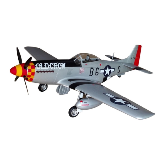
P-51D Mustang 89"
Speci cation:
Wing Span: 2260mm/89in
Length: 1965mm/77.4in
Flying Weight: ~11.2kg
Wing area: 90.2dm2
Engine: 50-60cc, rear exhaust
R/C System: 8+ channel radio system
Servo: 10
C.G: 170mm back from the leading edge at wing root
TopRCModel-USA.com
SAFETY PRECAUTIONS
INSTRUCTION MANUAL
This R/C airplane is not a toy!
(The people under 18 years old is forbidden from flying this model)
First-time builders should seek advice from people having building
experience.If misused or abused,it can cause serious bodily injury
and damage to property.
Fly only in open areas and preferably at a dedicated R/C flying site.
We suggest having a qualified instructor carefully inspect your
airplane before its first flight.Please carefully read and follow all
instructions included with this airplane,your radio control system
and any other components purchased separately.
Advertisement
Table of Contents

Related Manuals for Top RC Model P-51D Mustang 89


Summary of Contents for Top RC Model P-51D Mustang 89
- Page 1 P-51D Mustang 89" Speci cation: Wing Span: 2260mm/89in Length: 1965mm/77.4in Flying Weight: ~11.2kg Wing area: 90.2dm2 Engine: 50-60cc, rear exhaust R/C System: 8+ channel radio system Servo: 10 C.G: 170mm back from the leading edge at wing root INSTRUCTION MANUAL TopRCModel-USA.com...
- Page 2 Gasoline tube Gasoline 6 channel radio for aiplane is highly recommended for this model. 35cc gas engine 5.75 in scale spinner Optional electric retract set Motor 100mm 92.5mm 51mm Motor: 12S 5000MAH 180KV 89mm High Voltage ESC 130A We strongly recommen you use the thread lock for all the screws when you build your model.
- Page 3 Assemble the aileron to main wing with instant type AB glue. Be careful Accessory list for the coming installation steps. to ensure the moving parts of the hinges are able to move freely. Horn Pivot & round hinge(5x68mm) Pivot & round hinge(5x68mm) Clevis(2mm) Push rod(2mm) Screw (2x10mm)
- Page 4 Assemble the servo of the aileron to the wing with screws. Epoxy the pin hinges to the slots in the flap. Pivot & round hinge(5x68mm) TP Screw (3x16mm) TP Screw (3x12mm) Make sure hinges are mounted in the same line. Assemble the servo tray to the wing with screws Keep some space about 1mm width between and epoxy the fiber horn to the aileron.
- Page 5 Install the L brackets to the servo of flap as Assemble the servo tray to the wing with screws and illustration below. epoxy the fiber horn to the flap. TP Screw (2.3x12mm) Screw (3x5mm) L bracket Washer (3x6mm) 1.5mm Masking tape L bracket Screw (3x5mm) Washer(3x5mm)
- Page 6 Assemble the landing gear to the appropriate position in The sketch map of the wing fits well to the fuselage. the landing gear mount. TP Screw (3x20mm) Washer(3x6mm) TP Screw (3x20mm) Washer(3x6mm) Factory already set blind nuts in the wings, the customers can Drag the servo line and retracts lines from the wing.
- Page 7 Epoxy the elevator to the stabilizer. Accessory list for the coming installation steps. Horn TP Screw (2.3x12mm) Rod (2x200mm) pivot & round hinge(5x68mm) Copper joiner carbon ber tube(14x423mm)A Steel wire (0.5x3000mm) carbon ber tube(14x213mm)B Aluminum tube Washer(3x8mm) Horn Screw (2.6x12mm) Pin hinge(36x20x1mm) Screw (2x10mm) Clevis...
- Page 8 Assemble the stab to the fuselage drill a hole to The sketch map after the servo and linkage connect. the other section stab. Screw (2.6x12mm) Washer(3x8mm) 1.5mm Washer(3x8mm) Screw (2.6x12mm) Glue the wooden block to each side of the stab tube as below, put the stab Epoxy the pivot &...
- Page 9 The sketch map should be when the stabilizer The pictures of the tail gear when it up and down. assembly completion. Make sure to glue securely. If not properly glued, a failure in flight may occur. Securely glue together.If coming off during flights, you'll lose control of your airplane which leads to accidents! Temporarily fasten down the main wing and...
- Page 10 Connect the steel wires of the rudder horn and Assemble the servo of the tail landing gear to the tail gear to the servo. fuselage. Epoxy the pinned hinges and drill holes through the The sketch map of how the wires working in the tail gear door.
- Page 11 Epoxy the pinned hinges,horns to the appointed position Assemble the servos of gear doors to the fuselage. on the outer gear doors and drill holes to appropriate position in the outer gear door as illustration. Screw (2x10mm) Washer(2x5mm) TP Screw (2x10mm) Horn Lock Nut (2mm ) 1.0mm...
- Page 12 Epoxy the pinned hinges,horns to the inner gear door carefully, Epoxy the wooden blocks carefully to the fuselage for drill holes through the gear door and pinned hinges and fix the installing the gear door servos. pinned hinges tightly to the inner gear door. Wooden Block(22x20x9mm) Assemble the inner gear door to the fuselage with screws Assemble the servos of gear doors to the fuselage.
- Page 13 Connect the innner gear doors and the servos througn Accessory list for the coming installation steps. the slot in the fuselage. Linkage Stopper Plastic tube (2x650mm) Fuel tank (800cc) The sketch map of the servos for the gear doors The side view when the engine install completion. assembled ready.
- Page 14 Install the engine to the engine mount with screws. Accessory list for the coming installation steps. Fly frame(3mm) Wheel (115mm) Alu bolt Exhaust Fuel tank rack (A) Scale antenna Fuel tank rack (B) Air scoop Wire hook(2mm) Fuel tank carrier Screw (3x10mm) TP Screw (2.3x8mm) Washer(3x6mm)
- Page 15 Assemble the cockpit to the fuselage. Cut off the surplus part from the PVC canopy. Glue the canopy parts to the fiber frames carefully, put the ply Take the cockpit out and assemble the scale antenna with frame to appropriate position in the cockpit and cover the canopy screw as illustration.
- Page 16 Put out the metal hook, the fuel tank will drop down. Install the fuel tank rack to the fuel tank with screws Alu bolt Alu bolt Fuel tank rack (A) TP Screw (2.3x12mm) Screw (3x10mm) Fuel tank rack (B) Washer(3x6mm) Fuel tank rack (B) Fuel tank rack (A) Alu bolt...
- Page 17 Adjustment. The centre of the Gravity. Top view ELEVATOR 30mm 30mm 170mm Side View Position for Centre of Gravity. right diagram. TopRCModel-USA.com...
- Page 18 Accessories packing list TP Screw (2x10mm) Servo tray(2mm) TP Screw (2.3x8mm) Wooden Block(22x20x9mm) TP Screw (2.3x12mm) Fly frame(3mm) Screw (2.6x12mm) Exhaust Screw (3x10mm) Scale antenna Screw (2x10mm) Air scoop Locknut (2mm ) Fuel tank carrier Washer(2x5mm) Washer(3x6mm) Gear door 1 Copper joiner Aluminum tube Gear door 2...
- Page 19 TopRCModel-USA.com...
Need help?
Do you have a question about the P-51D Mustang 89 and is the answer not in the manual?
Questions and answers