Advertisement
Quick Links
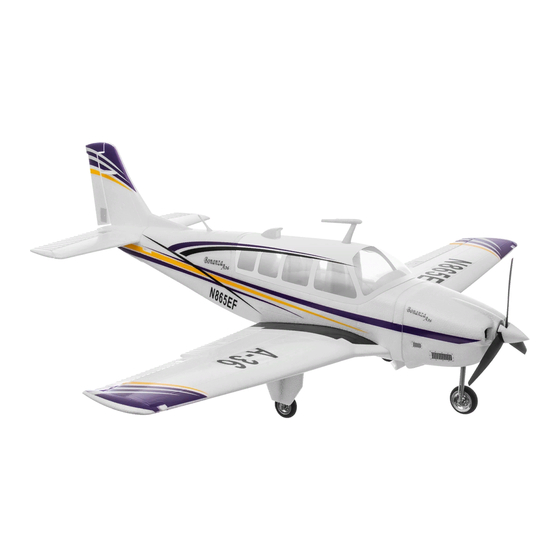
Beechcraft Bonanza V35/A36
Before commencing assembly, pleass read instruction thoroughly
V35ST/V35UP Technical data:
Specification:
Wingspan: 1280mm
Length: 1030mm
Weight: 1384g / 1442g
Configuration
Radio: 6CHanneL 2.4G radio
Motor: 3715 980KV
ESC: 30A / 50A
Battery: 11.1V 2200mA 20C lipo / 14.8V 2200mA 20C lipo
Servo: 9g * 1PCS + 17g * 3PCS / 9g * 2PCS + 17g * 3PCS
Charger: 3S lipo balancer and adapter / 4S lipo balancer
and 3A adapter
Propeller: 1070 3blades
Assembly Instructions
A36ST/A36UP Technical data:
Specification:
Wingspan: 1280mm
Length: 1030mm
Weight: 1384g / 1442g
Configuration
Radio: 6CHanneL 2.4G radio
Motor: 3715 980KV
ESC: 30A / 50A
Battery: 11.1V 2200mA 20C lipo / 14.8V 2200mA 20C lipo
Servo: 9g * 1PCS + 17g * 3PCS / 9g * 2PCS + 17g * 3PCS
Charger: 3S lipo balancer and adapter / 4S lipo balancer
and 3A adapter
Propeller: 1070 3blades
Advertisement

Related Manuals for Top RC Model Beechcraft Bonanza V35


Summary of Contents for Top RC Model Beechcraft Bonanza V35
-
Page 1: Assembly Instructions
Assembly Instructions Beechcraft Bonanza V35/A36 Before commencing assembly, pleass read instruction thoroughly A36ST/A36UP Technical data: Specification: Wingspan: 1280mm Length: 1030mm Weight: 1384g / 1442g Configuration Radio: 6CHanneL 2.4G radio Motor: 3715 980KV ESC: 30A / 50A Battery: 11.1V 2200mA 20C lipo / 14.8V 2200mA 20C lipo... -
Page 2: Battery And Charging
1. This RC model is not a toy. The owner / pilot is responsible for any damage to persons or propety that results from the use of this producer 2. It is very important to follow All instructions for setting up and debugging the model before attempting to flight 3. - Page 3 4. Do not fly or launch the model towards people’s faces. 5. Do not fly in strong winds or rain or thunderstorms. 6. Keep your hands and face away from the propeller.
- Page 4 Pictures of Battery Charging The Use of Tools...
- Page 5 Component Fuselage, Main wing, Elevator, Rudder, Transmitter, Adapter, Balancer, Manual, Propeller, Propeller spinner, Battery, Control rod, Accessories package, Canopy and decoration Assembly Instructions 3x15mm Rod adjuster...
- Page 6 Main wing servos assembly Assembly the aileron servo and flaps servo to the indication position by glue as picture Servo protector assembly Apply glue to the protector then fix it to the appointed place as picture Clevis assembly Turn the clevis clockwise into the control rod as picture shown Main wing control wire assembly First insert the (z) end of the control wire into the servo arm, then fix the servo arm to the servo by screw as picture...
- Page 7 Main landing gear assembly Fix the laning gear to the appointed place on the main wing by screw as picture Sc rew Tail assembly Apply the glue to the interface then fix together as picture shown...
- Page 8 Install the adjustable horn of tail wing as picture shown 4x15mm Rod adjuster Tail wing assembly (A36) Install rudder and elevator to the fuselage tail then fix them with screw provided S cr ew 3 x6 0 mm...
- Page 9 (A36) Elevator servo / Steering servo assembly(as picture shown) (A36) Elevator control wire / Rudder canopy decortion assembly as picture shown Elevat or Ru dd e r...
- Page 10 (V35) V tail assembly 1. Apply the glue to the interface then fix both parts together as picture shown 2. Install the V-tail horn as picture shown 4x15mm Rod adjuster 3. Install the V-tail to the fusealge and fix it by screw provided as picture shown...
- Page 11 Screw 3x60mm Screw 3x60mm Sc re w 3 x 6 0 m m (V35) V-tail servo assembly as pictures shown V-tail Control wire assembly as pictures shown Elevator...
- Page 12 Motor assembly Fix the to the motor mount with screw provided as pictures shown S c r e w 3 X 1 0 m m Front landing gear assembly Fix the to the motor mount with screw provided as pictures shown Steering servo assembly Apply the glue to the servo interface and fix it to the appointed in front of fuselage, then control wire as picture shown...
- Page 13 Propeller assembly Fix the propeller adapter to the motor shaft, finally install the propeller spinner as pictures shown Main wing assembly First, put the carbon fibre through the fuselage, then connect the two halves togetger and fix it to the fuselage with screw provided as pictures shown Canopy decoration assembly Apply the glue to the canopy and fuselage appointed insterface, then fix the decoration to as pictures shown...
- Page 14 Receiver assembly Connect all wires into the channels, then apart the mask and fix it as picture shown Radio power battery assembly Install the transmitter battery, be sure that the throttle is in the off position. Then turn on the power and check controls. Battery assembly Connect the battery to the ESC and fix it into the place appointed, then put the canopy back to the fuselage as pictures shown...
- Page 15 Water Float Assembling Instructions Float servo assembly Apply the glue to the servo and fix it into the place appointed as pictures shown Control rod and servo protector of float assembly Float assembly Put the two aluminum frame to the float and fix them by screw procided as pictures shown...
- Page 16 Float installation Fix the float to the underside of fuselage with screw provided as pictures shown...
- Page 17 Circuit Connection Graph...
-
Page 18: Spare Parts
Spare Parts Fuselage Mainwing Elevator Rudder Cowl V-TAIL set Float set Propeller Spinner Balancer Motor... - Page 19 Spare Parts Adapter Lipo battery 9g servo 17g servo Radio Landing gear Connect wire Carbon fibre Glue Canopy Canopy...
- Page 20 WWW.TOPRCHOBBY.COM Shenzhen Top RC Hobby Co.,Ltd Tel:0086-(0)755-29610699/23221984 MADE IN CHINA...
Need help?
Do you have a question about the Beechcraft Bonanza V35 and is the answer not in the manual?
Questions and answers