Table of Contents
Advertisement
Quick Links
Renesas Synergy™
Development Kit DK-S3A7 v2.0
Synergy S3A7 MCU
All information contained in these materials, including products and
product specifications, represents information on the product at the
time of publication and is subject to change by Renesas Electronics
Corp. without notice. Please review the latest information published
by Renesas Electronics Corp. through various means, including the
Renesas Electronics Corp. website (http://www.renesas.com).
Arrow.com.
Downloaded from
User's Manual
Advertisement
Table of Contents

Subscribe to Our Youtube Channel
Related Manuals for Renesas Synergy DK-S3A7


Summary of Contents for Renesas Synergy DK-S3A7
- Page 1 All information contained in these materials, including products and product specifications, represents information on the product at the time of publication and is subject to change by Renesas Electronics Corp. without notice. Please review the latest information published by Renesas Electronics Corp. through various means, including the Renesas Electronics Corp.
- Page 2 Renesas Electronics product before using it in a particular application. You may not use any Renesas Electronics product for any application for which it is not intended. Renesas Electronics shall not be in any way liable for any damages or losses incurred by you or third parties arising from the use of any Renesas Electronics product for which the product is not intended by Renesas Electronics.
- Page 3 The DK-S3A7 is not guaranteed to be error free, and the entire risk as to the results and performance of the DK-S3A7 is assumed by the User. The DK-S3A7 is provided by Renesas on an “as is” basis without warranty of any kind whether express or implied, including but not limited to the implied warranties of satisfactory quality, fitness for a particular purpose, title and non-infringement of intellectual property rights with regard to the DK-S3A7.
- Page 4 Precautions This Renesas Synergy Development Kit is only intended for use in a laboratory environment under ambient temperature and humidity conditions. A safe separation distance should be used between this and any sensitive equipment. Its use outside the laboratory, classroom, study area or similar such area invalidates conformity with the protection requirements of the Electromagnetic Compatibility Directive and could lead to prosecution.
-
Page 5: Table Of Contents
Table of Contents Chapter 1 Overview ........... 6 Chapter 5 Board Layout........18 1.1 Purpose ..............6 5.1 Main Board components: ........18 1.2 In the box ..............7 5.2 Breakout Board components .........19 Chapter 6 Configuration ......... 20 1.3 Block diagram ............8 1.3.1 Main Board ............8 6.1 Function select DIP switches ........20 1.3.2 Breakout Board .............9... -
Page 6: Chapter 1 Overview
Chapter 1 Overview 1.1 Purpose The DK-S3A7 is a development kit for the Renesas Synergy S3A7 microcontroller in a LQFP144 package. It contains two boards: the Main Board and the Breakout Board. The boards together provide easy-to-access interfaces and connectors for all peripherals of the S3A7 microcontroller for application development. The Main Board can be used without the Breakout Board as a compact, stand-alone development board. -
Page 7: In The Box
DK-S3A7 User’s Manual Overview > In the box > 1.2 In the box The following components are included in the DK-S3A7: • DK-S3A7 Main Board • DK-S3A7 Breakout Board • DK-S3A7 LCD panel • One USB Type A to USB Micro-B cable •... -
Page 8: Block Diagram
DK-S3A7 User’s Manual Overview > Block diagram > Main Board 1.3 Block diagram 1.3.1 Main Board Figure 3: Block diagram: Main Board R12UM0003EU0100 Rev. 1.00 Page 8 of 41 5 Oct 2015 Arrow.com. Arrow.com. Arrow.com. Arrow.com. Arrow.com. Arrow.com. Arrow.com. Arrow.com. Downloaded from Downloaded from Downloaded from... -
Page 9: Breakout Board
Block diagram: Breakout Board 1.4 Hardware features ® ® The DK-S3A7 uses the Renesas Synergy S3A7 48-MHz ARM Cortex -M4 microcontroller with 1 MB of code flash and 192 KB of SRAM. For a list of S3A7 peripherals and hardware details, see the S3 Series User’s Manual: Microcontrollers. -
Page 10: Breakout Board
Overview > Hardware features > Breakout Board • One CAN interface with CAN transceiver (1 Mbit/s) • RS-232/485 interface with on-board transceiver • Capacitive-touch expansion connectors compatible with the Renesas RX113 Capacitive-Touch Kit for touch buttons and sliders • One LCD panel connector •... -
Page 11: Resources
DK-S3A7 User’s Manual Overview > Resources > Power 1.5 Resources The following related documents are related to S3A7 and DK-S3A7 hardware: • DK-S3A7 Quick Start Guide • DK-S3A7 Schematics • DK-S3A7 Data Short • S3A7 User’s Manual: Hardware • S3A7 Data sheet For programming the DK-S3A7, refer to the SSP User’s Manual: Hardware. -
Page 12: Chapter 2 Getting Started
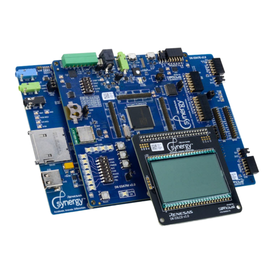
DK-S3A7 User’s Manual Getting Started > Resources > Power Chapter 2 Getting Started The DK-S3A7 includes the Main Board mounted on the Breakout Board together with the LCD panel. To start working with the DK-S3A7, see the Quick Start Guide included in the DK-S3A7 Kit. Figure 5: DK-S3A7 R12UM0003EU0100 Rev. -
Page 13: Chapter 3 Power Supplies
DK-S3A7 User’s Manual Power Supplies > Power supply > Power Chapter 3 Power Supplies 3.1 Power supply Power is supplied to the DK-S3A7 through a barrel connector on the Main Board using a 5-V/2.5-A, wall-mounted power supply. When +5 V is applied to J1, a green LED (LED3) illuminates on the main board. The DK-S3A7 Main Board includes a backup battery for powering the Realtime Clock (RTC) when no external power is supplied. -
Page 14: Battery Current
DK-S3A7 User’s Manual Power Supplies > Battery current > Power 3.5 Battery current You can monitor the VBAT current by measuring the voltage drop across the 1-kΩ resistor R41 using pins 2 and 3 of connector J23. In this setting, the voltage drop indicates the current consumption of the S3A7 microcontroller when the microcontroller is powered by the on-board coin cell battery. -
Page 15: Chapter 4 Components
Components > LCD Panel (LCD1) > Power Chapter 4 Components 4.1 LCD Panel (LCD1) The DK-S3A7 a Renesas 176-segment T6022A-1PRP0 LCD panel featuring: • Large 3-digit numerical display with decimal point • 5-digit numerical display with decimal point and clock colon • 6-digit alphanumeric display •... -
Page 16: Peripheral Devices
DK-S3A7 User’s Manual Components > Peripheral devices > Power 4.4 Peripheral devices • EEPROM (U108) – Device: OnSemi CAT24C64 – 8-KB CMOS serial EEPROM device, internally organized as 8192 words of 8 bits each. The EEPROM device features a 32−byte page write buffer and supports the Standard (100 kHz), Fast (400 kHz) and Fast−Plus (1 MHz) IIC protocol. - Page 17 DK-S3A7 User’s Manual Components > Peripheral devices > Power – The M25P20 is a 2-Mb (256 K x 8) serial flash memory device with advanced write protection mechanisms accessed by a high speed SPI-compatible bus. – The device supports high-performance commands for clock frequencies of up to 75 MHz. –...
-
Page 18: Chapter 5 Board Layout
DK-S3A7 User’s Manual Board Layout > Main Board components: > Power Chapter 5 Board Layout 5.1 Main Board components: Figure 6: Components: Main Board R12UM0003EU0100 Rev. 1.00 Page 18 of 41 5 Oct 2015 Arrow.com. Arrow.com. Arrow.com. Arrow.com. Arrow.com. Arrow.com. Arrow.com. -
Page 19: Breakout Board Components
DK-S3A7 User’s Manual Board Layout > Breakout Board components > Power 5.2 Breakout Board components Figure 7: Components: Breakout Board R12UM0003EU0100 Rev. 1.00 Page 19 of 41 5 Oct 2015 Arrow.com. Arrow.com. Arrow.com. Arrow.com. Arrow.com. Arrow.com. Arrow.com. Arrow.com. Arrow.com. Arrow.com. Arrow.com. -
Page 20: Chapter 6 Configuration
DK-S3A7 User’s Manual Configuration > Function select DIP switches > Power Chapter 6 Configuration The DK-S3A7 has the following configuration options: • DIP switch S5 for board function select • J4 analog enable for analog application header • Switch S6 for configuring the RS-232/485 transceiver for the serial connector J7 •... - Page 21 DK-S3A7 User’s Manual Configuration > Function select DIP switches > Power Figure 8: Function configuration R12UM0003EU0100 Rev. 1.00 Page 21 of 41 5 Oct 2015 Arrow.com. Arrow.com. Arrow.com. Arrow.com. Arrow.com. Arrow.com. Arrow.com. Arrow.com. Arrow.com. Arrow.com. Arrow.com. Arrow.com. Arrow.com. Arrow.com. Arrow.com. Arrow.com.
-
Page 22: Analog Enable Jumper
DK-S3A7 User’s Manual Configuration > Analog enable jumper > Power Table 1: Configuration Switch S5 DIP Switch Connector/ device Reference Push buttons QSPI QSPI flash RSXXX RS-232/485 BLE/Pmod B PMOD Pmod A JTAG JTAG BOOT Boot configuration 6.2 Analog enable jumper Analog signals on the Main Board analog I/O connector (J5) can be disabled individually through the configuration of jumper J4. -
Page 23: Usb Configuration
DK-S3A7 User’s Manual Configuration > USB configuration > Power Table 2: RS-232/485 (S6) configuration (Continued) SLEW Data rate Mode 460 kbps 20 Mbps 460 kbps 6.4 USB configuration DIP switch 5 (USBF) on S6 disables the USB Device connector (J2) on the Main Board. 6.5 Boot configuration By default, the S3A7 microcontroller boots from internal flash. -
Page 24: Chapter 7 Connectivity
DK-S3A7 User’s Manual Connectivity > Pmod A > Power Chapter 7 Connectivity 7.1 Pmod A To enable 12-pin Pmod Compatible connector Pmod A on the DK-S3A7 Main Board, use either of the following methods: • Set DIP switch 6 (PMOD) on S5 to ON. •... -
Page 25: Pmod C
DK-S3A7 User’s Manual Connectivity > Pmod C > Power Table 3: Pmod A connector (J20) (Continued) PMODA connector (Main Board) S3A7 microcontroller Description Function name PMODA_10 P713 (P7_13) GPIO ELATED LINKS Configuration 7.2 Pmod C Twelve-pin Pmod Compatible connector Pmod C provides access to the SPI0 peripheral or to SCI channel 0 on the S3A7 microcontroller. -
Page 26: Ble/Pmod B
DK-S3A7 User’s Manual Connectivity > BLE/Pmod B > Bluetooth 7.3 BLE/Pmod B The Bluetooth Low Energy (BLE) device and Pmod Compatible connector Pmod B both use the Serial Communication Interface (SCI) channel 1 of the S3A7 microcontroller. To use the Pmod B connector, disconnect the BLE device from the S3A7 microcontroller by setting switch 5 of DIP switch S5 to OFF. -
Page 27: Pmod B
DK-S3A7 User’s Manual Connectivity > RS-232/485 > Pmod B 7.3.2 Pmod B Twelve-pin Pmod Compatible connector Pmod B provides access to channel 1 of the Serial Communications Interface (SCI) peripheral on the S3A7 microcontroller, which can be configured through software as SPI, UART, or IIC-bus interface (IIC Fast mode and Standard mode only). -
Page 28: Can
DK-S3A7 User’s Manual Connectivity > CAN > Pmod B The RS-232/485 signals are controlled by the RS-232/485 transceiver (U19) on Main Board. The transceiver uses channel 2 of the Serial Communication Interface (SCI) on the S3A7 microcontroller, which must be configured through software as a UART interface. -
Page 29: User Leds
DK-S3A7 User’s Manual Connectivity > User LEDs > Pmod B Table 8: CAN transceiver (U21) CAN transceiver (Main Board) S3A7 microcontroller Description Function name CAN_TX CAN Transmit P401 (P4_1) CTX0 CAN_RX CAN Receive P402 (P4_2) CRX0 ELATED LINKS Configuration Pin mapping 7.6 User LEDs The Main Board features two LEDs that can be controlled by the application through the GPIO pins of the S3A7 microcontroller. -
Page 30: Jtag
DK-S3A7 User’s Manual Connectivity > JTAG > Pmod B The Main Board features three push buttons, which are connected to the external interrupt inputs of the S3A7 microcontroller. Table 10: Push buttons Push buttons (Main Board) S3A7 microcontroller Description Function name IRQ8 P305 (P3_5) IRQ8... -
Page 31: Capacitive Touch Expansion
DK-S3A7 User’s Manual Connectivity > Capacitive touch expansion > Pmod B Table 11: JTAG (Continued) JTAG (Main Board) S3A7 microcontroller Description Function name RESET# Reset RESET# RESET# ELATED LINKS Pin mapping Configuration 7.9 Capacitive touch expansion The Main Board includes a capacitive-touch expansion port, which is compatible with the RX113 Capacitive-Touch Kit. The expansion port consists of two connectors, J18 and J19. -
Page 32: Qspi Flash
DK-S3A7 User’s Manual Connectivity > QSPI flash > Pmod B Table 12: Capacitive touch expansion connector (J18) (Continued) Capacitive touch connector (Main Board) S3A7 microcontroller Description Function name TS10 P403 (P4_3) TS17 TS11 P400 (P4_0) TS20 TS ID P010 (P010) Table 13: I/O Expansion Controller (U22) for capacitive touch expansion connector (J19) I/O Expansion Controller S3A7 microcontroller... -
Page 33: Analog I/O
DK-S3A7 User’s Manual Connectivity > Analog I/O > Pmod B Table 15: QSPI flash (U10) QSPI flash (Main Board) S3A7 microcontroller Description Function name QSPI CS# P501 (P5_1) QSSL QSPI CLK P500 (P5_0) QSPCLK QSPI DQ0 P502 (P5_2) QIO0 QSPI DQ1 P503 (P5_3) QIO1 QSPI DQ2... -
Page 34: Chapter 8 Appendix
DK-S3A7 User’s Manual Appendix > Pin mapping > Pmod B Chapter 8 Appendix 8.1 Pin mapping The following table shows the routing of the microcontroller pins between the Main Board and the Breakout Board. All microcontroller pins are accessible on the breakout pin connectors J7 to J9 on the Main Board. The microcontroller pins are also routed to the Breakout Board through board-to-board connectors as needed for the Breakout Board functions. - Page 35 DK-S3A7 User’s Manual Appendix > Pin mapping > Pmod B Table 17: Main Board to Breakout Board pin mapping (Continued) S3A7 microcontroller Main Board Breakout Board Breakout Application Other connectors or Port pin pins Other connectors or devices header pins devices P012 (P0_12) J7/13...
- Page 36 DK-S3A7 User’s Manual Appendix > Pin mapping > Pmod B Table 17: Main Board to Breakout Board pin mapping (Continued) S3A7 microcontroller Main Board Breakout Board Breakout Application Other connectors or Port pin pins Other connectors or devices header pins devices P201 (P2_1) J7/34...
- Page 37 DK-S3A7 User’s Manual Appendix > Pin mapping > Pmod B Table 17: Main Board to Breakout Board pin mapping (Continued) S3A7 microcontroller Main Board Breakout Board Breakout Application Other connectors or Port pin pins Other connectors or devices header pins devices P312 (P3_12) J9/13...
- Page 38 DK-S3A7 User’s Manual Appendix > Pin mapping > Pmod B Table 17: Main Board to Breakout Board pin mapping (Continued) S3A7 microcontroller Main Board Breakout Board Breakout Application Other connectors or Port pin pins Other connectors or devices header pins devices P501 (P5_1) J9/34...
- Page 39 DK-S3A7 User’s Manual Appendix > Pin mapping > Pmod B Table 17: Main Board to Breakout Board pin mapping (Continued) S3A7 microcontroller Main Board Breakout Board Breakout Application Other connectors or Port pin pins Other connectors or devices header pins devices P611 (P6_11) J8/11...
- Page 40 DK-S3A7 User’s Manual Appendix > Pin mapping > Pmod B Table 17: Main Board to Breakout Board pin mapping (Continued) S3A7 microcontroller Main Board Breakout Board Breakout Application Other connectors or Port pin pins Other connectors or devices header pins devices P805 (P8_5) J8/32...
- Page 41 DK-S3A7 User’s Manual Appendix > Pin mapping > Pmod B R12UM0003EU0100 Rev. 1.00 Page 41 of 41 5 Oct 2015 Arrow.com. Arrow.com. Arrow.com. Arrow.com. Arrow.com. Arrow.com. Arrow.com. Arrow.com. Arrow.com. Arrow.com. Arrow.com. Arrow.com. Arrow.com. Arrow.com. Arrow.com. Arrow.com. Arrow.com. Arrow.com. Arrow.com. Arrow.com. Arrow.com.
- Page 42 Revision Record Description Revision Date Page Summary 0.10 March 2015 First preliminary version 0.50 July 2015 Editorial updates 1.00 Oct. 2015 Updated for DK-S3A7 v2 Arrow.com. Arrow.com. Arrow.com. Arrow.com. Arrow.com. Arrow.com. Arrow.com. Arrow.com. Arrow.com. Arrow.com. Arrow.com. Arrow.com. Arrow.com. Arrow.com. Arrow.com. Arrow.com.
- Page 43 Renesas Synergy DK-S3A7 User’s Manual Publication Date: Rev. 1.00 October, 2015 Arrow.com. Arrow.com. Arrow.com. Arrow.com. Arrow.com. Arrow.com. Arrow.com. Arrow.com. Arrow.com. Arrow.com. Arrow.com. Arrow.com. Arrow.com. Arrow.com. Arrow.com. Arrow.com. Arrow.com. Arrow.com. Arrow.com. Arrow.com. Arrow.com. Arrow.com. Arrow.com. Arrow.com. Arrow.com. Arrow.com. Arrow.com. Arrow.com. Arrow.com.
- Page 44 SALES OFFICES Refer to "http://www.renesas.com/" for the latest and detailed information. Renesas Electronics America Inc. 2801 Scott Boulevard Santa Clara, CA 95050-2549, U.S.A. Tel: +1-408-588-6000, Fax: +1-408-588-6130 Renesas Electronics Canada Limited 9251 Yonge Street, Suite 8309 Richmond Hill, Ontario Canada L4C 9T3...
- Page 45 Renesas Synergy DK-S3A7 User’s Manual R12UM0003EU0100 Arrow.com. Arrow.com. Arrow.com. Arrow.com. Arrow.com. Arrow.com. Arrow.com. Arrow.com. Arrow.com. Arrow.com. Arrow.com. Arrow.com. Arrow.com. Arrow.com. Arrow.com. Arrow.com. Arrow.com. Arrow.com. Arrow.com. Arrow.com. Arrow.com. Arrow.com. Arrow.com. Arrow.com. Arrow.com. Arrow.com. Arrow.com. Arrow.com. Arrow.com. Arrow.com. Arrow.com. Arrow.com. Arrow.com. Arrow.com.
Need help?
Do you have a question about the Synergy DK-S3A7 and is the answer not in the manual?
Questions and answers