Renesas Synergy SK-S7G2 User Manual
Starter kit for synergy s7g2 mcu
Hide thumbs
Also See for Synergy SK-S7G2:
- Quick start manual (16 pages) ,
- Quick start manual (5 pages) ,
- User manual (31 pages)
Table of Contents
Advertisement
Quick Links
Renesas Synergy™
Starter Kit SK-S7G2
Synergy S7G2 MCU
All information contained in these materials, including products and product specifications,
represents information on the product at the time of publication and is subject to change by
Renesas Electronics Corp. without notice. Please review the latest information published by
Renesas Electronics Corp. through various means, including the Renesas Electronics Corp.
website (http://www.renesas.com).
www.renesas.com
Arrow.com.
Downloaded from
User's Manual
Rev.1.00 Oct. 2015
Advertisement
Table of Contents

Related Manuals for Renesas Synergy SK-S7G2


Summary of Contents for Renesas Synergy SK-S7G2
- Page 1 All information contained in these materials, including products and product specifications, represents information on the product at the time of publication and is subject to change by Renesas Electronics Corp. without notice. Please review the latest information published by Renesas Electronics Corp. through various means, including the Renesas Electronics Corp.
- Page 2 Renesas Electronics products are not subject to radiation resistance design. Please be sure to implement safety measures to guard them against the possibility of physical injury, and injury or damage caused by fire in the event of the failure of a Renesas Electronics product, such as safety design for hardware and software including but not limited to redundancy, fire control and malfunction prevention, appropriate treatment for aging degradation or any other appropriate measures.
-
Page 3: Table Of Contents
Table of Contents 1. Overview ............................1 Features ..................................1 In the box .................................. 1 Block diagram ................................2 Hardware features ..............................2 Resources .................................. 2 2. Getting Started ........................... 3 3. Power Supply Requirements ......................4 Power supply ................................4 Power-up behavior .............................. -
Page 4: Overview
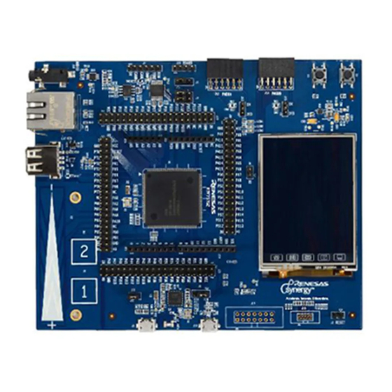
Overview Features The SK-S7G2 is a single-board starter kit for the Renesas Synergy S7G2 microcontroller in a 176-pin LQFP package. The board provides easy-to-access interfaces to the peripherals of the S7G2 microcontroller for application development. The SK-S7G2 includes four header connectors for direct access to the S7G2 microcontroller I/O pins. Additionally, the board includes connectors for USB, Ethernet, RS-232/485, CAN, and JTAG J-Link interfaces. -
Page 5: Block Diagram
SK-S7G2 1. Overview Block diagram Figure 2: SK-S7G2 block diagram Hardware features The SK-S7G2 contains the following hardware: • S7G2 microprocessor with 176 LQFP package • Four connectors that provide access to all S7G2 microprocessor signals • Low cost QVGA TFT touch screen •... -
Page 6: Getting Started
SK-S7G2 2. Getting Started Getting Started To start working with the SK-S7G2, see the Quick Start Guide included in the kit. R12UM0004EU0100 Rev.1.00 Page 3 of 22 October 8, 2015 Arrow.com. Arrow.com. Arrow.com. Arrow.com. Arrow.com. Arrow.com. Downloaded from Downloaded from Downloaded from Downloaded from Downloaded from... -
Page 7: Power Supply Requirements
SK-S7G2 3. Power Supply Requirements Power Supply Requirements Power supply Power is supplied to the SK-S7G2 through the debug USB connector (J19). The SK-S7G2 requires 5V applied on this interface (USB standard). Once power is supplied, the power supply indicator LED4 will light green. Power-up behavior When power is applied to the SK-S7G2, the power-on reset (POR) monitor of the S7G2 microcontroller resets the S7G2. - Page 8 SK-S7G2 3. Power Supply Requirements Figure 5: Measuring digital current consumption on S7G2 microcontroller Power consumption for the analog supply of the S7G2 microcontroller requires removing resistor R114 and measuring current across it. Figure 6: Measuring analog current consumption on S7G2 microcontroller R12UM0004EU0100 Rev.1.00 Page 5 of 22 October 8, 2015...
-
Page 9: Board Components
SK-S7G2 4. Board Components Board Components J-Link On-Board debugger The SK-S7G2 features a SEGGER J-Link On-Board debugger, accessible through the J19 USB connector. Alternatively, the onboard debugger can be bypassed by removing resistors R107, R108, R109, and R110. Once removed, JTAG/SWD debugging can then be done through the J18 header. -
Page 10: Ethernet
SK-S7G2 4. Board Components Figure 8: LCD interface mode selection Touch-screen sensing is through a Semtech SX8656 resistive touch-screen controller, connected to the S7G2 microcontroller through an IIC bus. Figure 9: Touch-screen controller Ethernet The SK-S7G2 includes a Micrel KSZ8081 10/100 Ethernet physical interface. Ethernet connection is through the RJ-45 standard connector J11. -
Page 11: Can, Rs-232/485
SK-S7G2 4. Board Components PMODB, available on the J14 connector, exposes a UART, three GPIO lines, and an interrupt line to the S7G2 microcontroller. Figure 11: PMODB interface Both PMOD interfaces can output either 5V or 3.3V, depending on the position of the J13 and J15 jumpers. CAN, RS-232/485 The SK-S7G2 includes a UART interface (either RS-232 or RS-485) and a CAN interface. -
Page 12: Usb Device Port
SK-S7G2 4. Board Components USB Device port The SK-S7G2 is equipped with a USB Full-Speed (12-Mbps) Device port on J5. The SK-S7G2 cannot be powered through this interface (power still needs to be applied through the USB device port J19), but connection to this port can be detected since the power pin of this port is connected to a microcontroller GPIO. -
Page 13: Audio
SK-S7G2 4. Board Components Audio The SK-S7G2 contains an amplified mono audio output on a standard 3.5mm audio jack J16. The audio is generated with the S7G2 D/A converter on output DA0, and the amplification gain can be changed by modifying resistor pairs R70/R71 and R73/R72. -
Page 14: Arduino Shield Interface
SK-S7G2 4. Board Components Figure 18: QSPI flash 4.12 Arduino Shield interface The SK-S7G2 includes one Arduino Shield compatible interface, so that Arduino Shield boards can expand the SK-S7G2 functionality. The Arduino Shield interface is implemented with the J24, J25, J26, and J27 connectors. Figure 19: Arduino Shield interface 4.13 Breakout headers... - Page 15 SK-S7G2 4. Board Components Figure 20: S7G2 microcontroller breakout headers R12UM0004EU0100 Rev.1.00 Page 12 of 22 October 8, 2015 Arrow.com. Arrow.com. Arrow.com. Arrow.com. Arrow.com. Arrow.com. Arrow.com. Arrow.com. Arrow.com. Arrow.com. Arrow.com. Arrow.com. Arrow.com. Arrow.com. Arrow.com. Downloaded from Downloaded from Downloaded from Downloaded from Downloaded from Downloaded from...
-
Page 16: Board Layout
SK-S7G2 5. Board Layout Board Layout The SK-S7G2 board measures 145mm x 120mm. Figure 21 shows the location of all the relevant board components described in the prior section. Figure 21: SK-S7G2 component placement R12UM0004EU0100 Rev.1.00 Page 13 of 22 October 8, 2015 Arrow.com. -
Page 17: Configuration
SK-S7G2 6. Configuration Configuration The SK-S7G2 kit has several configuration options set by jumpers. Table 1 lists the different jumpers and their positions. Table 1: SK-S7G2 configuration jumpers Jumper Function S7G2 boot selection. If J1 is in position 1-2 (default), the MCU boots in normal mode (from its ROM). -
Page 18: Connectivity
SK-S7G2 7. Connectivity Connectivity The following sections describe in detail the interfaces available on the SK-S7G2, detailing the MCU resources utilized in each. USB Host port The SK-S7G2 includes one USB Host/High-Speed port (J6). This port supplies current to devices connected to it through a current limited power switch (U14). -
Page 19: Lcd
SK-S7G2 7. Connectivity Table 5: Ethernet functions S7G2 Pin Function name P010 ETH_IRQ14# P806 ETH_RESET# P403 ETH_MDC P404 ETH_MDIO P705 ETH_CRS_DV P405 ETH_TXD_EN P700 ETH_TDX0 P406 ETH_TXD1 P702 ETH_RXD0 P703 ETH_RXD1 P704 ETH_RX_ER P701 ETH (Reference Clock) The SK-S7G2 includes a 240x320 QVGA LCD panel with touch-screen interface. This display is connected directly to the S7G2’s display port, and through a touchscreen controller IC to the display’s touch-screen interface. -
Page 20: Pmod Compatible Ports
SK-S7G2 7. Connectivity Table 6: LCD functions (J3) S7G2 Pin Function name P610 LCD_RESET P314 LCD_VSYNC P313 LCD_HSYNC P900 LCD_CLK_B P315 LCD_Data_Enable P901 LCD_D15 P908 LCD_D14 P907 LCD_D13 P906 LCD_D12 P905 LCD_D11 P615 LCD_D10 PA08 LCD_D9 PA09 LCD_D8 PA10 LCD_D7 PA01 LCD_D6 PA00... -
Page 21: Jtag/Swd
SK-S7G2 7. Connectivity Table 8: PMODA port functions S7G2 Pin Function name P103 SSLA0_A P101 MOSIA_A P100 MISOA_A P102 RSPCK_A P111 IRQ4# P310 GPIO (PMOD pin 4) P311 GPIO (PMOD pin 6) P312 GPIO (PMOD pin 8) Table 9: PMODB port functions S7G2 Pin Function name P413... - Page 22 SK-S7G2 7. Connectivity Table 11: UART interface functions S7G2 Pin Function name P706 UART_RXD P707 UART_TXD P801 INVALID P800 READY (RS-232) or RE (RS-485) Table 12: CAN interface functions S7G2 Pin Function name P401 CAN_TX P402 CAN_RX R12UM0004EU0100 Rev.1.00 Page 19 of 22 October 8, 2015 Arrow.com.
-
Page 23: Pin Connections
SK-S7G2 8. Pin Connections Pin Connections Table 13 shows the connection of S7G2 pins to SK-S7G2 functions. Table 13: Pin connections S7G2 Pin Peripheral Signal SK-S7G2 connector P000 Arduino Shield AN000 J26 (1) P001 Arduino Shield AN001 J26 (2) P002 Arduino Shield AN002 J26 (3) - Page 24 SK-S7G2 8. Pin Connections S7G2 Pin Peripheral Signal SK-S7G2 connector P310 PMODA J12 (4) P311 PMODA J12 (6) P312 PMODA J12 (8) P313 LCD_HSYNC J3 (40) P314 LCD_VSYNC J3 (41) P315 LCD_Data_Enable J3 (38) P400 PMODB IRQ0# J14 (2) P401 CAN_TX P402 CAN_RX...
- Page 25 SK-S7G2 8. Pin Connections S7G2 Pin Peripheral Signal SK-S7G2 connector P608 Arduino Shield J27 (6) P609 LCD (Touchscreen) RESET# P613 Arduino Shield J27 (7) P614 Arduino Shield J27 (8) P615 LCD_D10 J3 (31) P700 Ethernet ETH_TXD0 P701 Ethernet P702 Ethernet ETH_RXD0 P703 Ethernet...
- Page 26 SK-S7G2 User’s Manual Revision History Rev. Date Description Page Summary 1.00 Oct. 2015 First Edition issued C - 1 Arrow.com. Arrow.com. Arrow.com. Arrow.com. Arrow.com. Arrow.com. Arrow.com. Arrow.com. Arrow.com. Arrow.com. Arrow.com. Arrow.com. Arrow.com. Arrow.com. Arrow.com. Arrow.com. Arrow.com. Arrow.com. Arrow.com. Arrow.com. Arrow.com.
- Page 27 Sk-S7G2 User’s Manual Publication Date: Rev.1.00 Oct. 2015 Published by: Renesas Electronics Corporation Arrow.com. Arrow.com. Arrow.com. Arrow.com. Arrow.com. Arrow.com. Arrow.com. Arrow.com. Arrow.com. Arrow.com. Arrow.com. Arrow.com. Arrow.com. Arrow.com. Arrow.com. Arrow.com. Arrow.com. Arrow.com. Arrow.com. Arrow.com. Arrow.com. Arrow.com. Arrow.com. Arrow.com. Arrow.com. Arrow.com. Arrow.com.
- Page 28 SALES OFFICES Refer to "http://www.renesas.com/" for the latest and detailed information. Renesas Electronics America Inc. 2801 Scott Boulevard Santa Clara, CA 95050-2549, U.S.A. Tel: +1-408-588-6000, Fax: +1-408-588-6130 Renesas Electronics Canada Limited 9251 Yonge Street, Suite 8309 Richmond Hill, Ontario Canada L4C 9T3...
- Page 29 Renesas Synergy SK-S7G2 User’s Manual R12UM0004EU0100 Arrow.com. Arrow.com. Arrow.com. Arrow.com. Arrow.com. Arrow.com. Arrow.com. Arrow.com. Arrow.com. Arrow.com. Arrow.com. Arrow.com. Arrow.com. Arrow.com. Arrow.com. Arrow.com. Arrow.com. Arrow.com. Arrow.com. Arrow.com. Arrow.com. Arrow.com. Arrow.com. Arrow.com. Arrow.com. Arrow.com. Arrow.com. Arrow.com. Arrow.com. Downloaded from Downloaded from Downloaded from...
Need help?
Do you have a question about the Synergy SK-S7G2 and is the answer not in the manual?
Questions and answers