
Related Manuals for SEA TAURUS RACK Series


Summary of Contents for SEA TAURUS RACK Series
- Page 1 TA R S RAC TA R S C AIN MOTOR REDUCERS 2 FOR SLIDIN ATES SEA USA Inc. 10850 N.W. 21st - unit 160 - DORAL - MIAMI Florida (FL) 33172 Phone: ++1-305.594.1151 Toll Free: 800.689.4716 www.sea-usa.com 67411231 Re . 03 - 12 2019...
- Page 2 ORTANT SA ETY IN OR ATION GENERAL SAFETY PRECAUTIONS The following precautions are an integral and essential part of the product and must be supplied to the user Read them carefully as they contain important indications for the safe installation, use and maintenance. .
-
Page 3: General Safety Information
GENERAL SAFETY INFORMATION An appliance shall be provided with an instruction manual. The instruction manual shall give instructions for the installation, operation, and user maintenance of the appliance. The installation instructions shall specify the need for a grounding-type receptacle for connection to the supply and shall stress the importance of proper grounding. - Page 4 The installer shall follow the provided instructions thoroughly. SEA products must only be used to automate doors, gates and wings. Any initiative taken without SEA USA Inc. explicit authorization will preserve the manufacturer from whatsoever responsibility.
- Page 5 5. The End of T pe E. Type E audible alarm devices can no longer be used for entrapment protection. This change was made because the Type E device is really a warning device, not an entrapment-protection device. Also, all gate operator classes are now required to have an audio alarm that sounds when two successive obstructions are encountered via a contact-type system.
- Page 6 ATE WARNIN S AND RECA TIONS GATE ARRANGEMENT Check the gate is in good running order as follows: a) The gate is rigid and straight and runs smoothly throughout its travel b) The inferior sliding guide-rail is perfectly straight and horizontal to avoid derailment of the gate Fig. furthermore it must be free of irregularities and foreign bodies which could obstruct the normal run of the gate Fig.
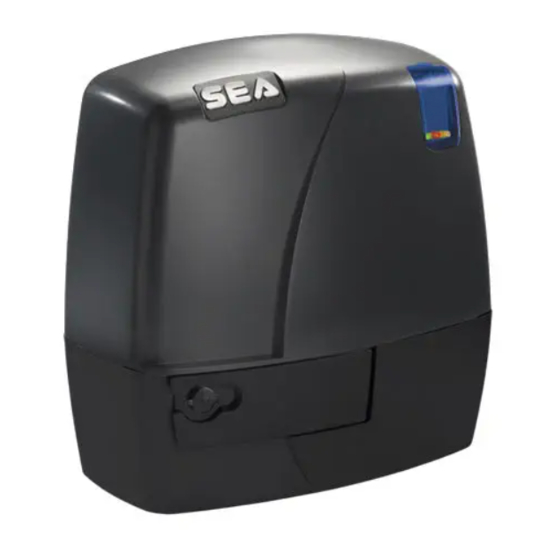
- Page 7 AIN EAT RES TAURUS is a sliding gate operator with grease lubricated gear. The irre ersibilit of the motor grants a perfect and safe gate closing, avoiding the need of an elecric lock. In case of electric power failure, the manual release handle placed head on the operator allows the manual opening and closing of the gate.
- Page 8 EC ANICAL INSTALLATION 1. TYPE OF INSTALLATION Fig. 5 O er- Tra el Only a head-on installation of the operator is Stop permitted it is highly recommended to install two security gate stops on the two extremities of the rail to prevent the gate from derailment Fig.
- Page 9 5. GEAR RAC MOUNTING (Only for TAURUS RACK version) 5.1. Release the motor and open the leaf completely 5.2. Fix on each gear rack element the support pawls with the appropriate lock screws, make sure to put Steel rac them in the upper part of the hole Fig. 2 Plastic rac (to weld) steel core...
- Page 10 6. ASSEM LING OF T E C AIN SYSTEM (Only for TAURUS CHAIN version) The assembling of the main parts which include the whole chain automation is illustrated in Fig. 26. In the Fig. 27 and 2 it is possible to see the correct instal- lation with open and closed gate respectively make sure the chain runs inside the pinion group which must not be modified.
- Page 11 8. GROUNDING (Fig. 35) 7. LIMIT SWITC AD USTMENT For versions «TAURUS WITH LIMIT SWITCH» 7.1. To install and adjust the limit switches in opening proceed as follows Fig. 32 : - Completely open the gate - Place the plate on the rack in order to have the lever of the mechanical limit switch Fig.
-
Page 12: Periodic Maintenance
NOTE: T E MANUFACTURER S ALL NOT S OULDER ANY RESPONSI ILITIES IN CASE OF DAMAGE CAUSED NAPPROPRIATE WRONG OR CARELESS USE. SEA reserves the right to make all the necessary changes and modifications of the products or manuals without giving prior notice... - Page 13 PAYMENT: Method of payments and terms are notified by SEA and displayed on the commercial invoice. DELIVERY: The delivery time on the invoice is not binding and represents an estimated delivery. Shipments costs will be charged to the buyer and SEA is not responsible for delays and/or damages occurred to the products during shipment.
- Page 14 NOTES...
- Page 16 SEA USA Inc. 10850 N.W. 21st - unit 160 - DORAL - MIAMI Florida (FL) 33172 Phone: ++1-305.594.1151 Toll Free: 800.689.4716 www.sea-usa.com sales@sea-usa.com...
Need help?
Do you have a question about the TAURUS RACK Series and is the answer not in the manual?
Questions and answers