Advertisement
1. INTRODUCTION
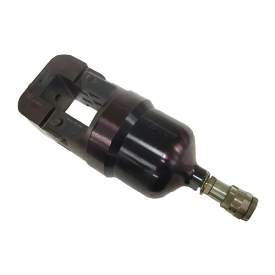
This instruction sheet covers application, inspection and maintenance procedures for Crimping Heads 58422-1
1
and 2161730-1
shown typically in Figure 1. The crimping heads use interchangeable crimping dies used to
crimp a variety of heavy-duty terminals and splices for large wire sizes (Size 8 thru 4/0 AWG) as listed in Figure
2. This instruction sheet provides general information for the insertion of dies and the crimping procedure.
Always refer to the instructions packaged with specific die sets for compatible products, wire ranges, strip
dimensions, and application procedures.
This crimping heads are designed for two DYNA-CRIMP* tools: either Hydraulic Hand Pump 314979-1
described in Customer Manual 409-5860; or Hydraulic Power Unit 69120-[ ] described in Customer Manual
409-1950.
Warning: To avoid personal injury and potential damage to the crimp head, TE Connectivity (TE) requires the
crimp head to operate at 8,000 to 8,400 PSI [552 to 579 bar]. TE recommends using 8,200 PSI [565 bar] TE
Hydraulic Pumps as other manufacturers' pumps may apply insufficient pressure (resulting in an inadequate
crimp) or excessive pressure (resulting in failure of the head). Additionally, the TE pump must be used to
maintain CE certification; if using other manufacturers' pumps, the user is responsible for self-certification.
Read these instructions and other applicable references carefully before proceeding.
1 Part Number 2161730-1 is a special version of PN 58422-1, with an extended stroke for terminating sealed COPALUM quick-termination connectors.
© 2017 TE Connectivity Ltd. family of companies.
All Rights Reserved.
*Trademark
TE Connectivity, TE connectivity (logo), and TE (logo) are trademarks. Other logos, product, and/or company names may be trademarks of their respective owners.
Hydraulic Crimping Heads
58422-1 and 2161730-1
Figure 1
Products Crimped
AMPLI-BOND* and PLASTI-GRIP* Terminals
TERMINYL* Terminals and Splices
Pre-Insulated AMPOWER* Terminals
Pre-Insulated Nylon Heavy Duty Terminals
COPALUM* Sealed Terminals and Splices
Figure 2
PRODUCT INFORMATION 1-800-522-6752
This controlled document is subject to change.
For latest revision and Regional Customer Service,
visit our website at www.te.com.
Instruction Sheet
408-9535
30 MAY 17 REV D
1 of 6
Advertisement
Table of Contents

Related Manuals for TE Connectivity 58422-1


Summary of Contents for TE Connectivity 58422-1
- Page 1 1 of 6 All Rights Reserved. For latest revision and Regional Customer Service, visit our website at www.te.com. *Trademark TE Connectivity, TE connectivity (logo), and TE (logo) are trademarks. Other logos, product, and/or company names may be trademarks of their respective owners.
- Page 2 408-9535 NOTE Dimensions in this instruction sheet are in millimeters [with inches in brackets]. Illustrations and figures are for reference only and are not drawn to scale. Reasons for reissue of this Instruction Sheet are provided in Section 8; REVISION SUMMARY. 2.
- Page 3 408-9535 Figure 3 2. Loosen setscrew in yoke. Refer to die set instructions and insert stationary (upper) die which includes the nest area into well of yoke. Tighten setscrew. 3. Activate power unit to advance ram until setscrew is visible (about 12.7 mm [.50 in.]). Loosen setscrew.
- Page 4 Verify hydraulic pressure is released and power supply is disconnected before following inspection and maintenance procedures, unless otherwise specified in the procedure. Each crimping head is assembled and inspected before shipment. TE Connectivity recommends that the crimping head be inspected immediately upon its arrival at the facility of use, and at regularly scheduled intervals, to ensure the head has not been damaged during handling and use.
- Page 5 1-800-526-5142, or send a facsimile of your purchase order to 1-717-986-7605, or write, or return the entire tool for evaluation and repair, with a written description of the problem to: CUSTOMER SERVICE (38-35) TE CONNECTIVITY CORPORATION P.O. BOX 3608 HARRISBURG, PA 17105-3608 Tools may also be returned for evaluation and repair.
- Page 6 408-9535 Item Quantity Part Number Description Number Per Head 311471-1 Coupler, Quick Connect / Disconnect 306209-8 Pin, Removable Latch 8-59558-5 Pin, Pivot 1-21045-1 Ring, Retaining 4-21012-0 Setscrew 4-23147-7 Spring, Compression 1-21919-6 Pin, Dowel Figure 5 6 of 6 Rev D...
Need help?
Do you have a question about the 58422-1 and is the answer not in the manual?
Questions and answers