Advertisement
Quick Links
PROPER USE GUIDELINES
Cumulative Trauma Disorders can result from the prolonged use of manually powered hand tools. Hand tools are intended for occasional use
and low volume applications. A wide selection of powered application equipment for extended-use, production operations is available.
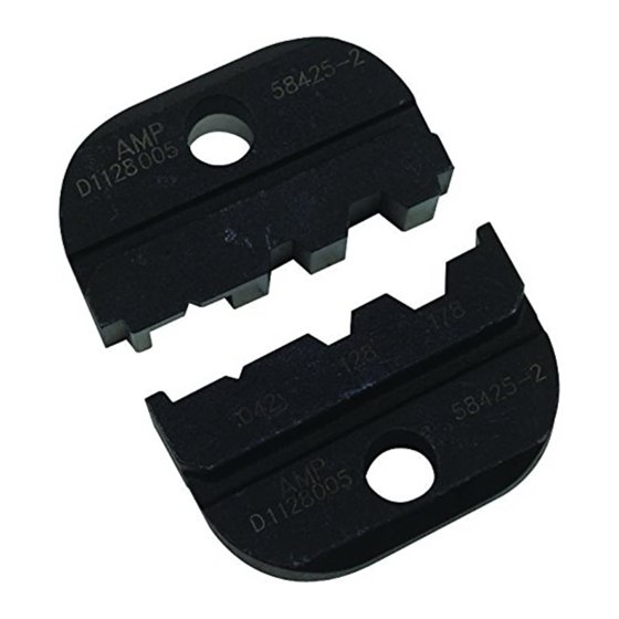
Anvil Die
Die Assemblies 58425-[ ]
and 58436-[ ]
Indenter Die
1. INTRODUCTION
This instruction sheet covers the use and maintenance
of Crimping Dies 58425-[ ] and58436-[ ] (in their
various configurations - denoted by the dash number
following the base part number), used in PRO-
CRIMPER III Hand Tool Frame 354940-1. The dies
crimp 75-Ohm Hex Crimp BNC and TNC plug
connectors onto coaxial cable.
Reasons for reissue of this sheet are provided in
Section 7, REVISION SUMMARY.
All dimensions are in millimeters [with inches in
NOTE
brackets]. Figures and illustrations are for
reference only and are not drawn to scale.
i
© 2011 Tyco Electronics Corporation, a TE Connectivity Ltd. Company
All Rights Reserved
*Trademark
TE Connectivity, TE connectivity (logo), and TE (logo) are trademarks. Other logos, product and/or Company names may be trademarks of their respective owners.
75-Ohm Hex Crimp
Die Assemblies
58425-[ ] and 58436-[ ]
Stationary Jaw
Moving Jaw
Figure 1
TOOLING ASSISTANCE CENTER 1-800-722-1111
PRODUCT INFORMATION 1-800-522-6752
2. DESCRIPTION
(Figure 1
Each die assembly consists of an indenter die and an
anvil die. When closed, the dies form either two or
three crimping chambers (depending on type) which
crimp the center contact and ferrule of the connector
onto the coaxial cable. Each die is held in the tool by a
single screw.
3. DIE INSTALLATION
1. Close the tool handles until the ratchet releases
and then allow them to open fully.
2. See Figure 1 for normal orientation of the dies.
Insert the dies inside the tool jaws and align the
retaining screw holes.
3. Thread the retaining screws into the holes and
carefully close the tool handles. Tighten the screws
with the appropriate hex wrench.
This controlled document is subject to change.
For latest revision and Regional Customer Service,
visit our website at www.te.com
Instruction Sheet
408-9657
14 OCT 11 Rev E
Hand Tool Frame
354940-1
)
1 of 4
LOC B
Advertisement

Related Manuals for TE Connectivity 58425 Series


Summary of Contents for TE Connectivity 58425 Series
- Page 1 PRODUCT INFORMATION 1-800-522-6752 For latest revision and Regional Customer Service, *Trademark visit our website at www.te.com LOC B TE Connectivity, TE connectivity (logo), and TE (logo) are trademarks. Other logos, product and/or Company names may be trademarks of their respective owners.
- Page 2 408-9657 Insert Center Contact Flange on End of Center Center Contact into Partially Closed Contact Butts Against Die Slipped Over Crimping Dies Center Conductor Flange on End of Contact Crimping Die Ferrule Figure 3 (Ref) Damaged product should not be used. If a CAUTION damaged contact or ferrule is evident, it should be Figure 2...
- Page 3 408-9657 Die 58425-[ ] Die 58436-[ ] CHAMBER CRIMP DIMENSION ±0.10 [.004] DIE ASSEMBLY PART NUMBER “A" “B” “C” “D” 58425-1 1.07 [.042] (Square) 5.41 [.213] (Hex) 6.48 [.255] (Hex) 58425-2 1.07 [.042] (Square) 3.25 [.128] (Hex) 4.52 [.178] (Hex) 58425-3 1.07 [.042] (Square) 3.84 [.151] (Hex)
- Page 4 408-9657 This Tooling is also Compatible with Die Assemblies 58425-[ ] and 58436-[ ] PRO-CRIMPER III Hand Tool Frame 354940-1 SDE-SA Hand Tool 9-1478240-0 (Instruction Sheet 408-9930) (Instruction Sheet 408-8851) SDE Bench Terminator 1490076-2 626 Adapter 679304-1 (Customer Manual 409-10052) (Instruction Sheet 408-4070) Electro-Hydraulic (BT 3500 Battery-Hydraulic) Closed Head Assembly 2031460-1...
Need help?
Do you have a question about the 58425 Series and is the answer not in the manual?
Questions and answers