Advertisement
PROPER USE GUIDELINES
Cumulative Trauma Disorders can result from the prolonged use of manually powered hand tools. Hand tools are intended for occasional use and low
volume applications. A wide selection of powered application equipment for extended-use, production operations is available.
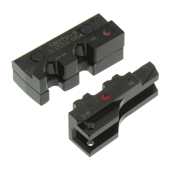
Wire Size
Range Markings
Crimping
Chamber
1. INTRODUCTION
This instruction sheet covers application and maintenance procedures for Crimping Die Assemblies 58079-3
and 58080-3. See Figure 1. Each die assembly is used with Hand Crimping Tool Frame 58078-3, which will
crimp the Ultra-Fast Plus Fully Insulated FASTON* Terminals listed in Figure 2.
Refer to Instruction Sheet
number information is available in Catalog 82004.
NOTE
Dimensions are in millimeters [with inch equivalents in brackets]. Figures are for identification only and are not drawn to scale.
Reasons for reissue are provided in Section 7, REVISION SUMMARY.
2. DESCRIPTION
Each die assembly consists of an upper die (crimper) and a lower die (anvil), a die retention screw (on upper
die), and a hex wrench for securing the socket head setscrew to the lower die and onto the hand tool platform.
When mated, the dies form two crimping chambers, each marked with the wire size range.
The die assemblies are identified by the part number, color dot code, and applicable wire range markings.
Refer to Figure 2. The color dot code on the die assembly must match the color-coded terminal.
3. DIE ASSEMBLY INSTALLATION
3.1. Installing Lower Die
1. Close tool frame handles until ratchet releases, then allow handles to open FULLY.
2. Slide lower die onto lower jaw platform of tool frame. Make sure that the hole on the side of the lower
die aligns with the socket head setscrew already installed in the lower jaw platform. See Figure 3.
NOTE
If lower die will not position properly, use hex wrench provided with die assembly to turn socket head setscrew either in or out
until lower die positions properly. The setscrew must be flush on both sides.
3. Using hex wrench, turn socket head setscrew CLOCKWISE until snug. Do NOT over-tighten.
© 2015 TE Connectivity family of companies
All Rights Reserved
*Trademark
TE Connectivity, TE connectivity (logo), and TE (logo) are trademarks. Other logos, product, and/or company names may be trademarks of their respective owners.
Crimping Die Assemblies
58079-3 and 58080-3
Upper Die
(Crimper)
Hex Wrench
Access Hole
Wire Size Range Markings
408-6976
(supplied with tool frame) for specific tooling information. Product part
PRODUCT INFORMATION 1-800-522-6752
Die Retention
Screw
Color Dot Code
Figure 1
This controlled document is subject to change.
For latest revision and Regional Customer Service,
visit our website at www.te.com.
Instruction Sheet
408-9278
21 AUG 15
Lower Die (Anvil)
Rev C
1 of 5
Advertisement
Table of Contents

Related Manuals for TE Connectivity 58079-3


Summary of Contents for TE Connectivity 58079-3
- Page 1 1 of 5 All Rights Reserved For latest revision and Regional Customer Service, *Trademark visit our website at www.te.com. TE Connectivity, TE connectivity (logo), and TE (logo) are trademarks. Other logos, product, and/or company names may be trademarks of their respective owners.
-
Page 2: Crimping Procedure
ULTRA-FAST PLUS TERMINALS DIE ASSEMBLY SIZE (AWG) INSUL DIA (MAX) SERIES PART NO. COLOR CODE DOT PART NO. 2-520409-2 .187 22-18 3.43 [.135] 2-520411-2 58079-3 .250 2-520407-2 3-520410-2 .187 16-14 4.06 [.160] 3-520412-2 Blue 58080-3 .250 3-520408-2 Figure 2 3. Insert die retention screw through mounting hole in top of tool frame and thread, but do not tighten, the screw. -
Page 3: Maintenance And Inspection
Regular inspections should be performed with a record of inspections remaining with the dies and/or supervisory personnel responsible for them. TE Connectivity recommends one inspection per month; however, amount of use, working conditions, operator training and skill, and established company standards should determine frequency of inspection. -
Page 4: Replacement And Repair
DIE ASSEMBLY ELEMENT DIAMETER Crimping Chamber PART WIRE SIZE NO-GO MARKING 1.575-1.582 1.725-1.727 22-20 [.0620-.0623] [.0679-.0680] 58079-3 1.702-1.709 1.852-1.854 GO Element NO-GO Element [.0670-.0673] [.0729-.0730] Go element must pass NO-GO element may 1.829-1.836 1.979-1.981 completely through the enter partially, but must [.0720-.0723]... - Page 5 408-9278 15.82 [.623] 27.05 [1.065] 57.86 [2.278] (Mated) Color Dot Code: Die Assembly 58079-3 (Red) WEIGHT: 595 g [1.5 oz.] Die Assembly 58080-3 (Blue) REPLACEMENT PARTS ITEM PART NUMBER DESCRIPTION QTY PER ASSEMBLY 1● 3-21000-4 SCREW, Die Retention 21027-3 WRENCH, Hex ●...
Need help?
Do you have a question about the 58079-3 and is the answer not in the manual?
Questions and answers