
Subscribe to Our Youtube Channel
Related Manuals for Kübler 9080 Series


Summary of Contents for Kübler 9080 Series
- Page 1 Manual R.600.065 Absolute Multiturndrehgeber CANopen Feldbusanschluss Hohlwellen- und Wellenausführung Typenreihe 9080...
-
Page 2: Table Of Contents
Projektierung Inhalt PROJEKTIERUNG ...............3 INSTALLATION UND ADRESSIERUNG..........4 ............4 ECHANISCHER UFBAU : ........5 LLGEMEINE ERDRAHTUNGSHINWEISE ................6 USANSCHLUß ..............8 USTERMINIERUNG S2 Ü .......9 CHALTER BERTRAGUNGSRATE INSTELLUNG S1 A ........12 CHALTER DRESSENEINSTELLUNG 2.6.1 CAN-LED Status: .............. 14 DIAGNOSEFUNKTION ............... 14 CANOPEN PROTOKOLL............. 16 ............... -
Page 3: Projektierung
Projektierung Projektierung Das Kapitel Projektierung enthält Informationen,die vorab für die Planung von Steuerungssystemen mit Absoluten Drehgebern 9080 notwendig sind. Diese Informationen reichen von Angaben über lieferbare Geberausführungen bis zum maximalen Systemausbau einer CAN-Bus Linie. © Fritz Kübler GmbH, Zähl-und Sensortechnik Seite 3... -
Page 4: Installation Und Adressierung
Installation und Adressierung Installation und Adressierung Mechanischer Aufbau Seite 4 © Fritz Kübler GmbH, Zähl-und Sensortechnik... -
Page 5: Allgemeine Verdrahtungshinweise
Installation und Adressierung Allgemeine Verdrahtungshinweise: 2.2.1.1 Eigenschaften des Übertragungskabels: Die Verbindung der Teilnehmer untereinander am Bussystem erfolgt mit speziellen Feldbusleitungen,die der ISO 11898 entsprechen. Die Leitungen müssen folgende elektrische Eigenschaften aufweisen. Parameter Einheit Wert Bemerkung Min. nom. Max. Impedanz Z (Ω ) Gemessen zwischen zwei Signalleitungen... -
Page 6: Busanschluß
Installation und Adressierung Busanschluß Installation und Einstellungen Für sämtliche Einstellungen und zum Anschließen des Gebers an das CAN-Bussystem und an die Spannungsversorgung sind die 4 Inbusschrauben am Interface- Teil zu öffnen. Danach kann das Anschlußteil entnommen und vorort direkt mit dem Bussystem und der Spannungsversorgung verbunden werden. - Page 7 Installation und Adressierung 2.3.1.2 CAN-Busanschluß: 11 12 PIN-Nummer Funktion PIN 1 Spannungsversorgung +10..30 VDC PIN 2 Spannungsversorgung GND Input CAN GND PIN 3 Input CAN LOW PIN 4 (CAN_L) • Input CAN HIGH PIN 5 (CAN_H) Output CAN HIGH (CAN_H) PIN 6 Output CAN LOW (CAN_L) PIN 7...
-
Page 8: Busterminierung
Installation und Adressierung 2.3.1.3 Spannungsversorgung: Nach Abnahme des Anschlußteils und dem Entfernen der beiden Schrauben auf der Leiterplatte ist das Busanschlußteil sichtbar. Die Bezeichnung +VDC und GND bedeutet,daß auch die Spannungsversorgung intern durchgeschleift wird. Hierfür sind auf der Leiterplatte die entsprechenden Verbindungen vorgesehen. PIN-Nummer Funktion PIN 1... -
Page 9: Schalter S2 Übertragungsrate-Einstellung
Installation und Adressierung Hinweis: Es ist nicht notwendig, einen Widerstand extern Schalter S2-6 anzuschliessen. 2.4.1.2 Busterminierung ein/aus Schalter S2-6 Schalter S2 Wert Zustand Busterminierung Schalter S2 Übertragungsrate-Einstellung Es werden 8 verschiedene Übertragungsraten unterstützt. Die Übertragungsraten entsprechen der Empfehlung des Communication Profiles DS 301. - Page 10 Installation und Adressierung 2.5.1.1 Übertragungsrate 10 KB Schalter S2 Wert Zustand Baudrate 10 Kb 2.5.1.2 Übertragungsrate 20 KB * Schalter S2 Wert Zustand Baudrate 20 Kb 2.5.1.3 Übertragungsrate 50 KB Schalter S2 Wert Zustand Baudrate 50 Kb 2.5.1.4 Übertragungsrate 125 KB (Defaulteinstellung ab Werk) Schalter S2 Wert Zustand...
- Page 11 Installation und Adressierung © Fritz Kübler GmbH, Zähl-und Sensortechnik Seite 11...
-
Page 12: Schalter S1 Adresseneinstellung
Installation und Adressierung 2.5.1.7 Übertragungsrate 1 MB Schalter S2 Wert Zustand Baudrate 1 Mb Schalter S1 Adresseneinstellung Schalter S1[1-6] Die eingestellte Knoten-ID wird nach dem Anlegen der Versorgungsspannung während der Initialisierung des CAN-Gebers ausgelesen und gespeichert. Die Knoten-ID kann im Bereich zwischen 0...63 eingestellt werden. Sie wird als Binärwert angegeben. - Page 13 Installation und Adressierung Beispiel: Adresse 35 Schalter S1 Wert Zustand Beispiel: Adresse 63 (Defaulteinstellung ) Schalter S1 Wert Zustand Hinweis: Jede Knoten-ID darf nur einmal vergeben werden! Knoten–ID 0 ist nicht zulässig und wird anhand der Software auf 1 eingestellt. ©...
-
Page 14: Can-Led Status
Diagnosefunktion 2.6.1 CAN-LED Status: LED rot Busstatus ok Blinken Warnung – Meldung kann nicht abgesetzt werden aus Bus off Zustand LED grün Operational -Mode (s.Zustandsdiagramm ) aus Pre-Operational Mode (s.Zustandsdiagramm) Diagnosefunktion 3.1.1.1 Schalter S2-4 Diagnosefunktion Wird der Schalter S2-4 auf on gestellt, das Gerät von der Spannungsversorgung getrennt und wieder eingeschaltet, so geht der Geber in den Diagnose-Modus. - Page 15 Diagnosefunktion 3.1.1.2 Diagnose ein/aus Schalter S2-4 Schalter S2 Wert Zustand Diagnose Generell wird ein Diagnose-Object mit folgender Bedeutung jede Sekunde auf den Bus gegeben: Diagnose Message OBJECT 2016 Byte Statusbyte Wert Beschreibung unsigned8 Subinde Description 00 ...FF Byte LSB Position 00 ...FF ..
-
Page 16: Canopen Protokoll
CANopen Protokoll CANopen Protokoll Allgemeines 4.1.1.1 ISO/OSI-Schicht 1 und 2 Die unteren Schichten nach dem OSI-Modell werden durch die Norm ISO 11898 definiert.Ergänzend durch den Draft-Standard CiA DS102-1 gilt die Normierung für Steckverbinder und unterstützte Bitraten. 4.1.1.2 Schicht 7 (Protokollschicht) Für die höheren Schichten (Schicht 7 ) wurde in einer Organisation von mehreren Encoder-herstellern und der CiA ein Geräteprofil entwickelt und zum Standard erklärt. -
Page 17: Canopen Voreinstellungen
CANopen Protokoll Gruppe Dienst/Funktionalität Nein Normal SDO beliebige Info-Längen Emergency Telegramm Synch-Frame Auswertung Event-Driven PDO’s (ereignisgesteuert) Synchron-PDO’s (taktsynchron) Standard PDO-Mapping nach Predefined Connection Set (optional) segmentierter Multiplex-Domain-Transfer DS 406 Geräteprofil Volle Integration Class C2 Herstellerspezifisch Diagnose-Funktion Eingebaute LED für CAN-Bus Status rot Eingebaute LED für CAN-Modi grün CANopen Voreinstellungen Kübler spezifische Voreinstellungen... - Page 18 CANopen Protokoll Mit Hilfe der DIL-Schalter kann die Knotenadresse (Node-ID) des Encoders geändert werden. Diese Node-ID kann Werte zwischen 1..255 einnehmen, wobei auch hier zu beachten ist, daß im „ Predefined Master-Slave Connection Set“ (nach CiA-DS-301) nur Werte von 1..127 definiert sind. Die Default-Node-ID des Gerätes ist auf 63 eingestellt.
-
Page 19: Canopen Boot-Up-Sequenz
CANopen Protokoll CANopen Boot-up-Sequenz 4.4.1.1 Minimum-Capability-Device Boot-Up Der Encoder 9080 wird nach der Definition als Minimum-Capability- Device nach CANopen (vgl. CiA-DS-302) betrieben. Das Gerät verhält sich nach folgedem Zustandsdiagramm: Einschalten Zustand: Initialisation Zustand: Pre-Operational LED rot Zustand: Prepared Zustand: Operational LED grün Für das Wechseln innerhalb der verschiedenen Zustände werden folgende Dienste des CANopen –... -
Page 20: Canopen Identifier-Ermittlung (Cob-Id) Communication Object
CANopen Identifier-Ermittlung (COB-ID) Communication Object CANopen Identifier-Ermittlung (COB-ID) Communication Object 5.1.1.1 Ermittlung der Identifier Bei der verwendung des Predefined Master/Slave Connection Set werden die Nachrichten-Identifier folgendermaßen berechnet: Die letzten 6 Bit der Node-ID (01h...3Fh/01...63) dienen als Offset auf den Basis- Identifier. -
Page 21: Canopen Objekt Verzeichnis
CANopen Identifier-Ermittlung (COB-ID) Communication Object CANopen Objekt Verzeichnis Die folgende Tabelle gibt einen Überblick über die unterstützten Object- Directory-Einträge, die durch das Communication-Profile CiA-DS-301 definiert sind. INDEX Object Attrib Name TYPE (hex) Symbol Name 1000 cons Device Type Unsigned32 1001 Error Register Unsigned8 1002... -
Page 22: Can Open Object Directory Ds 406
CANopen Identifier-Ermittlung (COB-ID) Communication Object 1802 RECORD 2nd transmit PDO Comm. PDOComPar Par. 1A00 ARRAY 1st transmit PDO Mapping PDOMappin Par. 1A02 ARRAY 2nd transmit PDO Mapping PDOMappin Par. Index: Die Spalte Index beschreibt die Position des Eintrages im Objekt- Verzeichnis Objekt: Die Spalte Objekt zeigt einen vordefinierten Objekt-Namen für den... -
Page 23: Objekte
CANopen Identifier-Ermittlung (COB-ID) Communication Object 6504 Supported alarms unsigned16 6505 Warnings unsigned16 6506 Supported warnings unsigned16 6507 Profile version unsigned32 6508 Operating time unsigned32 6509 Offset value (calculated) signed32 650A Manufacturer Offset value signed32 650B Serial Number unsigned32 Manufacturer Objects 3000 DOMAIN manufacturer modul memory... - Page 24 CANopen Identifier-Ermittlung (COB-ID) Communication Object Scaling Funktion: Wenn dieses Bit gesetzt ist, so wird der physikalische Positionswert per Software umgerechnet. Die Parameter „Measuring units per revolution“ und „Total measuring range in units“ sind die Parameter zum Skalieren. Object 6000H Object Description Value Main INDEX...
- Page 25 CANopen Identifier-Ermittlung (COB-ID) Communication Object Objekt 6001H: Measuring units per revolution Dieser Parameter beschreibt die Anzahl unterschiedlichen Schritte pro Umdrehung Object 6001H Object Description Value Main INDEX 6001H Name Meas. Units p.revolution Object Code 7 (VAR) Data Type Index 7 (Unsigned32) Length Value Description Subindex...
- Page 26 CANopen Identifier-Ermittlung (COB-ID) Communication Object Object 6002H Object Description Value Value Description Subindex Description Total measuring range Value Range Unsigned32 Mandatory Range Object Function Object Class C2 Mandatory PDO mapping not possible Access Default Value Total measuring range in measuring units Byte 0 Byte 1 Byte 2...
- Page 27 CANopen Identifier-Ermittlung (COB-ID) Communication Object Byte 0 Byte 1 Byte 2 Byte 3 to 2 to 2 to 2 to 2 © Fritz Kübler GmbH, Zähl-und Sensortechnik Seite 27...
- Page 28 CANopen Identifier-Ermittlung (COB-ID) Communication Object Objekt 6004H: Position value Dieser Parameter beschreibt den aktuellen Positionswert. Object 6004H Object Description Value Main INDEX 6004H Name Position Value Object Code 7 (VAR) Data Type Index 7 (Unsigned32) Length Value Description Subindex Description Position Value Value Range Unsigned32...
- Page 29 CANopen Identifier-Ermittlung (COB-ID) Communication Object Object 6200H Object Description Value Data Type Index 6 (Unsigned16) Length Value Description Object Class C2 Mandatory Access PDO Mapping Value Range Unsigned16 Mandatory Range Default Value 0000 Wichtig: Dieses Object wird auch im Diagnosemodus für die Übertragungsgeschwindigkeit der Diagnosemessage verwendet CANopen Object Directory DS 406...
- Page 30 CANopen Identifier-Ermittlung (COB-ID) Communication Object Function Bit = 0 Bit =1 Code Sequence Commissioning Diagnostic Not Supp. Supp. Control Scaling function control Disa. Enab. Reserved for further use Reserved for further use Reserved for further use Reserved for further use Reserved for further use Reserved for further use Reserved for further use...
- Page 31 CANopen Identifier-Ermittlung (COB-ID) Communication Object SingleTurn resolution Byte 0 Byte 1 Byte 2 Byte 3 to 2 to 2 to 2 to 2 Objekt 6502H: Number of distinguishable revolutions (Multiturn) Dieser Parameter beschreibt die Anzahl der Umdrehungen, die der Encoder (multi turn) ausgeben kann.
- Page 32 CANopen Identifier-Ermittlung (COB-ID) Communication Object Length Value Description Object Class C2 Mandatory Access PDO Mapping Value Range Unsigned16 Mandatory Range Default Value Seite 32 © Fritz Kübler GmbH, Zähl-und Sensortechnik...
- Page 33 CANopen Identifier-Ermittlung (COB-ID) Communication Object Parameter Struktur Function Bit = 0 Bit =1 Position error Commissioning diagnostics Error Reserved for further use Reserved for further use Reserved for further use Reserved for further use Reserved for further use Reserved for further use Reserved for further use Reserved for further use Reserved for further use...
- Page 34 CANopen Identifier-Ermittlung (COB-ID) Communication Object Parameter Struktur Function Bit = 0 Bit =1 Position error Commissioning diagnostics Reserved for further use Reserved for further use Reserved for further use Reserved for further use Reserved for further use Reserved for further use Reserved for further use Reserved for further use Reserved for further use...
- Page 35 CANopen Identifier-Ermittlung (COB-ID) Communication Object Default Value © Fritz Kübler GmbH, Zähl-und Sensortechnik Seite 35...
- Page 36 CANopen Identifier-Ermittlung (COB-ID) Communication Object Parameter Struktur Function Bit = 0 Bit =1 Frequency exceeded Ligh control reserve Not reached Error CPU watchdog status Reset generated Operating time limit warning Battery charge Too low Reference point Reached Not reached Reserved for further use Reserved for further use Reserved for further use Reserved for further use...
- Page 37 CANopen Identifier-Ermittlung (COB-ID) Communication Object Value Range Unsigned16 Mandatory Range Default Value Parameter Struktur Function Bit = 0 Bit =1 Frequency exceeded Supporte supported Ligh control reserve Supporte supported CPU watchdog status Supporte supported Operating time limit Supporte warning supported Battery charge Supporte supported...
- Page 38 CANopen Identifier-Ermittlung (COB-ID) Communication Object Hexadecimal: 1 Beispiel: Software version: 1.20 Binary code: 00000001 00100000 Hexadecimal: 1 Parameter Struktur Profile version Software version Byte 0 Byte 1 Byte 2 Byte 3 to 2 to 2 to 2 to 2 Object 6507H Object Description Value Main...
- Page 39 CANopen Identifier-Ermittlung (COB-ID) Communication Object Length Value Description Object Class C2 Mandatory Access PDO Mapping Value Range Unsigned32 Mandatory Range Default Value © Fritz Kübler GmbH, Zähl-und Sensortechnik Seite 39...
- Page 40 CANopen Identifier-Ermittlung (COB-ID) Communication Object Objekt 6509H: Offset Value Dieses Objekt beinhaltet den Offset von der aktuellen Wert der Position des Encoders und dem Setzwert (Preset value) . Object 6509H Object Description Value Main INDEX 6509H Name Calculated offset value Object Code 7 (VAR) Data Type Index...
- Page 41 CANopen Identifier-Ermittlung (COB-ID) Communication Object Mandatory Range Default Value Sub-Index Description manufacturer_min_position_value Object Class optional Access PDO Mapping Value Range Signed32 Mandatory Range Default Value Sub-Index Description manufacturer_max_position_value Object Class optional Access PDO Mapping Value Range Signed32 Mandatory Range Default Value Objekt 650BH: Serial Number Dieses Objekt beinhaltet die Seriennummer des Encoders.
- Page 42 CANopen Identifier-Ermittlung (COB-ID) Communication Object Mandatory Range Default Value Seite 42 © Fritz Kübler GmbH, Zähl-und Sensortechnik...
-
Page 43: Canopen Betriebsarten
CANopen Betriebsarten CANopen Betriebsarten Event-Modus: ereignisgesteuerte Betriebsart der Multiturn-Geber liest intern ständig die aktuelle Position aus und vergleicht mit der zuvor gesendeten Position. Ist eine Abweichung vorhanden, so wird die aktuelle Position über den CAN-Bus ausgegeben. Die Ausgabe erfolgt über ein PDO-Asynchron Object. Die Ausgabe erfolgt im sog. - Page 44 CANopen Betriebsarten eingstellte Zeit (Object 1006h) bestimmt die Synchronisation der Ausgabe. Die Ausgabe erfolgt innerhalb eines Übertragungsfensters (Object 1007h) als ein PDO-Synchron Object. Positionswert synchron (Node-ID eingestellt auf 63h) 641 – 1 + 63 = 447 -> 2BFh ermittelter Identifier Beispiel: 0.0129 1 SDO63Server...
-
Page 45: Technische Daten
Technische Daten Technische Daten Mechanische Kennwerte: Bauform: rund, mit radialer Anbaufläche für Interface Außendurchmesser: max. 90 m m Gesamtlänge: max. 60 m m Hohlwellendurchmesser: bis zu 28 m m Drehzahl: min. 1500 U/min (bei IP 65) Schutzart nach EN60529: IP65 Arbeitstemberaturbereich: min. -
Page 46: Abkürzungen
Abkürzungen Abkürzungen CAN Application Layer. Der Applikations Layer für CAN- basierende Netzwerke,wie sie in CiA Draft Standard 201..207 spezifiziert sind. Controller Area Network. Data Link Layer Protokoll für die serielle Kommunikation spezifiziert in ISO 11898 CANopen besteht aus einer Profilfamilie, basierend auf einem Kommunikationsteil und mehreren spezifischen Geräteteilen.CANopen nnutzt ein Subset von CAL –... - Page 47 Fritz Kübler GmbH Zähl- und Sensortechnik Schubertstraße 47 78054 VS-Schwenningen GERMANY Tel. +49 77 20 / 39 03-0...
- Page 48 Abkürzungen Fax +49 77 20 / 2 15 64 info@kuebler-gmbh.de www.kuebler-gmbh.de Seite 48 © Fritz Kübler GmbH, Zähl-und Sensortechnik...
- Page 49 Manual Absolute Multiturn Encoders CANopen Field Bus Hollow-Shaft or Shaft Versions Type Series 9080...
- Page 50 Engineering Table of contents ENGINEERING ................3 INSTALLATION AND ADDRESSING ..........4 ............4 ECHANICAL STRUCTURE :...........5 ENERAL WIRING INDICATIONS ..............6 US CONNECTION ..............8 US TERMINATION S2 T ........9 WITCH RANSMISSION RATE SETTING S1 A ..........11 WITCH DDRESS SETTING 2.6.1 CAN-LED Status: .............. 13 DIAGNOSTICS FUNCTION............
-
Page 51: Engineering
Engineering Engineering The chapter Engineering contains information required for the development of control systems using 9080 Absolute Encoders. This information reaches from indications about the available encoder versions up to the maximum system extension of a CAN Bus Line. © Fritz Kübler GmbH, Zähl-und Sensortechnik Page 3... -
Page 52: Installation And Addressing
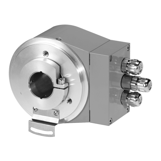
Installation and Addressing Installation and Addressing Mechanical structure Kabelverschraubung PG7 PG7 screwed cable bushing Klemmleiste 10 polig 10 terminals block Anschlußkasten (abnehmbar) Connection box (removable) DIL-Schalter DIL switch Blechfederelement für Sheet metal spring element for Ø6 Drehmomentstift Ø6 Ansicht X (von unten in View X (seen from the bottom, Anschaltkasten abgenommen) removed) -
Page 53: General Wiring Indications
Installation and Addressing General wiring indications: 2.2.1.1 Transmission cable features: The connection of the bus members among themselves onto the bus system is carried out using special field bus lines meeting the requirements of ISO 11898. The lines must show the following electrical characteristics. Parameter Unit Value... -
Page 54: Bus Connection
Installation and Addressing Bus connection Installation and settings Open the 4 hexagon socket head screws of the interface section to perform any setting or to connect the encoder to the CAN bus system and to the supply voltage The connecting section can then be removed and connected directly on site with the bus system and the supply voltage. - Page 55 Installation and Addressing 2.3.1.2 CAN Bus connection: 11 12 PIN Number Function PIN 1 Supply voltage +10..30 VDC PIN 2 Supply voltage GND Input CAN GND PIN 3 Input CAN LOW PIN 4 (CAN_L) • Input CAN HIGH PIN 5 (CAN_H) Output CAN HIGH (CAN_H) PIN 6...
-
Page 56: Bus Termination
Installation and Addressing 2.3.1.3 Supply voltage: The bus connecting part is visible after removing the connecting section and unscrewing the two screws of the printed circuit board. The +VDC and GND designation means that the supply voltage is looped internally. The corresponding connections are provided to that purpose on the printed circuit board. -
Page 57: Switch S2 Transmission Rate Setting
Installation and Addressing Hint: It is not necessary to connect any resistor externally. Switch S2-6 2.4.1.2 Bus termination enabled/disabled Switch S2-6 Switch S2 Value Status Bus termination Switch S2 Transmission rate setting The device supports 8 various transmission rates. The transmission rates meet the recommendation of the Communication Profile DS 301. - Page 58 Installation and Addressing 2.5.1.1 Transmission rate 10 KB Switch S2 Value Status Baud rate 10 Kb 2.5.1.2 Transmission rate 20 KB * Switch S2 Value Status Baud rate 20 Kb 2.5.1.3 Transmission rate 50 KB Switch S2 Value Status Baud rate 50 Kb 2.5.1.4 Transmission rate 125 KB (Factory default setting)
-
Page 59: Switch S1 Address Setting
Installation and Addressing 2.5.1.7 Transmission rate 1 MB Switch S2 Value Status Baud rate 1 Mb Switch S1 Address setting Switch S1[1-6] The node ID set is read and saved after applying the supply voltage, during the initialisation of the CAN encoder. The node ID may be set in the range between 0...63. - Page 60 Installation and Addressing Example: Address 35 Switch S1 Value Status Example: Address 63 (Default setting) Switch S1 Value Status Hint: Each node ID may only be assigned once! Node ID 0 is not allowed and will be set to 1 by the software.
-
Page 61: Can-Led Status
Diagnostics function 2.6.1 CAN-LED Status: red LED on Bus status ok Blinking Warning – Message could not be initiated off Bus off status green LED on Operational -Mode (see status diagram) off Pre-Operational Mode (see status diagram ) Diagnostics function 3.1.1.1 Switch S2-4 Diagnostics function If switch S2-4 is set to on and the power supply of the device is switched off... - Page 62 Diagnostics function 3.1.1.2 Diagnostics on/off Switch S2-4 Switch S2 Value Status Diagnostics Generally, a diagnostics object having the following meaning is sent every second on the bus: Diagnostics Message OBJECT 2016 Byte Status byte Value Description unsigned8 Subinde Description 00 ...FF Byte LSB Position 00 ...FF...
-
Page 63: Canopen Protocol
CANopen protocol CANopen protocol General 4.1.1.1 ISO/OSI Layer 1 and 2 The lower layers according to the OSI Model are defined by the standard ISO 11898. In addition, the standardisation for plug-in connectors and supported bit rates is given by Draft Standard CiA DS102-1. 4.1.1.2 Layer 7 (Protocol layer) For higher layers (layer 7), an organisation including several encoder... -
Page 64: Canopen Presettings
CANopen protocol Group Utility/Functionality Normal SDO free info lengths Emergency telegram Synch frame processing Event-driven PDO’s Synchronous PDO’s (synchronous timing) Standard PDO-Mapping according to Predefined Connection Set (optional) segmented Multiplex-Domain-Transfer DS 406 Device profile Full Class C2 integration Manufacturer- Diagnostics function specific Built-in LED for CAN Bus Status red Built-in LED for CAN Modes green... -
Page 65: Canopen Boot-Up Sequence
CANopen protocol The node address (Node ID) of the encoder can be modified using the DIL switches. This node ID may have values between 1..255, considering the fact that, using the „ Predefined Master-Slave Connection Set“ (according to CiA-DS-301), only values between 1..127 are defined. -
Page 66: Canopen Identifier Determination (Cob-Id) Communication Object
CANopen Identifier determination (COB-ID) Communication Object It is not necessary to use the „Prepared“ status with the Minimum Capability Device Boot-Up. CANopen Identifier determination (COB-ID) Communication Object 5.1.1.1 Determining the Identifier When using the Predefined Master/Slave Connection Set, the Information Identifiers are calculated as follows: The last 6 bits of the node-ID (01h...3Fh/01...63) are used as an offset on the Base Identifier. -
Page 67: Canopen Object Directory
CANopen Identifier determination (COB-ID) Communication Object CANopen Object directory The following table shows an overview of the supported Object Directory inputs defined by the Communication Profile CiA-DS-301. INDEX Object Attrib Name TYPE (hex) Symbol Name 1000 cons Device Type Unsigned32 1001 Error Register Unsigned8... -
Page 68: Can Open Object Directory Ds 406
CANopen Identifier determination (COB-ID) Communication Object 1A00 ARRAY 1st transmit PDO Mapping PDOMappin Par. 1A02 ARRAY 2nd transmit PDO Mapping PDOMappin Par. Index: The Index column describes the position of the input in the Object Directory Object: The Object column shows a pre-defined Object Name for the input Attribute: The Attribute column shows the access possibilities to the input rw = read and write... -
Page 69: Objects
CANopen Identifier determination (COB-ID) Communication Object 6509 Offset value (calculated) signed32 650A Manufacturer Offset value signed32 650B Serial Number unsigned32 Manufacturer Objects 3000 DOMAIN manufacturer module memory o Domain 3001 manufacturer memory unsigned16 location 3002 manufacturer memory size unsigned16 Index: The Index column describes the position of the input in the Object Directory Object:... - Page 70 CANopen Identifier determination (COB-ID) Communication Object Object 6000H Object Description Value Name Operating Parameters Object Code 7 (VAR) Data Type Index 6 (Unsigned16) Length Value Description Object Class C2 Mandatory Access PDO Mapping Value Range Unsigned16 Mandatory Range Default Value Structure of the parameters Function Bit = 0...
- Page 71 CANopen Identifier determination (COB-ID) Communication Object Object 6001H: Measuring units per revolution This parameter describes the number of different steps per revolution Object 6001H Object Description Value Main INDEX 6001H Name Meas. Units p.revolution Object Code 7 (VAR) Data Type Index 7 (Unsigned32) Length Value Description...
- Page 72 CANopen Identifier determination (COB-ID) Communication Object Object 6002H Object Description Value Subindex Description Total measuring range Value Range Unsigned32 Mandatory Range Object Function Object Class C2 Mandatory PDO mapping not possible Access Default Value Total measuring range in measuring units Byte 0 Byte 1 Byte 2...
- Page 73 CANopen Identifier determination (COB-ID) Communication Object to 2 to 2 to 2 to 2 Object 6004H: Position value This parameter describes the current position value. Object 6004H Object Description Value Main INDEX 6004H Name Position Value Object Code 7 (VAR) Data Type Index 7 (Unsigned32) Length...
- Page 74 CANopen Identifier determination (COB-ID) Communication Object Object 6200H Object Description Value Name Cyclic timer Object Code 7 (VAR) Data Type Index 6 (Unsigned16) Length Value Description Object Class C2 Mandatory Access PDO Mapping Value Range Unsigned16 Mandatory Range Default Value 0000 Important: This object is also used in Diagnostic Mode for the transmission rate of the diagnostic messages...
- Page 75 CANopen Identifier determination (COB-ID) Communication Object Function Bit = 0 Bit =1 Code Sequence Commissioning Diagnostic Not Supp. Supp. Control Scaling function control Disa. Enab. Reserved for further use Reserved for further use Reserved for further use Reserved for further use Reserved for further use Reserved for further use Reserved for further use...
- Page 76 CANopen Identifier determination (COB-ID) Communication Object Structure of the parameters SingleTurn resolution Byte 0 Byte 1 Byte 2 Byte 3 to 2 to 2 to 2 to 2 Object 6502H: Number of distinguishable revolutions (Multiturn) This parameter describes the number of revolutions that the encoder (multiturn) can emit.
- Page 77 CANopen Identifier determination (COB-ID) Communication Object Length Value Description Object Class C2 Mandatory Access PDO Mapping Value Range Unsigned16 Mandatory Range Default Value Structure of the parameters Function Bit = 0 Bit =1 Position error Commissioning diagnostics Error Reserved for further use Reserved for further use Reserved for further use Reserved for further use...
- Page 78 CANopen Identifier determination (COB-ID) Communication Object Value Description Object Class C2 Mandatory Access PDO Mapping Value Range Unsigned16 Mandatory Range Default Value Structure of the parameters Function Bit = 0 Bit =1 Position error Commissioning diagnostics Reserved for further use Reserved for further use Reserved for further use Reserved for further use...
- Page 79 CANopen Identifier determination (COB-ID) Communication Object Value Description Object Class C2 Mandatory Access PDO Mapping Value Range Unsigned16 Mandatory Range Default Value Structure of the parameters Function Bit = 0 Bit =1 Frequency exceeded Ligh control reserve Not reached Error CPU watchdog status Reset generated Operating time limit...
- Page 80 CANopen Identifier determination (COB-ID) Communication Object INDEX 6505H Name Supported Warnings Object Code 7 (VAR) Data Type Index 6 (Unsigned16) Length Value Description Object Class C2 Mandatory Access PDO Mapping Value Range Unsigned16 Mandatory Range Default Value Structure of the parameters Function Bit = 0 Bit =1...
- Page 81 CANopen Identifier determination (COB-ID) Communication Object Object 6507H: Profile Version This object shows the Profile Version implemented in the encoder in the first 16 bits. This is a combination of number and release. The second 16 bits indicate the software version and the index implemented in the encoder. Example: Profile version: 1.40 Binary code: 00000001 01000000...
- Page 82 CANopen Identifier determination (COB-ID) Communication Object Object 6508H: Operating Time This object contains the operating hours of the device. The value is saved in a non-volatile memory in the encoder. It shows the actual operating time in 0.1-hour steps. When this function is not in use, the value is set to FFFFFFFFh. Object 6508H Object Description Value...
- Page 83 CANopen Identifier determination (COB-ID) Communication Object Object 650AH: Module Identification Object 650Ah contains the „Module identification“ parameters: manufacturer offset value, manufacturer minimum position value, manufacturer maximum position value. The manufacturer offset value is saved in Sub-index 00h. This value shows information about the offset of the zero point in relation to the physical zero point of the encoder disk.
- Page 84 CANopen Identifier determination (COB-ID) Communication Object Object 650BH: Serial Number This object contains the serial number of the encoder. This is an unsigned 32-bits value. When the object is not in use, the manufacturer sets it to FFFFFFFFh. Object 650BH Object Description Value Main...
-
Page 85: Canopen Operating Modes
CANopen Operating Modes CANopen Operating Modes Event-Mode: event-driven operating mode the multiturn encoder continuously scans internally the current position and compares it with the previously sent position. If there is a deviation, the current position is emitted via the CAN Bus. The transmission is performed via a PDO Asynchronous Object. - Page 86 CANopen Operating Modes the transmission of the current position via the CAN bus synchronous timing-driven (Object 1006h + 1007h).the time set (Object 1006h) determines the synchronisation of the transmission The transmission is performed within a transmission window (Object 1007h) via a PDO Synchronous Object.
-
Page 87: Technical Features
Technical Features Technical Features Mechanical characteristics: Shape: round, with radial interface mounting surface External diameter: max. 90 m m Total length: max. 60 m m Hollow shaft diameter: Up to 28 m m Rotational speed: min. 1500 min (for IP 65) Protection according to IP65 EN60529:... -
Page 88: Abbreviations
Abbreviations Abbreviations CAN Application Layer. The Applications Layer for CAN-based networks, as they are defined in CiA Draft Standard 201..207. Controller Area Network. Data Link Layer Protocol for the serial communication defined in ISO 11898. CANopen consists of a profile family based on a communication section and various specific device sections. - Page 89 Fritz Kübler GmbH Zähl- und Sensortechnik Schubertstraße 47 78054 VS-Schwenningen GERMANY Phone +49 77 20 / 39 03-0 Fax +49 77 20 / 2 15 64 info@kuebler-gmbh.de www.kuebler-gmbh.de...
- Page 90 Manuel Codeurs multitours absolus Connexion par bus de terrain CANopen Exécution à arbre creux et sortant Type 9080...
- Page 91 Etude Sommaire ETUDE..................3 INSTALLATION ET ADRESSAGE..........4 ............4 TRUCTURE MECANIQUE : ........5 NDICATIONS GENERALES DE CABLAGE ............6 ACCORDEMENT AU BUS ..............8 ERMINAISON DU BUS S2 R ..9 OMMUTATEUR EGLAGE DE LA VITESSE DE TRANSMISSION S1 R ’ ....... 11 OMMUTATEUR EGLAGE DE L ADRESSE 2.6.1 LED d’état CAN :..............
-
Page 92: Etude
Etude Etude Le chapitre Etude contient les informations nécessaires pour le développement de systèmes de commande utilisant les codeurs absolus 9080. Ces informations vont des indications sur les exécutions disponibles jusqu’à l’extension maximale d’un système utilisant une ligne bus CAN. ©... -
Page 93: Installation Et Adressage
Installation et adressage Installation et adressage Structure mécanique Kabelverschraubung PG7 Passe-câble à vis PG7 Klemmleiste 10 polig Bornier à 10 bornes Anschlußkasten (abnehmbar) Boîtier de connexion (amovible) DIL-Schalter Commutateur DIL Blechfederelement für Elément ressort en tôle pour goupille Drehmomentstift Ø6 Ø6 Ansicht X (von unten in Vue selon X (vue du dessous du... -
Page 94: Indications Generales De Cablage
Installation et adressage Indications générales de câblage : 2.2.1.1 Caractéristiques du câble de transmission : La liaison des participants au système bus entre eux est réalisée à l’aide de lignes spéciales de bus de terrain suivant la norme ISO 11898. Les lignes doivent présenter les caractéristiques suivantes. -
Page 95: Raccordement Au Bus
Installation et adressage Raccordement au bus Installation et réglages Pour tous les réglages, et pour le raccordement du codeur au système bus CAN et à la tension d’alimentation, il faut retirer les 4 vis CHc de la partie interface. Il est alors possible de retirer la partie raccordement et de la relier directement, sur place, au système bus et à... - Page 96 Installation et adressage 2.3.1.2 Raccordement au bus CAN : Broche 11 12 N° de broche Fonction BROCHE 1 Tension d’alimentation +10..30 VDC BROCHE 2 Tension d’alimentation GND Entrée CAN GND BROCHE 3 Entrée CAN LOW BROCHE 4 (CAN_L) • Entrée CAN HIGH BROCHE 5 (CAN_H) Sortie CAN HIGH (CAN_H)
-
Page 97: Terminaison Du Bus
Installation et adressage 2.3.1.3 Tension d’alimentation : L’élément de raccordement au bus apparaît après avoir démonté la partie raccordement et retiré les deux vis du circuit imprimé. Les indications +VDC et GND signifient que la tension d’alimentation e st également bouclée en interne. -
Page 98: Commutateur S2 Reglage De La Vitesse De Transmission
Installation et adressage Remarque : il n’est pas nécessaire de brancher une résistance en externe. Commutateur S2-6 2.4.1.2 Terminaison de bus activée/désactivée Commutateur S2-6 Commutateur S2 Valeur Etat Terminaison de bus activée désactivée Commutateur S2 Réglage de la vitesse de transmission Le système supporte 8 vitesses de transmission différentes. - Page 99 Installation et adressage 2.5.1.1 Vitesse de transmission 10 KB Commutateur S2 Valeur Etat Bauds 10 Kb 2.5.1.2 Vitesse de transmission 20 KB * Commutateur S2 Valeur Etat Bauds 20 Kb 2.5.1.3 Vitesse de transmission 50 KB Commutateur S2 Valeur Etat Bauds 50 Kb 2.5.1.4...
-
Page 100: Commutateur S1 Reglage De L
Installation et adressage 2.5.1.7 Vitesse de transmission 1 MB Commutateur S2 Valeur Etat Bauds 1 Mb Commutateur S1 Réglage de l’adresse Commutateur S1[1-6] L’identificateur nodal réglé est lu et enregistré après la mise sous tension, pendant l’initialisation du codeur CAN. L’ID nodal peut se régler dans la plage 0...63, sous la forme d’une valeur binaire. - Page 101 Installation et adressage Exemple : Adresse 35 Commutateur S1 Valeur Etat Exemple : Adresse 63 (Réglage par défaut) Commutateur S1 Valeur Etat Remarque : Chaque ID nodal ne peut être attribué qu’une seule fois ! L’ID nodal 0 n’est pas admis : il est mis à 1 par le logiciel. Page 12 ©...
-
Page 102: Led D'état Can
Fonction diagnostic 2.6.1 LED d’état CAN : LED rouge allumée Etat du bus ok clignotante Avertissement – impossible d’initier le message éteinte Etat du bus off LED verte allumée Mode opérationnel (voir diagramme des états) éteinte Mode préopérationnel (voir diagramme des états ) Fonction diagnostic 3.1.1.1 Commutateur S2-4 Fonction diagnostic... - Page 103 Fonction diagnostic 3.1.1.2 Diagnostic activé/désactivé Commutateur S2-4 Commutateur S2 Valeur Etat Diagnostic actif inactif En général, un objet diagnostic ayant la signification suivante est émis chaque seconde sur le bus : Message Diagnostic OBJET 2016 Octet Octet d’état Valeur Description unsigned8 Subinde Description...
-
Page 104: Protocole Canopen
Protocole CANopen Protocole CANopen Généralités 4.1.1.1 Niveaux ISO/OSI 1 et 2 Selon le modèle OSI, les niveaux inférieurs sont définis par la norme ISO 11898. Le projet de norme CiA DS102-1 fait appel, en complément, aux normes pour les connecteurs à fiches et les débits binaires supportés. 4.1.1.2 Niveau 7 (Niveau de protocole) Un profil d’appareil a été... -
Page 105: Prereglages Can Open
Protocole CANopen Groupe Utilité/Fonctionnalité Via SDO pendant l’état PREOPERATIONNEL Fonctionnalité Expedited-SDO, max. 4 (Bytes) Transfert de CANopen données SDO Normal, longueur des infos libre Télégramme d’urgence Exploitation Synch-Frame Event-Driven PDO’s (commandés par événement) Synchron-PDO’s (synchrones) PDO-Mapping Standard selon le Predefined Connection Set (option) Transfert de domaine multiplex segmenté... -
Page 106: Sequence De Lancement De Can Open
Protocole CANopen temporisation de 20 ms afin de donner au codeur le temps de modifier son état interne. 4.3.1.4 Réglage de l’adresse nodale Les commutateurs DIL permettent de modifier l’adresse nodale (ID nodal) du codeur. Cet ID nodal peut avoir des valeurs entre 1..255, en tenant compte du fait que seules des valeurs entre 1..127 sont définies dans le «... -
Page 107: Determination De L'identifiant Canopen (Cob-Id) Objet De Communication
Détermination de l’identifiant CANopen (COB-ID) Objet de communication Enter-Pre-Operational (Passage dans le mode Préopérationnel) Reset Node (Réinitialisation du nœud Can) Reset Communication (Réinitialisation de la communication) Init finished (Initialisation terminée, passage auto après Préopérationnel) L’état « Préparé » ne doit pas nécessairement être utilisé dans le cas du lancement Minimum-Capability-Device. -
Page 108: Liste Des Objets Canopen
Détermination de l’identifiant CANopen (COB-ID) Objet de communication (identifiant de base) – 1 + (Offset) Valeur de position asynchrone (ID nodal réglé à 05h) 385 – 1 + 5 = 389 -> 185h identifiant déterminé SDO Lire Objet (ID nodal réglé à 63h) 1409 –... -
Page 109: Liste Des Objets
Détermination de l’identifiant CANopen (COB-ID) Objet de communication 1400 RECORD 1st receive PDO Comm. Par. PDOComPar 1402 RECORD 2nd receive PDO Comm. Par. PDOComPar 1600 ARRAY 1st receive PDO Mapping Par. O PDOMappin 1602 ARRAY 2nd receive PDO Mapping PDOMappin Par. -
Page 110: Liste Des Objets
Détermination de l’identifiant CANopen (COB-ID) Objet de communication 6100 Transmission Rate unsigned16 6101 Node Number unsigned16 6200 Cyclic Timer unsigned16 Diagnostics 6500 Operating Status unsigned16 6501 Measuring Step unsigned32 6502 Number of revolutions unsigned16 6503 Alarms unsigned16 6504 Supported alarms unsigned16 6505 Warnings... -
Page 111: Objets
Détermination de l’identifiant CANopen (COB-ID) Objet de communication Liste des objets CANopen DS 406 5.4.1 Objets Objet 6000H : Operating Parameters (paramètres de fonctionnement) Code Sequence (Séquence de code) : La séquence de code détermine si la valeur de la position augmente ou diminue pour une rotation de l’arbre du codeur dans le sens horaire (CW) ou anti-horaire (CCW). - Page 112 Détermination de l’identifiant CANopen (COB-ID) Objet de communication Structure des paramètres Fonction Bit = 0 Bit =1 Code Sequence Commissioning Diagnostic Disa. Enab. Control Scaling function control Disa. Enab. Reserved for further use Reserved for further use Reserved for further use Reserved for further use Reserved for further use Reserved for further use...
- Page 113 Détermination de l’identifiant CANopen (COB-ID) Objet de communication Objet 6001H : Measuring units per revolution (Unités de mesure par tour) Ce paramètre indique le nombre de pas par tour Objet 6001H Description Valeur Main INDEX 6001H Name Meas. Units p.revolution Object Code 7 (VAR) Data Type Index...
- Page 114 Détermination de l’identifiant CANopen (COB-ID) Objet de communication Objet 6002H Description Valeur Value Description Subindex Description Total measuring range Value Range Unsigned32 Mandatory Range Object Function Object Class C2 Mandatory PDO mapping not possible Access Default Value Plage de mesure totale en unités de mesure Byte 0 Byte 1 Byte 2...
- Page 115 Détermination de l’identifiant CANopen (COB-ID) Objet de communication Default Value Valeur de présélection Byte 0 Byte 1 Byte 2 Byte 3 à 2 à 2 à 2 à 2 Objet 6004H : Position value (Valeur de la position) Ce paramètre indique la valeur de la position courante. Objet 6004H Description Valeur...
- Page 116 Détermination de l’identifiant CANopen (COB-ID) Objet de communication Objet 6200H : Cyclic Timer (Horloge cyclique) L’objet 6200h décrit le paramètre « Cyclic timer » (Horloge cyclique). L’horloge cyclique définit l’intervalle de temps pour tous les PDO asynchrones (p. ex PDO 1800h). La transmission cyclique de la valeur de la position est activée lorsque la valeur de l’horloge est programmée >...
- Page 117 Détermination de l’identifiant CANopen (COB-ID) Objet de communication Name Operating status Object Code 7 (VAR) Data Type Index 6 (Unsigned16) Length Value Description Object Class C2 Mandatory Access PDO Mapping Value Range Unsigned16 Mandatory Range Default Value Structure des paramètres Fonction Bit = 0 Bit =1...
- Page 118 Détermination de l’identifiant CANopen (COB-ID) Objet de communication Objet 6501H : Single Turn resolution (rotary) (Résolution monotour (rotatif)) Ce paramètre indique la résolution du codeur (monotour) La valeur maximum est de 2 Objet 6501H Description Valeur Main INDEX 6501H Name Single Turn resolution (M.S) Object Code...
- Page 119 Détermination de l’identifiant CANopen (COB-ID) Objet de communication Data Type Index 6 (Unsigned16) Length Value Description Object Class C2 Mandatory Access PDO Mapping Value Range Unsigned16 Mandatory Range Default Value Objet 6503H : Alarms (Alarmes) En plus des télégrammes d’urgence, cet objet signale d’autres états d’alarme.
- Page 120 Détermination de l’identifiant CANopen (COB-ID) Objet de communication Structure des paramètres Fonction Bit = 0 Bit =1 Position error Commissioning diagnostics Error Reserved for further use Reserved for further use Reserved for further use Reserved for further use Reserved for further use Reserved for further use Reserved for further use Reserved for further use...
- Page 121 Détermination de l’identifiant CANopen (COB-ID) Objet de communication Structure des paramètres Fonction Bit = 0 Bit =1 Position error Commissioning diagnostics Reserved for further use Reserved for further use Reserved for further use Reserved for further use Reserved for further use Reserved for further use Reserved for further use Reserved for further use...
- Page 122 Détermination de l’identifiant CANopen (COB-ID) Objet de communication Default Value Structure des paramètres Fonction Bit = 0 Bit =1 Frequency exceeded Ligh control reserve Not reached Error CPU watchdog status Reset generated Operating time limit warning Battery charge Too low Reference point Reached Not reached...
- Page 123 Détermination de l’identifiant CANopen (COB-ID) Objet de communication Value Description Object Class C2 Mandatory Access PDO Mapping Value Range Unsigned16 Mandatory Range Default Value Structure des paramètres Fonction Bit = 0 Bit =1 Frequency exceeded Supporte supported Ligh control reserve Supporte supported CPU watchdog status...
- Page 124 Détermination de l’identifiant CANopen (COB-ID) Objet de communication Objet 6507H : Profile Version (Version de profil) Cet objet indique, dans les 16 premiers bits, la version du profil implémenté dans le codeur. Il s’agit d’une combinaison du numéro et de l’indice de modification.
- Page 125 Détermination de l’identifiant CANopen (COB-ID) Objet de communication Objet 6508H : Operating Time (Temps de fonctionnement) Cet objet contient les heures de fonctionnement de l’appareil. Cette valeur est enregistrée dans une mémoire non-volatile du codeur ; elle indique le temps réel de fonctionnement en 1/10 d’heures. Si cette fonction n’est pas utilisée, la valeur est mise à...
- Page 126 Détermination de l’identifiant CANopen (COB-ID) Objet de communication Objet 6509H : Offset Value (Valeur du décalage) Cet objet contient le décalage entre la valeur courante de la position du codeur et la valeur préréglée (Preset value). Objet 6509H Description Valeur Main INDEX 6509H...
- Page 127 Détermination de l’identifiant CANopen (COB-ID) Objet de communication Access PDO Mapping Value Range Signed32 Mandatory Range Default Value Sub-Index Description manufacturer_min_position_value Object Class optional Access PDO Mapping Value Range Signed32 Mandatory Range Default Value Sub-Index Description manufacturer_max_position_value Object Class optional Access PDO Mapping Value Range...
- Page 128 Détermination de l’identifiant CANopen (COB-ID) Objet de communication Access PDO Mapping Value Range Unsigned32 Mandatory Range Default Value © Fritz Kübler GmbH, Zähl-und Sensortechnik Page 39...
-
Page 129: Modes Operatoires Canopen
Modes opératoires CANopen Modes opératoires CANopen Event-Modus : mode opératoire commandé par les événements Le codeur multitours lit continuellement la position courante et la compare à la dernière position émise. Dans le cas d’une déviation, la nouvelle position est émise par l’intermédiaire du bus CAN. L’émission s’effectue à... - Page 130 Modes opératoires CANopen L’émission de la position courante sur le bus CAN est commandée de manière synchrone (objet 1006h + 1007h). Le temps réglé (objet 1006h) détermine la synchronisation de l’émission. L’émission s’effectue à l’intérieur d’une fenêtre de transmission (objet 1007h) sous la forme d’un objet synchrone PDO.
-
Page 131: Caracteristiques Techniques
Caractéristiques techniques Caractéristiques techniques Caractéristiques mécaniques : Forme extérieure : rond, avec surface radiale pour montage de l’interface Diamètre extérieur : max. 90 m m Longueur totale : max. 60 m m Diamètre de l’arbre creux : jusqu’à 28 m m Vitesse de rotation : 1500 tours/min (pour IP 65) Indice de protection selon... -
Page 132: Abreviations
Abréviations Abréviations Niveau d’application CAN. Le niveau des applications pour les réseaux basés sur CAN, comme ils sont définis dans le projet de norme CiA 201..207. Controller Area Network. Protocole Data Link Layer pour la communication série défini dans ISO 11898. CANopen se compose d’une famille de profils basée sur une partie communication et plusieurs parties appareil spécifiques. - Page 133 Fritz Kübler GmbH Zähl- und Sensortechnik Schubertstraße 47 78054 VS-Schwenningen GERMANY Tél. +49 77 20 / 39 03-0 Fax +49 77 20 / 2 15 64 info@kuebler-gmbh.de www.kuebler-gmbh.de...
Need help?
Do you have a question about the 9080 Series and is the answer not in the manual?
Questions and answers