Table of Contents
Advertisement
O P E R AT I N G ,
M A I N T E N A N C E
& PA R T S
M A N U A L
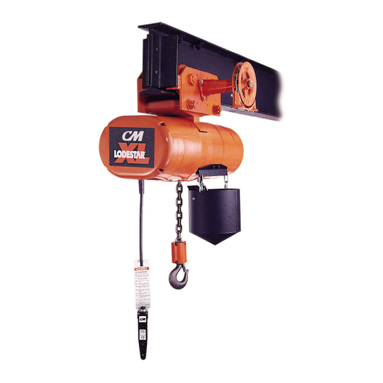
E L E C T R I C
C H A I N H O I S T
52756
®
Before installing hoist, fill in
the information below. Refer
to the hoist identification
plate.
Model No. __________________
Serial No. __________________
Purchase Date ______________
Voltage ____________________
Rated Capacity______________
Rated capacities 2 through 7½ tons/
2000 through 7500 kg
Follow all instructions and warnings for
inspecting, maintaining and operating this hoist.
The use of any hoist presents some risk of personal
injury or property damage. That risk is greatly
increased if proper instructions and warnings are not
followed. Before using this hoist, each operator
should become thoroughly familiar with all warnings,
instructions and recommendations in this manual.
Retain this manual for future reference and use.
Forward this manual to operator.
Failure to operate equipment as directed
in manual may cause injury.
X X L L
Manual No. 652-E
Advertisement
Table of Contents

Related Manuals for CM Lodestar XL


Summary of Contents for CM Lodestar XL
- Page 1 O P E R AT I N G , M A I N T E N A N C E & PA R T S M A N U A L E L E C T R I C C H A I N H O I S T X X L L ®...
- Page 2 XL HOIST PARTS AND SERVICES ARE AVAILABLE IN THE UNITED STATES AND IN CANADA ® As a CM XL Hoist user, you are assured of reliable repair and parts services through a network of Master Parts Depots and Service Centers that are strategically located in the United States and Canada. These facilities have been selected on the basis of their demonstrated ability to handle all parts and repair requirements promptly and efficiently.
-
Page 3: Safety Precautions
® Each CM Lodestar XL Electric Hoist is built in accordance with the specifications contained herein and at the time of manufacture complied with our interpretation of applicable sections of the *American Society of Mechanical Engineers Standard B30.16 “Overhead Hoists,” the National Electrical Code (ANSI/NFPA 70) and the Occupational Safety and Health Act. -
Page 5: Table Of Contents
FOREWORD This manual contains important information to help you properly install, operate and maintain your hoist for maxi- mum performance, economy and safety. Please study its contents thoroughly before putting your hoist into operation. By practicing correct operating proce- dures and by carrying out the recommended preventative maintenance suggestions, you will experience long, depend- able and safe service. -
Page 6: General Information
GENERAL INFORMATION SPECIFICATIONS • Oversize reversing and speed selecting contactors The CM LODESTAR XL Electric Chain Hoist is a highly ® for long, trouble free service. versatile material handling device that can be used to • Hoist duty, A.C. motor brake plus regenerative braking. -
Page 7: Repair/Replacement Policy
These are manual push type trolleys designed for use with Limitations of Warranties, Remedies and Damages, and the LODESTAR XL Electric Hoist. The trolley is adjustable to Indemnification and Safe Operation. operate on a range of American Standard ‘S’ beams and flat flanged beams. -
Page 8: Unpacking
INSTALLATION UNPACKING After opening the carton, carefully inspect the hoist, suspension, trolley and chain container for damage that may have occurred during shipment. If there is damage, refer to the packing slip envelope. INSPECT FOR SHIPPING DAMAGE MOTOR DRIVEN TROLLEY CHAIN CONTAINER This accessory is used to hold the slack chain and it is supplied complete with mounting hardware and... - Page 9 c. After the hook is in the desired position, slide the suspension adapter into cavity on top of hoist and secure it using the suspension adapter screw from the kit. Tighten screw to a seating torque of 16 pound feet (22 NM). COUNTERWEIGHT INSTALLING HOOK...
-
Page 10: Lug Suspensions
2. 3, 4 And 5 Ton Double Reeved And 5, 6 And 7½ Ton Triple Reeved Units. Slide the suspension adapter into cavity on top of hoist. Install dead end bolt and thread it by hand to engage the dead end CHANGING block (3, 4 and 5 ton double reeved units) or idler POSITION OF... -
Page 11: Installing Trolley Suspended Hoist On Beam
3. For 2 ton units, assemble a slotted nut to one end of each suspension bolt and secure it using a cotter pin. Spread legs of cotter pin to keep it in place. Using Table 2 as a reference for washer spacing, assemble side frames and bolts and washers together as shown below. -
Page 12: Installing Breather
Before installing geared or motor driven trolleys (2 ton POWER SUPPLY SYSTEM only) on the beam, lubricate the trackwheel gears and To insure proper operation, to avoid damage to pinion with Texaco Novatex #2 or equivalent heavy cup hoist and electrical system and to reduce the risk of grease. -
Page 13: Electrical Connections
WARNING 3. Reassemble motor cover (and counterweight if so equipped) to hoist frame. Failure to provide a proper power supply system for the hoist may cause hoist damage and offers the 4. Mark the tag attached to power cord to indicate potential for a fire. -
Page 14: Checking For Twist In Load Chain
NOMINAL MINIMUM * MIN. VOLTAGE 3. Move the manual disconnect switch handle to the POWER OPERATING AT INSTANT “ON” position. SUPPLY VOLTAGE OF START 4. Depress the (up) control. If the hook moves in the up direction, the hoist is ready for operation. If the 208-3-60 hook lowers, move the disconnect switch handle to 220-3-50... -
Page 15: Operating Instructions
4. If material being handled must be immersed in WARNING water, pickling baths, any liquid, dusty or loose solids, use a sling chain of ample length so that the Tying knots or loops to shorten the drop of the control sta- hook is always above the surface. -
Page 16: Inspections
The type of service to which the hoist is subjected can be 4. Do not use this or any other overhead materials han- classified as “Normal,” “Heavy,” or “Severe.” dling equipment for lifting persons. Normal Service: Involves operation with randomly distrib- uted loads within rated load limit, or uniform loads less 5. -
Page 17: Load Chain
LOAD CHAIN LATCH TYPE HOOK (Upper and Lower) Cleaning and Inspection TO MEASURE OPENING, First clean load chain with a non-acid or non-caustic type DEPRESS LATCH AGAINST solvent. Then slack the chain and make a link-by-link HOOK BODY AS SHOWN. inspection for nicks, gouges, twisted links and excessive wear or stretching. - Page 18 Table 3. Minimum Frequent Inspections TYPE OF SERVICE ITEM Severe Normal Heavy Brake for evidence of slippage. Control functions for proper operation. Hooks for damage, cracks, twists, excessive throat opening. latch engagement and latch operation–see page 13. Load chain for adequate lubrication, as well as for signs of wear, damaged links or foreign matter–see page 15.
-
Page 19: Hoist
Bearings. All bearings except the lower hook thrust LUBRICATION bearings are pre-lubricated or are in an oil bath and need no lubrication. The lower hook thrust bearing WARNING should be lubricated at least once a month with heavy duty machine oil. The lubricants used in and recommended for the XL Hoist Miscellaneous. -
Page 20: Limit Switches
LIMIT SWITCHES If limit switch operation has been checked as described on page 10 and is not operating correctly or is not auto- matically stopping the hook at a desired position, pro- ceed as follows: 1. Disconnect hoist from power supply. 2. -
Page 21: Trolley Brake
TROLLEY BRAKE (2 TON UNIT) (Optional Accessory) The stopping distance of the Motor Driven Trolley equipped with an electric brake can be increased or decreased by adjusting the brake pressure. To increase brake pressure, and thereby decrease stopping distance, move the brake spacer washers progressively from the nut side of the brake field plate to the spring side. -
Page 22: Recommended Spare Parts
Replacement of Coil RECOMMENDED SPARE PARTS (Refer to Figure 1 on page 17 and Exploded To insure continued service of the XL Hoist, the following is a list of parts that are recommended View Drawing on page 48). to be kept on hand at all times to replace parts that have worn or failed. -
Page 23: Trouble Shooting
TROUBLE SHOOTING TROUBLE PROBABLE CAUSE CHECK AND REMEDY ALL HOISTS Hook does not A) No voltage at hoist—mainline or A) Close switch, replace fuse or branch circuit switch open; branch reset breaker. respond to the line fuse blown or circuit breaker control station. - Page 24 TROUBLE PROBABLE CAUSE CHECK AND REMEDY A) Check connections with the A) Wiring connections reversed at 2. Hook moves in the wiring diagram. either the control station or wrong direction. terminal board. B) Phase reversal. B) Refer to installation instructions on page 9 (all hoists).
- Page 25 TROUBLE PROBABLE CAUSE CHECK AND REMEDY A) See Item 1H. A) Excessive Load. 8. Motor overheats. B) Check for low voltage condition B) Low Voltage. as described on page 10. C) Above an ambient temperature C) Extreme external heating. of 104°F. (40°C.), the frequency of hoist operation must be lim- ited to avoid overheating of motor.
-
Page 26: Two Speed Hoists
TROUBLE PROBABLE CAUSE CHECK AND REMEDY TWO SPEED HOISTS A) Open or shorted motor wind- 11. Hoist will not oper- A) Open Circuit. ing, loose or broken wire in ate at slow speed in circuit, speed selecting contac- either direction. tor stuck in opposite speed mode. -
Page 27: Motor Driven Trolley
TROUBLE PROBABLE CAUSE CHECK AND REMEDY MOTOR DRIVEN TROLLEY 18) Trolley does not A) No voltage at motor. A) Open circuit, grounded or faulty operate in either connection in hoist wiring. direction. B) Phase failure. B) See Item 1B. C) Open control circuit. C) See Item 1D. -
Page 28: Electrical Data
ELECTRICAL DATA TO DETECT OPEN AND SHORT CIRCUITS IN ELECTRICAL COMPONENTS Open circuits in the coils of electrical components may resistance substantially below normal. The current be detected by isolating the coil and checking for conti- method is recommended for coils with very low D.C. nuity with an ohmmeter or with the unit in series with a resistance. - Page 29 HOIST MOTORS (652-162) *D.C. RESISTANCE (OHMS)-LEADS CURRENT (AMPS) VOLTS-PHASE H.P. 11-12 STARTING FULL LOAD 11-13 -HERTZ (KW) 12-13 230/460-3-60 3.5 (2.7) – – 18.4/6.4 11.5/5.8 220/380-3-50 3.5 (2.7) 13.6/6.4 11.9/5.9 – – 13.6/6.4 11.9/5.8 220/415-3-50 3.5 (2.7) – – 230/460-3-60 5.7 (4.3) 23.2/8.0 14.5/7.3...
-
Page 30: Wiring Diagrams
TYPICAL WIRING DIAGRAMS Wiring diagrams shown are representative. Consult wiring diagram in hoist or furnished with unit. SINGLE SPEED - HOIST ONLY 2 TON - SINGLE SPEED HOIST WITH TROLLEY... - Page 31 TWO SPEED - HOIST ONLY 2 TON - TWO SPEED HOIST WITH TROLLEY...
- Page 32 3-7½ TON - SINGLE SPEED HOIST WITH TROLLEY 3-7½ TON 2 SPEED HOIST WITH SINGLE SPEED TROLLEY...
-
Page 33: Disassembly
DISASSEMBLY 14. Remove the chain stripper (652-114) and chain guide (652-113). Refer to pages 30 through 40 for exploded view and 15. On the 3, 4, and 5 ton (Double Reeved) units, parts list. The following are general guide lines for dis- assembling the XL Hoist. -
Page 34: Reeving Load Chain
on the liftwheel, it will not be possible to install the METHOD 1 chain guide. After making sure the chain is correctly Disconnect the hoist from the power supply system. installed on the liftwheel, continue to assemble the Remove the motor end cover (652-182). On units hoist. -
Page 35: 5, 6 And 7 1/2 Ton Triple Reeved Units
REEVING LOAD CHAIN REEVING LOAD CHAIN 3,4 AND 5 TON HOISTS 5,6 AND 7 1/2 TON HOISTS HOOK SUSPENSION SHOWN. LUG SUSPENSION SIMILAR HOOK SUSPENSION SHOWN LUG SUSPENSION SIMILAR Hoistaloy load chain is hardened and it is difficult to CUTTING CHAINS 5, 6 AND 7 1/2 TON TRIPLE REEVED UNITS cut. -
Page 36: Testing
NOTE: WHEN ORDERING REPLACEMENT PARTS, IT IS WARNING RECOMMENDED THAT CONSIDERATION BE Cutting Chain Can Produce Flying Particles. GIVEN TO THE NEED FOR ALSO ORDERING SUCH ITEMS AS GASKETS, FASTENERS, INSU- TO AVOID INJURY: LATORS, SEALS, ETC. THESE ITEMS MAY BE •... -
Page 37: Exploded Views And Parts Lists
XL Electric Chain Hoist Parts List KEY NO. NO. REQ’D PART NAME PART NUMBER KEY NO. NO. REQ’D PART NAME PART NUMBER 652-100 BRAKE HUB SNAP RING 35764 652-135 208-240/380-480 VOLT 68811 652-101 2ND GEAR SNAP RING 36763 PRIMARY, 24 VOLT SECONDARY 652-102 2ND PINION SNAP RING 45766... - Page 38 52028C 6 AND 2/6 52613 652-182 MOTOR END COVER 52031C 8 AND 2.7/8 52614 652-183 IDENTIFICATION PLATE: 52626 LODESTAR XL 70728 7 1/2 6 AND 2/6 52665 652-184 BRAKE END COVER SCREW 80409 7 1/2 52661 652-161 ELECTRIC BRAKE COMPLETE: 652-185 I.D.
- Page 39 When ordering lubricants, specify the type of lubricant, part number and packaged quantity required. Touch-up Paints for Lodestar XL Electric Chain Hoists and 2 Ton Trolley Order: (1) case (12-12 oz. Aerosol Cans) of Orange Touch-up paint Part Number 84190.
- Page 40 3 THRU 7½ TON MOTOR AND GEAR BOX ASSEMBLY TROLLEY BRAKE (OPTIONAL) *SEE PAGE 47 FOR TROLLEY BRAKE ASSEMBLY REF. PART NUMBER PART DESCRIPTION NO. REQ’D 3-7 1/2 TON MOTOR & GEARBOX ASS’Y (LESS POWER CORD) BET-3000 MOTOR (INCLUDES REF. NO.2 BET-3001 MOTOR KEY (3/16 X 3/16 X 1 1/4”) BET-3002...
- Page 41 *SEE ALSO 652-219 COUNTER WEIGHT IF ORDERING HOOK SUS- PENSION PARTS SEPARATELY. •For control station and control sta- tion parts see pages 45 and 46...
- Page 42 ANTI-TIPPING BRACKET KIT 670-464 2 TON...
- Page 43 FOR USE WITH ANTI-TIPPING ROLLER 652-301 HOIST SUSPENSION ADAPTER 52059 MOTOR DRIVEN 652-302 SUSPENSION ADAPTER SCREW / DEAD END BOLT 987208 TROLLEYS 652-303 “CM” LABEL 25779 670-321 HANDWHEEL BRACKET WITH BUSHINGS 59616 670-304 SUSPENSION BOLT FOR : 670-322 HANDWHEEL BUSHING 58727 3.25”...
- Page 44 KEY NO. NO. REQ’D PART NAME PART NUMBER KEY NO. NO. REQ’D PART NAME PART NUMBER 2 TON 2 TON 670-347 MOTOR PINION FOR : 670-378 POWER CORD CONNECTOR 89926 35 AND 65 FPM TROLLEYS (10.7 and 19.8 MPM) 54356 670-380 TERMINAL BOX GASKET 59991...
- Page 46 PART NUMBER 3 TON 4-7 1/2 TON REF. PART DESCRIPTION REQ’D PLAIN GEARED MOTOR PLAIN GEARED MOTOR DRIVEN DRIVEN SIDE PLATE ASSEMBLY FOR: 4” TO 61/4” FLG. AND PATENTED TRACK 700T-1400 700T-1700 BET-2800 700T-1501 700T-1801 BET-3801 6 3/8” TO 8 ”...
- Page 47 Single Speed Hoist Control Station Key No. Part Name Qty. Code 627-250 Standard Control Cord Assembly See page 35 627-551 Control Station Grommet 58278 627-552 Control Station (Includes 627-551 thru 627-567) 58272 627-563 Control Station Hardware Kit w/gasket 58275 627-565 Control Station 1-speed Insert 58255 627-566...
- Page 48 Two Speed Hoist Control Station Key No. Part Name Qty. Code 627-250 Standard Control Cord Assembly See Page 35 627-551 Control Station Grommet 58278 627-552 Control Station (Included 627-551 Thru 627-567) 58273 627-563 Control Station Hardware Kit w/gasket 58275 627-565 Control Station 2-speed Insert 58256 627-566...
- Page 49 Standard Control Cord Assembly See Page 35 627-551 Control Station Grommet 58278 635-156 Control Station (Includes 627-551 Thru 627-567) 58220 CM Control Station Housing Kit (Includes Housing, Boots, 627-553 58288 Collar, Gasket & Hardware) 627-563 Control Station Hardware Kit w/gasket...
- Page 50 3 THRU 7½ TON TROLLEY MOTOR BRAKE EXPLODED VIEW Key No. No. Req’d Part Name Part Number Brake Cord 51074 Coupler Brake Shaft KIt (includes Shaft, Bearing,Snap Ring, Retainer Ring and Key) Housing Mounting Stud with Nut Access Cover -Plain Access Cover Screw (Specify No.
- Page 51 NOTES...
- Page 52 Note: When ordering parts, always furnish Hoist Model and Serial Number, Motor Horsepower, Voltage, Phase, Frequency and Rated Capacity of hoist on which the parts are to be used. For the location of the nearest Master Parts Depot, see the list located on the inside front cover.
Need help?
Do you have a question about the Lodestar XL and is the answer not in the manual?
Questions and answers
what type oil is used in the gear box
For 3 to 7½ ton trolleys of the CM Lodestar XL, the gearbox uses Mobil SHC-626 or an equivalent oil. For 2 ton trolleys, refill with one gallon (3.86 liters) of gear oil, such as Texaco Novatex No. 1 or Amoco 85W-140, or an equivalent medium cup grease.
This answer is automatically generated