Table of Contents
Advertisement
Quick Links
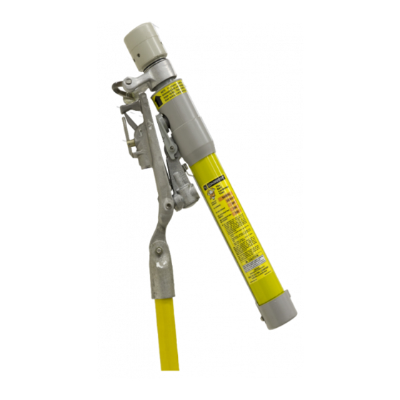
Loadbuster
®
-The S&C Loadbreak Tool
Outdoor Distribution (14.4 kV, 27 kV, and 34.5 kV)
Table of Contents
Section
Qualified Persons . . . . . . . . . . . . . . . . . . . . . . . . . . . . . . 2
Read this Instruction Sheet . . . . . . . . . . . . . . . . . . . . . . . 2
Retain this Instruction Sheet . . . . . . . . . . . . . . . . . . . . . . 2
Video . . . . . . . . . . . . . . . . . . . . . . . . . . . . . . . . . . . . . . . . 2
Proper Application . . . . . . . . . . . . . . . . . . . . . . . . . . . . . . 2
Warranty . . . . . . . . . . . . . . . . . . . . . . . . . . . . . . . . . . . . . 2
Understanding Safety Alert Messages . . . . . . . . . . . . . . 3
Following Safety Instructions . . . . . . . . . . . . . . . . . . . . . 3
Replacement Labels and Instructions . . . . . . . . . . . . . . . 3
Location of Safety Labels . . . . . . . . . . . . . . . . . . . . . . . . 4
December 5, 2016
©
S&C Electric Company 2016, all rights reserved
Inspection and Maintenance
Page
Section
. . . . . . . . . . . . . . . . . . . . . . . . . . . . . . . . 5
. . . . . . . . . . . . . . . . . . . . . . . . . . . . . . 6
. . . . . . . . . . . . . . . . . . . . . . . . . . . . . 16
Table of Replacement Parts . . . . . . . . . . . . . . . . . . . . . 24
Enhanced Operating Life Upgrade Kits . . . . . . . . . . . . 26
Instruction Sheet 811-510
Page
. . . . . . . . . . . . . . 12
Advertisement
Table of Contents

Related Manuals for S&C Loadbuster

Summary of Contents for S&C Loadbuster
-
Page 1: Table Of Contents
Proper Application . . . . . . . . . . . . . . . . . . . . . . . . . . . . . . 2 the Loadbuster Loadbreak Tool . -
Page 2: Introduction
34 .5 kV and underground distribution circuits through 25 kV . These appli- cations must be within the ratings furnished for the equipment . Ratings for the Loadbuster Loadbreak Tool are listed on the ratings table in Specification Bulletin 811-31 . The ratings are also on the S&C product labeling on the Loadbuster Loadbreak Tool’s chassis . -
Page 3: Safety Information
(773) 338-1000; in Canada, call S&C Electric Canada Ltd. at (416) 249-9171. NOTICE Read this instruction sheet thoroughly and carefully before installing or operating your S&C Loadbuster Load- break Tool . Replacement If you need additional copies of this instruction sheet, contact your nearest S&C Sales Office, S&C Authorized Distributor, S&C Headquarters, or S&C Electric Canada Ltd. -
Page 4: Location Of Safety Labels
Safety Information Location of Safety Labels Reorder Information for Safety Information Safety Alert Location Description Part Number Message NOTE To ensure resetting, depress telescoping tube until orange band . . . G-5840R1 G-4401 (for 5300R3) RESET AFTER EACH OPERATION—To check for proper WARNING G-4401 (for 5300R3-E) resetting . -
Page 5: Before Starting
DC-Moly-GN lubricant. For a detailed view of • 5/32-inch Allen key Loadbuster Loadbreak Tool parts, see Figure 51 on page 23. • S&C spanner wrench (NA-1057) or a 3/32-inch drift pin Necessary replacement parts to have on hand: •... -
Page 6: Disassembling The Loadbuster Loadbreak Tool
Loosen the tube cover with a rubber mallet and remove the tube cover by pulling it out. Unscrew the end cap. Pull the end cap out until the Loadbuster Loadbreak Tool trips, then push the end cap back until the contact tube is inside the chassis. - Page 7 Disassembling the Loadbuster Loadbreak Tool Step 3 NOTICE Use a hand-driven screwdriver to loosen the four screws . A power-driven screwdriver may damage the trigger assembly . Remove the four screws that fasten the trigger assembly to Trigger the inner tube assembly, and withdraw the trigger assembly.
- Page 8 Disassembling the Loadbuster Loadbreak Tool Step 6 Unscrew and remove the silencer. See Figure 8. Silencer Figure 8. Remove the silencer. Step 7 Use the mallet and a screwdriver or other pry tool to loosen and remove the retaining ring securing the anchor assembly to the inner tube assembly.
- Page 9 Disassembling the Loadbuster Loadbreak Tool Step 8 Anchor Remove the anchor assembly. See Figure 11. assembly Retaining ring Anchor assembly Figure 11. Remove the retaining ring and anchor assembly. Step 9 Use a 5/32-inch Allen key to remove the socket-head set screw.
- Page 10 Disassembling the Loadbuster Loadbreak Tool Step 10 Withdraw the stationary contact assembly from inside the inner tube. See Figure 13. Stationary contact assembly Inner tube Figure 13. Remove the stationary contact. Step 11 Chassis cover Remove the chassis cover by slightly prying the cover equally on both sides and sliding off the chassis.
- Page 11 Use a drift pin or S&C spanner wrench (NA-1057) in the wrenching hole to unscrew the contact tube from the moving contact assembly. Remove the tube. See Figure 16. This concludes the Loadbuster tool disassembly. Spanner Contact tube Moving contact assembly Figure 16.
-
Page 12: Inspecting The Key Parts Of The Loadbuster Loadbreak Tool
Spring Moving contact assembly inspection Trailer NOTICE Do not soak any part of the Loadbuster Loadbreak Tool in cleaning solution or water . The Loadbuster Loadbreak Blue dot Tool and its components are not designed for submer- sion in water or solvent . Damage to the tool may result . - Page 13 Inspecting the Key Parts of the Loadbuster Loadbreak Tool Step 16 Check the length of the inner tube for scratches Inner tube assembly Inspection Do not replace the inner tube assembly unless the diameter of the trailer is 0.650 inch (16.5 mm) or less, as described in Step 15(d).
- Page 14 Inspecting the Key Parts of the Loadbuster Loadbreak Tool Step 19 Springs Anchor assembly inspection Use an Emery cloth to polish the surface and remove pitting. If the anchor assembly is severely pitted or burned, or if the spring does not work, replace the anchor assembly.
- Page 15 Inspecting the Key Parts of the Loadbuster Loadbreak Tool Step 22 Hook frame assembly Chassis Inspection should open freely Chassis Clean the chassis with a cloth and household detergent to remove grease or dirt. DO NOT soak the chassis in water or detergent solution.
-
Page 16: Assembling The Loadbuster Loadbreak Tool
Assembling the Loadbuster Loadbreak Tool Step 25 Install the stationary contact assembly in the inner tube Align the holes assembly. Use the 5/32-inch Allen key to install a new socket head set screw. Make sure that its point engages the locating hole in the stationary contact assembly. - Page 17 Assembling the Loadbuster Loadbreak Tool Step 27 Insert the inner tube assembly into the chassis, lifting the resetting latch to provide clearance for the inner tube. See Figure 32. Inner tube assembly Chassis Figure 32. Insert the inner tube assembly into the chassis.
- Page 18 Assembling the Loadbuster Loadbreak Tool Step 31 Install the anchor assembly so the key on the anchor assembly mates with a slot in the ferrule of the inner tube assembly. See Figure 36. Anchor assembly Slot Figure 36. Install the anchor assembly so the key mates with the slot on the inner tube assembly.
- Page 19 Assembling the Loadbuster Loadbreak Tool Step 34 Screw the contact tube onto the moving contact assembly. Use a drift pin or spanner wrench (NA-1057) in the wrenching hole while tightening the threads. See Figure 39. Moving contact assembly Contact tube Figure 39.
- Page 20 Assembling the Loadbuster Loadbreak Tool Step 38 Apply a light coating of DC-MOLY-GN paste lubricant to the latching area of the trigger only. See Figure 43. Figure 43. Apply lubricant to the latching area of the trigger. Step 39 Insert the trigger into the inner tube assembly. Use a screwdriver to depress the trigger latch and extend the moving contact assembly through the trigger assembly.
- Page 21 Assembling the Loadbuster Loadbreak Tool Step 41 Reposition the end cap, and use the retaining screw and set screw to secure it to the moving contact assembly. Tighten the set screw last. See Figure 46. Retaining screw and set screw End cap Figure 46.
- Page 22 Step 46 Make sure the trip force is between 20 and 27 lbs. for Loadbuster Loadbreak Tool 5300R3 (20 to 29 lbs. for Loadbuster Loadbreak Tool 5400R3) by securing the hook frame assembly and pulling open the tool using a force gauge attached to the anchor assembly.
- Page 23 Figure 51. Exploded view of the Loadbuster Loadbreak Tool. Note: Loadbuster Tools with a red dot on the trailer (manufactured prior to July 2002) can be operated 500 to 1,000 times before inspection and maintenance are required . Tools with a blue dot on the trailer (manufactured during or after July 2002) can be operated 1,500 to 2,000 times before inspection and maintenance are required .
-
Page 24: Replacement Parts
Replacement Parts Table 1. Parts for Loadbuster Loadbreak Tools, Catalog Numbers 5300R3, 5300r3-e, and 5400r3 Net Weight For Use on Loadbuster, Item Catalog Number Catalog Number Lbs. 5300R3 AND 5300R3-E NA-1026-1 5½ 1064 Complete Chassis 5400R3 NA-1026-2 8½ 1149 End Cap Assembly (includes retaining... - Page 25 Relacement Parts Table 1. Parts for Loadbuster Loadbreak Tools, Catalog Numbers 5300R3, 5300r3-e, and 5400r3—Continued Net Weight For Use on Loadbuster, Item Catalog Number Catalog Number Lbs. 5300R3 AND 5300R3-E NA-1019-1 — 15¼ Complete Inner Tube Assembly 5400R3 NA-1019-2 Stationary Contact Assembly (includes...
-
Page 26: Enhanced Operating Life Upgrade Kits
Replacement Parts Enhanced Operating Life Loadbuster Loadbreak Tools, Catalog Numbers 5300R3, 5300R3-E, and 5400R3 and manufactured between May 1983 and August 2002, can be upgraded to achieve Upgrade Kits an enhanced operating life of 1,500 to 2,000 operations before inspection and maintenance are required.
Need help?
Do you have a question about the Loadbuster and is the answer not in the manual?
Questions and answers
We need Inner tube of loadbuster Brand : s&c Cat no : NA-1019-2
The availability of the inner tube for the S&C Loadbuster with part number NA-1019-2 is not provided in the given context.
This answer is automatically generated