
Related Manuals for ELECRAFT K1


Summary of Contents for ELECRAFT K1
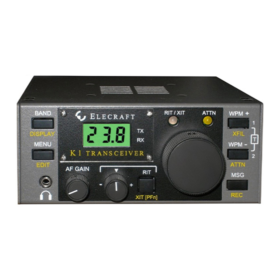
- Page 1 L E C R A F T T R A N S C E I V E R RIT / XIT ATTN BAND L E C R A F T DISPLAY XFIL MENU T R A N S C E I V E R EDIT ATTN AF GAIN...
- Page 2 CW T r a n s c e i v e r Owner’s Manual Revision F, January 24, 2002 Copyright 2002 Elecraft, All Rights Reserved Elecraft • www.elecraft.com P.O. Box 69 • Aptos, CA 95001-0069 (831) 662-8345 • Fax: (831) 662-0830...
-
Page 3: Table Of Contents
LECRAFT Table of Contents INTRODUCTION....................................3 SPECIFICATIONS ....................................5 PREPARATION FOR ASSEMBLY..............................6 FILTER BOARD....................................11 FRONT PANEL BOARD..................................17 RF BOARD, PART I................................... 25 ALIGNMENT AND TEST, PART I ..............................36 RF BOARD, PART II..................................42 ALIGNMENT AND TEST, PART II..............................46 FINAL ASSEMBLY.................................... -
Page 4: Elecraft
(see below), as well as shorter arms for desk-top use. support on our website, www.elecraft.com. We’d like to thank you for choosing the K1 transceiver, and hope it meets your expectations for operation both at home and in the field. - Page 5 Please use e-mail, rather than call, materials. You must send the unit at your expense to Elecraft, but we when possible since this gives us a written record of the details of will pay return shipping.
-
Page 6: Specifications
LECRAFT 2. Specifications Measurements were made using a 14-V supply and 50-ohm load. Transmitter General Power output 0-5 watts or higher; spurious and Size (H x W x D) harmonic content -40 dB @ 5 W Cabinet 2.2 x 5.2 x 5.6" (5.6 x 13 x 14 cm) Overall 2.4 x 5.2 x 7.1"... -
Page 7: Preparation For Assembly
K1 options, such as the KNB1 noise blanker, also plug in separate heat sink element. Each side panel includes a 10-32 directly. -
Page 8: Filter Board
K1-2 (2-band version) and K1-4 (4-band version) This manual covers all aspects of assembly for the two-band K1 (model K1-2). If you purchased a four-band K1 (model K1-4), you'll use the KFL1-4 assembly manual during assembly and alignment of the Filter board. You'll find instructions specific to the 4-band module at all... -
Page 9: Unpacking And Inventory
Second Digit Inventory First Digit We recommend that you do a complete inventory, using the parts lists in Appendix A. Start with the K1 Packing Box Parts list, Color Digit Multiplier which details the items you should find when you first open the Black box. - Page 10 PC boards. Tools Soldering The following specialized tools are supplied with the K1: When applying solder, use the minimum amount required to .050" (1.3 mm) and 5/64" (2 mm) Allen wrenches surround the component lead and make good contact with its Double-ended plastic alignment tool printed-circuit pad.
- Page 11 Photographs makes parts removal easier because it frees up both hands. If in doubt about a particular repair, ask for advice from Elecraft or Before beginning assembly, you should review the photographs in from someone else with PCB repair experience.
-
Page 12: Filter Board
Identify components using the photographs in the Filter board parts list in Appendix A. Place relays K1-K3 on the top side of the board. One end of each relay has a heavy line printed across the top to indicate the Locate the Filter printed circuit board (PCB), labeled "K1... - Page 13 LECRAFT Install the capacitors listed below. The list shows the At this point you’ll need to choose whether to set up the VFO capacitance value, followed by the labeling (in parentheses). After for 80-kHz or 150-kHz coverage (approx.). The smaller range installing each capacitor, bend the leads outward at about a 45- covers the most-used portion of every band, provides smoother degree angle to hold it in place until it is soldered and trimmed.
- Page 14 Identifying Toroid Cores Figure 4-1 Several toroidal inductors are used in the K1, including four on the Install the ceramic resonator, Z1, to the right of U1. (The Filter board. It is important to use the correct type of core. This ceramic resonator looks like a capacitor with three pins, and can be can be determined from the color and size.
- Page 15 LECRAFT Verify that the turns of L9 are not bunched together. They In the following steps you’ll install toroidal inductors L9- should be evenly spaced, and should occupy about 80-90% of the L12 (type T37-6 cores). They must be wound as indicated in the core.
- Page 16 LECRAFT Cut a 1" (25 mm) length of insulated hookup wire. Strip about The connectors to be installed in the following steps 1/8" (3 mm) of insulation off of each end. must be positioned correctly to avoid intermittent or unreliable operation. Install this wire between pins 2 and 10 of J2, in the upper right- hand corner of the board (Figure 4-5).
-
Page 17: Visual Inspection
(KAT1). The KAT1 option should be installed only after the P1 pin 3, P1 pin 4 > 100 k basic K1 kit has been completed and tested. At that time, the P1 pin 3, P1 pin 6 > 100 k jumper you installed between pins 2 and 10 of J2 will be removed. -
Page 18: Front Panel Board
Observe anti-static precautions with ICs and transistors. remaining pins. Do not use an excessive amount of solder. Locate the front panel PC board, which is labeled "K1 FP" Locate the Switch Spacing Tool (made of PC board along one edge. In the steps that follow, we will refer to the side material). - Page 19 LECRAFT If the socket does not appear to be seated flat on the PC Top of board, reheat these two pins while pressing on the socket. If the board leads of C4 hit the socket, trim them closer to the board. 1/16”...
- Page 20 LECRAFT Locate U4, a 78L06 voltage regulator, which has a TO-92 Before handling ICs and transistors in the following steps, package similar to Q1. Install U4 below the large hole. touch an unpainted, grounded metal surface. Touch an unpainted, grounded metal surface before Locate transistor Q1 (type 2N4124), which has a small, 3-lead handling the 2N7000 transistor in the next two steps.
- Page 21 LECRAFT Open the bag labeled MISCELLANEOUS and empty the contents into a shallow box or pan. This will prevent loss of any of the small hardware while allowing you to locate items as needed. Top Side Five sizes of 4-40 screws are used. All are black anodized except the 1/4"...
- Page 22 LECRAFT Inspect the solder side of U1's socket on the top side of the Caution: the LCD (DS1) and its pins are fragile. board. Make sure all pins are soldered, with no cold solder joints. Remove the LCD from its packing materials, being careful not Using a DMM, check every pair of adjacent pads on U1 on the to bend the pins.
- Page 23 LECRAFT Visual Inspection Type 1 Type 2 Using the parts placement drawings in Appendix F, re-check the orientation of the LEDs (D1 and D2), LCD (DS1), and all ICs. Examine both sides of the PC board closely for solder bridges, cold solder joints, or unsoldered components.
- Page 24 After removing any masking tape, turn the front panel face the others are rectangular, as shown in Figure 5-10. The caps are up, with the Elecraft logo at the top. installed by pressing them onto the switch plungers. Position the clear plastic LCD bezel over the large LCD opening, then secure it with four 2-56 screws (stainless steel) as shown in Figure 5-11.
- Page 25 LECRAFT Insert the Front Panel PC board assembly into the front panel The Allen wrenches are located in a small bag with the (Figure 5-12). The push-button switch caps should protrude slightly. MISCELLANEOUS items. These wrenches may have been oiled during manufacturing.
-
Page 26: Rf Board, Part I
LECRAFT 6. RF Board, Part I Locate the RF board and orient it as shown in Figure 6-1. This In Part I, the VFO (variable-frequency oscillator) and receiver illustration shows the major areas of the board. Receiver and VFO sections will be assembled. circuits occupy the front half;... - Page 27 Install relay K1, near the center of the board. Make sure the 2, and 3 on the Filter board align with the corresponding holes of pin 1 end (with the heavy line) is oriented as indicated by K1’s J6, 7 and 8 on the RF board.
- Page 28 LECRAFT Position 20-pin male right-angle connector P1 on the bottom Install the resistors listed below. R23 is at the left-front edge. of the RF board (Figure 6-5), but do not solder yet. Review Figure __ R23, 1.5 Ω (BRN-GRN-GOLD) ⇒ __ R7, 680 (BLUE_GRAY-BRN) 3-3 for correct placement.
- Page 29 LECRAFT Identify the two types of black, axial-lead diodes: 1N4007 and Install the resistor networks listed below, checking the part SB530. The 1N4007 is the smaller of the two. numbers carefully before installation. Orient the black dot or bar on each network towards pin 1 of its component outline.
- Page 30 LECRAFT Push the black keycap onto S1’s plunger until it snaps. Transistor Q4 (ZVN4424) is labeled on the back (the side Install the DC input jack, J4, at the back edge. The 3 leads on with smaller area), which is different from most TO-92 devices. the jack must be lined up with the slot-shaped holes in the The labeled side of Q4 must face the power switch, S1.
- Page 31 LECRAFT DC Voltage Checks Electrolytic capacitors are mounted vertically, so their PC board outlines are circular. The (+) lead must be installed in the hole Set power switch S1 to its OFF position, with the plunger out marked with a "+" symbol. The (+) lead is usually longer than the (extended toward the back).
- Page 32 Filter board only) for use at RFC8. This RF choke can be front. P2 must be seated flat against the board before soldering. installed at any time, and will have no effect on K1 alignment or testing on any band. Its function is to improve stability on 80 Install crystal X5, near the front edge of the board.
- Page 33 LECRAFT Locate the dark gray (ferrite) toroid cores. You should have Install T1 flat against the board, between U1 and U2. Insert four smaller cores (type FT37-43) and one larger core (FT50-43). the leads into its numbered holes as shown by the component The three inductors to be wound in the following steps, L2, T1, and outline.
- Page 34 LECRAFT On the top side of the RF board, locate the hole identified as (A) in Figure 6-9. (The label "S1" appears near the hole.) When working with the side panels in the following steps, place a soft cloth on your work surface to protect the paint. (A clean anti-static mat will also suffice.) Locate the two side panels and arrange them as shown in Figure 6-10, with the inside surfaces facing up.
- Page 35 LECRAFT Flat-head screws are more easily damaged than pan- Attach the side panels to the RF board using two 3/16" (4.8 heads. Do not use excessive force when tightening them. mm) flat-head screws per side panel. The side panels are attached using the 2-D fasteners that are already in place on the RF board.
- Page 36 LECRAFT With the assembly upside-down or resting on one side, plug the The switches should now be accessible, and the headphone front panel assembly into the RF board (Figure 6-13). Connector J1 jack should be even with the front panel. Also, the LEDs above the on the bottom of the front panel PC board mates with P1 on the VFO knob should be visible.
-
Page 37: Alignment And Test, Part I
Each of the push-button switches on the front panel has two functions, one activated by a TAP (short press) and the other Turn on power to the K1. If you see or smell smoke, or a activated by a HOLD (long press, about 1/2 second). The upper... - Page 38 J6, 7 and 8 on the RF board. Voltmeter Turn the K1 on. The LCD should show E 4 2 . You may also On power-up, the LCD shows the operating frequency, with hear one or more relays switching.
-
Page 39: Vfo Alignment
VFO Alignment VFO Range Test and locate C A L . To enable the operating Turn the K1 off and disconnect the power supply. M E N U frequency calibration display (O P F ), hold . The 100-Hz digit... -
Page 40: Receiver Alignment
. The current B A N D can be located with the K1. If you use a transmitter, be sure to band will be displayed (in MHz), followed by a 3-digit display (1 connect it to a dummy load and operate it at low power. - Page 41 Re-peak L3 and L4, then L7 and L8, until no further improvement is noted. Premix Coarse BFO Alignment Band 1 The K1 three crystal filter bandwidths are selected by holding Band 2 until you see F L 3 on the LCD. switch. Hold X F I L...
- Page 42 DMM in series between the K1 and the band Filter board installed, repeat the procedure for bands 3 and 4. power supply. Turn the K1 on and note the current: _____ mA. This completes receiver alignment. You can calibrate the dial on transmit rather than receive if desired, after completing Alignment and Test, Part II.
-
Page 43: Rf Board, Part Ii
In this section you’ll install the transmitter components. On the bottom of the board near the antenna jack, install a Turn off the K1 and disconnect the power supply. 1.50 k, 1% resistor at R36 (BRN-GRN-BLK-BRN), and a 226-ohm, 1% resistor at R37 (RED-RED-BLU-BLK). - Page 44 LECRAFT Identify the hole in the right side panel where the thermal TO-220 package transistors Q6 and Q7 look identical, but insulator will be placed (Figure 8-2). If the edge of the hole is not are different types. Locate the 2SC1969 (labeled "C1969"), Q7, completely smooth, use a large drill bit to de-burr the hole by hand.
- Page 45 LECRAFT Bend the center lead of Q7 slightly away from the side panel, T3 is wound on an FT37-43 core (dark gray), the smaller of forming it as shown in Figure 8-3. the two cores remaining. Start with the 1-2 winding, which uses 12 turns of red enamel wire (9", 22 cm).
- Page 46 LECRAFT If you plan to operate the K1 on 80 meters, and your K1 RF T4 uses a bi-filar winding, which means that two wires are board is revision D or earlier, you may need to make a minor wound on the core together. The wires for the two windings will be modification to the PC board.
-
Page 47: Alignment And Test, Part Ii
ICs. Also look Turn on the K1. You should see E 2 7 on the LCD due to the for shorts on both the top and bottom of the board in the missing Filter board. - Page 48 Switch to band 2, and set the VFO to about mid-band. If a 4-band Filter board is in use, refer to the KFL1-4 manual, page 19. Put the K1 into TUNE mode and adjust L3, L4, L7, and L8 All filters are shared between receiver and transmitter, so transmit for maximum output (refer to Figure 7-2 if necessary).
-
Page 49: Final Assembly
LECRAFT 10. Final Assembly Set the top cover upside-down in front of you, with the back Remove any masking tape from the top and bottom covers. edge facing away. Place the speaker over its holes, with the lugs to Use the technique described on page 23. the left. - Page 50 Insert the other wire into the pin 2 position. items have been provided as spares. Please read the Operation section, which follows, and try each of the K1's features. If you're Connect the other end of this cable to the speaker terminals.
-
Page 51: Operation
Any type of hand key, bug, or external keyer can be plugged into a Quick Reference, Appendix G, which shows the locations of the KEY jack, or you can connect a paddle and use the K1's built-in front-panel controls and describes each of the menu entries. -
Page 52: Switch Functions
LECRAFT Switch Functions Controls and Display a switch to access its upper function; a switch for 1/2 T A P H O L D second to access its lower function. All functions are listed below. The 3-digit LCD (liquid crystal display) shows the operating The "1"... -
Page 53: Using The Menu
LECRAFT Using the Menu To access the menu, tap . Scroll menu entries by tapping M E N U W P M + W P M - Hold to display a menu entry's parameter, which can then be changed by tapping . - Page 54 The F L x , B x , C A L , and S I G menu entries are typically used display, or to align the VFO. (VFO test and alignment is covered in during initial test and setup of the K1. B x and C A L are also used detail on page 38.) whenever you plug in a different Filter module to allow the K1 to display the correct frequencies.
- Page 55 D I S P L A Y shown, flashing slowly. In TUNE mode, power is shown in watts Band and Frequency Display: When you turn on the K1 or tap (see below). SWR can be displayed if the KAT1 ATU is installed.
- Page 56 I N P t o the transmitter is disabled. To restore the original power level H n d using the menu. You can key the K1 externally at up to 70 setting, hold again.
- Page 57 Using RIT During Message Repeat: You can use RIT (if it is directly to the K1's key jack. Set I N P to P D n or P D r . Messages are turned on) to listen above and below your receive frequency stored in EEPROM, so they won't be lost when power is turned off.
-
Page 58: Advanced Operating Features
The KTS1 received signals, so that you'll be exactly on frequency when you solves this problem by allowing you to rest the K1 on nearly any transmit. To spot a signal, select the S T P menu entry, hold rough surface (rock, dirt, etc.) and tilt the display upwards to the... -
Page 59: Circuit Details
The filter module includes the band-pass filters and crystals for the Microcontroller (MCU) U1 is used to control all K1 functions, and K1's pre-mix conversion scheme, in which a low-frequency (~3 doubles as the driver for the LCD, DS1. U1 runs at just below 4 MHz) VFO is subtracted from a high-frequency crystal oscillator to MHz. - Page 60 6 V. If both are closed, the voltage will be 0 V. If only All filters and the two crystals are switched by latching relays K1- one paddle is closed, an intermediate voltage results, either 2 V or 4 K3.
- Page 61 Since U5 is a low-dropout 8-volt regulator, the but is electrically connected between Q11 and U4 at the AF1 and K1's supply voltage can drop to as low as about 8.5 V without AF2 points. affecting the VFO frequency. U6 is a 6.0-volt regulator with a very tight tolerance of 2.5%.
-
Page 62: Parts List
Appendix A K1 Packing Box Parts List Revised 11-30-2000 PICTURE Designators Description Part Number Misc. RF PC board E100094 Left side panel E100097L Right side panel E100097R Front panel, silkscreened E100096SS Bottom cover, silkscreened E100098SS Top cover E100099 Bag, Misc. - Page 63 Appendix A K1 Packing Box Parts List Revised 11-30-2000 PICTURE Designators Description Part Number Misc (in envelope) Acrylic display bezel; for LCD (Front Panel) E100108 Misc (in envelope) Serial Number Label E980024 Speaker, 8-ohm, 1 watt E980032 Large knob, 1.25" dia, 0.25" shaft; Rogan #RB-67-3-M...
- Page 64 Appendix A K1 Front Panel Board Parts List PICTURE Designators Description Part Number C1, C2 82 pF NPO disc; label: "82" E530038 C5, C6 .01 µF, monolithic; label: "103" E530009 .047 µF, monolithic; label: "473" E530025 LED, dual, orange/green; LiteOn LTL-298WJ...
- Page 65 Appendix A K1 Front Panel Board Parts List PICTURE Designators Description Part Number 100 k, 10-turn potentiometer E520007 R2, R3 10 k potentiometer, linear taper E520005 3.92 k, 1/4W, 1%; color code: org-wht-red-brown E500031 12.7 k, 1/4W, 1%; color code: brn-red-violet-red E500063 22 Ω, 1/4W, 5%;...
- Page 66 Appendix A K1 Front Panel Board Parts List PICTURE Designators Description Part Number S1-S6 Switch, push button E640005 PIC16C77MCU, programmed ("K1"), 40 pins E610005 MAX518BCPA; Dual D/A converter, 8 pins Alt: MAX518ACPA E600013 24LC04B/P; EEPROM, 8 pins (alternate: 24WC04P) E600021...
- Page 67 Appendix A K1 RF Board Parts List PICTURE Designators Description Part Number C14, C15, C16, C19, C22, C28, C29, C51 .001 µF, monolithic; label: "102" E530001 C4, C6, C17, C18, C21, C23, C25, C36, C37, C40, C43, C44, C45, C47, C48, C49, C58, C60, C64, C66, C72, C74, C75, C76 .01 µF, monolithic;...
- Page 68 Appendix A K1 RF Board Parts List PICTURE Designators Description Part Number C13, C20 Ceramic trimmer capacitor, 8-50pF E530000 D2, D15 1N5711 Shottky diode, small glass pkg E560004 D5, D9-D14, D18 1N4007 PIN diode, large plastic pkg, black E560001 1N4753 zener diode, 36 V, 1 watt...
- Page 69 Appendix A K1 RF Board Parts List PICTURE Designators Description Part Number Keyer Jack, threaded bushing, Stereo, vertical mount (CUI/Stack p/n SJ-373??) E620027 Headphone jack, non-threaded, Stereo, with switch, horizontal mount E620028 J9, J10 2-pin, pads only (coax soldered to connections--see text) Latching Relay, 5V;...
- Page 70 Appendix A K1 RF Board Parts List PICTURE Designators Description Part Number 20 x 1 ,male, RA; 20 pin male, right angle. To Front Panel, E620029 2 pin, male, 0.1" conn with locking ramp; for speaker E620024 3 pin, male, 0.1" conn.; RF detector select E620007 2SC2166;...
- Page 71 Appendix A K1 RF Board Parts List PICTURE Designators Description Part Number R10, R33 470 Ω, 1/4W, 5%; color code: yellow-violet-brown E500003 680 Ω, 1/4W, 5%; color code: blue-gray-brown E500040 R12, R28 820 Ω, 1/4W, 5%; color code: gray-red-brown E500001 R1, R26, R27, R39 1.8 k, 1/4W, 5%;...
- Page 72 Appendix A K1 RF Board Parts List PICTURE Designators Description Part Number LM380N-8, 8 pin DIP, AF amplifier E600019 LM386N-1, 8 pin DIP, AF amplifier E600022 LT1252, 8 pin DIP, VFO Buffer; TX Buffer E600020 SA602AN, 8 pin DIP, TX Mixer; Prod. Detector...
- Page 73 (Refer to KFL1-4 manual for 4-band Filter board parts list) Note: All Inductors in table below are wound with #26 red enamel wire on T37-6 cores (Elecraft p/n E680013) All capacitors are NPO disc or monolithic, 5%, 0.2" lead spacing. Values are in pF.
- Page 74 Appendix A K1 Misc. Bag Parts List PICTURE Designators Description Part Number #4 int. tooth lockwasher (3 Spares) E700010 #4 split lockwasher (4 Spares) E700004 2-56,screw , 1/8", stainless steel, fillister head (2 spares) E700023 2-D Fastener E100078 4-40 nut, Steel-zinc (2 spares) E700011 4-40 screw, 1/4"...
- Page 75 Appendix A K1 Misc. Bag Parts List PICTURE Designators Description Part Number 2 pin female conn. Housing, 0.1” spacing, locking ramp. SPK-J1 (for speaker) E620021 ACC-P1 2.1mm male conn. (mates with DC power jack) E620032 Stereo 1/8” phone plug ACC-P2...
-
Page 76: Special Symbols
NOTCH CATHODE GREEN ANODE COUNT PINS STARTING AT PIN 1 AND GOING COUNTER- ANODE CLOCKWISE (8-PIN DIP SHOWN) ORANGE ANODE Special Symbols Elecraft Schematic Key Rev. Date Sht. = On bottom of PC board. W. Burdick 1 of 1 E.Swartz... - Page 77 Counter Amp. /OFFSET . 0 1 1 0 K 1 0 K Elecraft K1 Front Panel Board Offset 2 N 7 0 0 0 Rev. Date Sht. 1 0 1 1 1 2 1 3 1 4 1 5 1 6 1 7 1 8 1 9 2 0 W.
- Page 78 J 3 0 9 0 . 1 . 0 1 1 0 1 1 1 2 1 3 1 4 1 5 1 6 1 7 1 8 1 9 2 0 Elecraft K1 RF Board XFIL/TONE Rev. Date Sht. W. Burdick...
- Page 79 Power Transmit Attenuator 2 0 K 3 9 K KEYIN . 0 0 1 3.9K 2 N 4 1 2 4 Elecraft K1 RF Board 6 R _ 2 4.915 MHz RFC2 Rev. Date Sht. W. Burdick 3 3 0 22 µH...
- Page 80 If the KAT1 is not installed, J2 pins 2 and 10 must be connected using a jumper (see text). 2. See Parts List for values of all band-specific components. 3. K1-K3 are latching relays, and are shown in the RESET position. Elecraft K1 2-Band Filter Board Pins 5 and 6 of relays are not connected internally, but may be Rev.
-
Page 81: Block Diagram
11.915 - 12.065 MHz (40 m) AF AMP BAND- 4.915 MHz PASS FILTERS 15.000 MHz (40 m) PREMIX 3.085 - 2.935 DISPLAY Common Transmit Receive On Filter CONTROLS PC Board Appendix C K1 BLOCK DIAGRAM W. Burdick/E. Swartz Rev. A 8-16-00... -
Page 82: Photographs
Appendix D. K1 Assembly Photographs Completed K1 with top cover and side panels removed; Front Panel and 2-band Filter board shown Plugged into the RF board. Front Panel RF board with assembly bottom cover Attached (headphone jack is visible at left) -
Page 83: Troubleshooting
Transmitter and Keyer 80-99 just initialized if you install a new version of the firmware. All K1 parameters are set to defaults. Note: Components are identified by their PC board and reference designator. E N D P = 0 E N D : TX out of range (see specifications) For example, "FP-U1"... - Page 84 27 Filter board not E 2 7 If you saw the message , the I/O plugged in, or I/O Display and Control Circuits (20-39) controller (IOC, FIL-U1) did not respond to controller (FIL-U1) messages from the main processor (MCU, communication FP-U1).
- Page 85 VFO and Premixer (40-59) Receiver (60-79) Problem Troubleshooting Steps Problem Troubleshooting Steps 40 General VFO Note: Some VFO drift will always be present 60 Low (or no) audio If you hear normal audio output on one band problem; frequency due to aging of components and heating or output from receiver, but not all bands, see 62 jumps or drifts...
- Page 86 88 Power output If you stay in key-down (TUNE) mode for Transmitter and Keyer (80-99) fluctuates several seconds, it is normal to see some increase in power; this is due heating of the Problem Troubleshooting Steps final amplifier transistor. 80 General If power output is too low, go to 86 If power goes up and down significantly Transmitter problem...
- Page 87 The simple crystal oscillator shown in Figure 2 can be used in lieu of a Turn on the K1 and switch to the desired band. Use the menu to turn AGC commercial signal generator. It will run on voltages as low as 8 V, but 12 V or OFF.
- Page 88 Filter board). Expected: .07-.12 V. Actual: _______. Turn on the K1 and switch to the desired band. Set the power level to 3 13. RF band-pass filter: FIL-P2, pin 1. Expected: .06-.13 V. Actual: _____.
- Page 89 DC Voltage Table NOTES: Measurements listed for FIL-U1 apply only to the two-band Filter board; for 4-band Filter board voltages, refer to the KFL1-4 manual. Measurements were made with a 50-ohm dummy load connected and a supply voltage of 14 V. In general, your measurements should be within 10% of the values shown.
-
Page 90: Parts Placement Drawings
1 2 5 2 RFC4 RFC5 RFC3 ATTN OPER TEST (NOT GND) RFC9 RFC6 RFC1 SPKR K1 RF Rev. E 2001 ELECRAFT CUT=MONO K1 FP Rev. E 2001 ELECRAFT 3 5 8 (SOCKET) RFC1 RFC2 K1 FIL 2 Rev. D ELECRAFT 2000... -
Page 91: Quick Reference
LECRAFT QUICK REFERENCE Tap once to show band, LEDs tap twice to change bands Hold to select display RX: VFO freq or S-meter RIT / XIT - GREEN / ORANGE mode: normal, S-meter, TX: bargraph, 1 bar per watt ATTN - YELLOW Hold both for TUNE;...
Need help?
Do you have a question about the K1 and is the answer not in the manual?
Questions and answers