
Related Manuals for ELECRAFT K3S KAT3A


Summary of Contents for ELECRAFT K3S KAT3A
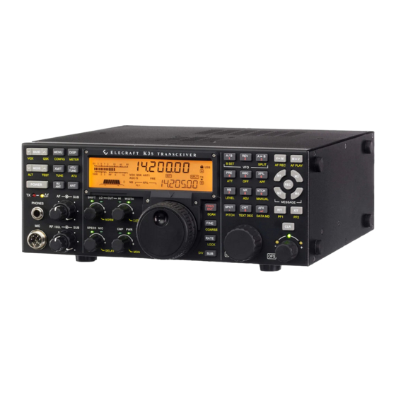
- Page 1 ERFORMANCE 160 – 6 M ETER RANSCEIVER LECRAFT KAT3A 100-W UTOMATIC NTENNA UNER NSTALLATION NSTRUCTIONS Rev A, June 2, 2015 Copyright © 2015, Elecraft, Inc. All Rights Reserved E740266...
-
Page 2: Table Of Contents
Installing the ANT2 Connector ......................... 11 Installing the KAT3A Module .......................... 11 Reinstalling the Sub Receiver Module ......................12 Replacing the Top Cover ..........................13 Enabling the KAT3A ..........................13 Elecraft manuals with color images may be downloaded from www.elecraft.com. -
Page 3: Introduction
Repair / Alignment Service (We want to make sure everyone succeeds!) If necessary, you may return your Elecraft product to us for repair or alignment. (Note: We offer unlimited email and phone support to get your kit running, so please try that route first as we can usually help you find the problem quickly.) -
Page 4: Preventing Electrostatic Discharge Damage
Elecraft products transferred by the purchaser to a third party, either by sale, gift or other method, who is not disclosed to Elecraft at the time of original order, are not covered by this warranty. If the Elecraft product is being bought indirectly for a third party, the third party's name and address must be provided to Elecraft at time of order to insure warranty coverage. -
Page 5: Preventing Esd Damage
Preventing ESD Damage ESD damage cannot occur if there is no voltage difference between the components and any object that touches them. That is how anti-static packaging works. Anti-static bags allow the static charge to flow over their surface, so that any part of the bag that touches the components inside are all at the same potential at all times. Anti- static foam keeps the leads of sensitive components at the same potential. -
Page 6: Preparing For Installation
2. Static dissipating work pad. Parts Included The following parts should be included in your kit. Check to ensure you have them all. If any parts are damaged or missing, contact Elecraft for replacements (see Customer Service and Support, page 3). ELECRAFT ILLUSTRATION DESCRIPTION QTY. -
Page 7: Installation Procedure
Installation Procedure Removing the Top Cover Disconnect power and all cables from your K3 or K3. Remove the nine screws to free the top cover as shown in Figure 1. After the cover is open, lift it gently to reach the speaker wire connector. Unplug the speaker then set the top cover aside in a safe place. Whenever you remove screws from a panel, if one screw seems too tight to loosen without damaging it, first loosen the other screws then try again. - Page 8 Remove the two 1-1/2” (38 mm) screws and lock washers shown in Figure 2. These screws extend all the way through the sub receiver module and secure it to standoffs mounted on the main RF board . Figure 2. Removing the KRX3 or KRX3A Module. In the following steps you will handle small TMP coaxial connectors.
-
Page 9: Removing The Right Side Panel
Removing the Right Side Panel Remove the hardware securing the heat sinks of U13 and U12 to the right side panel (see Figure 4). Be careful not to lose the lock washers inside the K3 /K3. Figure 4. U13 and U12 Mounting Hardware. Remove the screw holding the KANT3/KANT3A board to the standoff and the screw holding the 2D fastener to the rear panel near the SO239 antenna connector shown in Figure 5. -
Page 10: Removing The Kant3A/Kant3 Module
Remove the five screws shown in Figure 6 from the right side panel to release it. The side panel will lift off with the 2D fastener and standoff shown in Figure 5 attached. Figure 6. Removing Side Panel Hardware, Part 2. Removing the KANT3A/KANT3 Module Unplug the antenna connection to the KANT3A/KANT3A board (see Figure 7) then unplug it from the RF board and lift it out. -
Page 11: Installing The Ant2 Connector
Installing the ANT2 Connector Remove the dummy plug from the connector hole in the back panel. The plug is released by ANT 2 squeezing two tabs on opposite sides (see Figure 8). Figure 8. Installing ANT 2 Connector. Install the SO239 coaxial connector in the ANT 2 space using the hardware shown in Figure 8.If the optional sub receiver AUX RF connector is installed, remove the 3/8”... -
Page 12: Reinstalling The Sub Receiver Module
Plug the connectors on the wires leading to the jacks into the KAT3A board as shown in ANT 1 ANT 2 Figure 10. goes to the connector nearest the rear panel, and goes to the one farthest from the rear ANT 1 ANT 2 panel as shown. -
Page 13: Replacing The Top Cover
Replacing the Top Cover Hold the top cover above the K3 /K3, route the speaker wire under the stiffener bar and plug it into P25 on the KIO3A/KIO3 board at the left rear of the chassis as shown in Figure 11. Figure 11.
Need help?
Do you have a question about the K3S KAT3A and is the answer not in the manual?
Questions and answers