Juniper SRX340 Hardware Manual
Services gateway hardware guide
Hide thumbs
Also See for SRX340:
- Hardware manual (150 pages) ,
- Quick start manual (12 pages) ,
- How to set up (8 pages)
Table of Contents
Advertisement
Quick Links
Advertisement
Table of Contents
Troubleshooting

Subscribe to Our Youtube Channel
Related Manuals for Juniper SRX340


Summary of Contents for Juniper SRX340
- Page 1 SRX340 Services Gateway Hardware Guide Published 2020-08-26...
- Page 2 END USER LICENSE AGREEMENT The Juniper Networks product that is the subject of this technical documentation consists of (or is intended for use with) Juniper Networks software. Use of such software is subject to the terms and conditions of the End User License Agreement (“EULA”) posted at https://support.juniper.net/support/eula/.
-
Page 3: Table Of Contents
Overview SRX340 Services Gateway Overview | 16 SRX340 Services Gateway Description | 16 SRX340 Services Gateway Field Replaceable Units Overview | 16 Benefits of the SRX340 Services Gateway | 17 SRX340 Chassis | 17 SRX340 Services Gateway Chassis Overview | 18... - Page 4 SRX340 Transceiver Specifications and Pinouts | 37 SRX340 Transceiver Support | 37 RJ-45 Connector Pinouts for the SRX340 Services Gateway Ethernet Port | 38 RJ-45 Connector Pinouts for the SRX340 Services Gateway Console Port | 38 Mini-USB Connector Pinouts for the SRX340 Services Gateway Console Port | 39...
- Page 5 Powering Off the SRX340 Services Gateway | 52 Connecting the SRX340 to External Devices | 54 Connecting the Dial-Up Modem to the Console Port on the SRX340 Services Gateway | 54 Connecting to the SRX340 Services Gateway CLI Using a Dial-Up Modem | 55...
- Page 6 Locating the SRX340 Services Gateway Chassis Serial Number and Agency Labels | 76 Locating the SRX340 Services Gateway Mini-Physical Interface Module Serial Number Label | 77 Listing the SRX340 Services Gateway Component Details with the CLI | 77 Required Tools and Parts for Packing the SRX340 Services Gateway | 78...
- Page 7 AC Power Electrical Safety Guidelines | 107 SRX340 Services Gateway Agency Approvals | 108 SRX340 Services Gateway Acoustic Noise Compliance Statements | 109 SRX340 Services Gateway EMC Requirements | 110 Canada | 110 European Community | 110 Israel | 110...
-
Page 8: About The Documentation
Use this guide to install hardware and perform initial software configuration, routine maintenance, and troubleshooting for the SRX340 Services Gateway. After completing the installation and basic configuration procedures covered in this guide, refer to the Junos OS documentation for information about further software configuration. -
Page 9: Merging A Full Example
If the example configuration contains the top level of the hierarchy (or multiple hierarchies), the example is a full example. In this case, use the load merge command. If the example configuration does not start at the top level of the hierarchy, the example is a snippet. In this case, use the load merge relative command. -
Page 10: Merging A Snippet
Merging a Snippet To merge a snippet, follow these steps: 1. From the HTML or PDF version of the manual, copy a configuration snippet into a text file, save the file with a name, and copy the file to a directory on your routing platform. For example, copy the following snippet to a file and name the file ex-script-snippet.conf. - Page 11 Table 1: Notice Icons Icon Meaning Description Informational note Indicates important features or instructions. Caution Indicates a situation that might result in loss of data or hardware damage. Warning Alerts you to the risk of personal injury or death. Laser warning Alerts you to the risk of personal injury from a laser.
- Page 12 Table 2: Text and Syntax Conventions (continued) Convention Description Examples Italic text like this Represents variables (options for Configure the machine’s domain which you substitute a value) in name: commands or configuration [edit] statements. root@# set system domain-name domain-name Text like this Represents names of configuration To configure a stub area, include statements, commands, files, and...
-
Page 13: Documentation Feedback
URL or page number, and software version (if applicable). Requesting Technical Support Technical product support is available through the Juniper Networks Technical Assistance Center (JTAC). If you are a customer with an active Juniper Care or Partner Support Services support contract, or are... -
Page 14: Self-Help Online Tools And Resources
JTAC hours of operation—The JTAC centers have resources available 24 hours a day, 7 days a week, 365 days a year. Self-Help Online Tools and Resources For quick and easy problem resolution, Juniper Networks has designed an online self-service portal called the Customer Support Center (CSC) that provides you with the following features: Find CSC offerings: https://www.juniper.net/customers/support/... -
Page 15: Overview
C HAPTER Overview SRX340 Services Gateway Overview | 16 SRX340 Chassis | 17 SRX340 Cooling System | 23 SRX340 Power System | 24... -
Page 16: Srx340 Services Gateway Overview
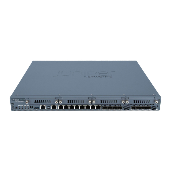
The SRX340 Services Gateway has a capacity of 3 gigabits per second (Gbps) and is 1 rack unit (U) tall. The services gateway has eight 1 G Ethernet ports, eight 1 G SFP ports, one management port, 4 GB of DRAM memory, 8 GB of flash memory, and four Mini-Physical Interface Module (Mini-PIM) slots. -
Page 17: Benefits Of The Srx340 Services Gateway
Replacing Mini-Physical Interface Modules in the SRX340 Services Gateway | 67 Benefits of the SRX340 Services Gateway High performance—The SRX340 supports up to 3-Gbps firewall and 600-Mbps IPsec VPN, and is suited for midsize distributed enterprise branch office deployments. Simplified deployment with minimal manual intervention—The Zero Touch Provisioning (ZTP) feature enables you to provision and configure the SRX300 line automatically, thereby reducing operational complexity and simplifying the provisioning of new sites. -
Page 18: Srx340 Services Gateway Chassis Overview
SRX340 Services Gateway Chassis Overview The SRX340 Services Gateway chassis is a rigid sheet metal structure that houses all of the other services gateway components. The chassis measures 1.72 in. (4.36 cm) high, 17.36 in. (44.09 cm) wide, and 14.57 in. - Page 19 Table 3: SRX340 Services Gateway Front Panel Components (continued) Callout Component Description 2, 8 Console ports Serial—Connects a laptop to the services gateway for CLI management. The port uses an RJ-45 serial connection and supports the RS-232 (EIA-232) standard. USB—Connects a laptop to the services gateway for CLI management through a USB interface.
- Page 20 Table 3: SRX340 Services Gateway Front Panel Components (continued) Callout Component Description 1-GbE Ethernet ports Eight LAN ports (0/0 to 0/7), which are MACsec capable. The ports have the following characteristics: Use an RJ-45 connector Operate in full-duplex and half-duplex modes...
-
Page 21: Management Port Leds
Table 4: SRX340 Services Gateway Front Panel LEDs Component Description ALARM Solid amber (noncritical alarm) Solid red (critical alarm) Off (no alarms) STAT Solid green (operating normally) Solid red (error detected) Solid green (receiving power) Solid red (power failure) Off (no power) -
Page 22: Srx340 Services Gateway Back Panel
Blinking green—There is activity on the 1 G link. Off—There is no link activity. SRX340 Services Gateway Back Panel Figure 3 on page 22 shows the back panel of the SRX340 Services Gateway and Table 7 on page 22 lists the components on the back panel. -
Page 23: Srx340 Services Gateway Interface Modules Overview
SRX340 Cooling System The cooling system for the SRX340 Services Gateway includes four fixed fans. The fans draw air through vents on the front of the chassis and exhaust the air through the back of the chassis. The airflow produced... -
Page 24: Srx340 Power System
SRX340 Services Gateway chassis. Figure 4: Airflow Through the SRX340 Services Gateway Chassis RELATED DOCUMENTATION Maintaining the SRX340 Services Gateway Cooling System Components | 67 SRX340 Power System IN THIS SECTION Understanding the SRX340 Services Gateway Power Supply | 25... -
Page 25: Understanding The Srx340 Services Gateway Power Supply
Understanding the SRX340 Services Gateway Power Supply The SRX340 Services Gateway uses a fixed, internal AC power supply. The power supply distributes the different output voltages to the device components according to their voltage requirements. The power supply is fixed in the chassis and is not field-replaceable. The power supply has a single AC appliance inlet that requires a dedicated AC power feed. - Page 26 NOTE: In North America, AC power cords must not exceed 4.5 m (approximately 14.75 ft) in length, to comply with National Electrical code (NEC) Section 400-8 (NFPA 75, 5-2.2) and 210-52, and Canadian Electrical Code (CEC) Section 4-010(3). Table 9 on page 26 provides power cord specifications, and Figure 5 on page 26 depicts the plug on the...
- Page 27 RELATED DOCUMENTATION SRX340 Services Gateway Electrical Wiring Guidelines | 32...
-
Page 28: Site Planning, Preparation, And Specifications
C HAPTER Site Planning, Preparation, and Specifications Site Preparation Checklist for the SRX340 Services Gateway | 29 SRX340 Site Guidelines and Requirements | 31 SRX340 Transceiver Specifications and Pinouts | 37... -
Page 29: Site Preparation Checklist For The Srx340 Services Gateway
Table 10 on page 29 provides a checklist of tasks you need to perform when preparing a site for installing the SRX340 Services Gateway. Table 10: Site Preparation Checklist for SRX340 Services Gateway Installation Performed Item or Task Additional Information... - Page 30 Table 10: Site Preparation Checklist for SRX340 Services Gateway Installation (continued) Performed Item or Task Additional Information Date Notes Secure the rack to the floor Connecting the SRX340 Services and building structure. Gateway to the Building Structure Cabinet Requirements Verify that your cabinet “Cabinet Requirements for the SRX340...
-
Page 31: Srx340 Site Guidelines And Requirements
Cabinet Requirements for the SRX340 Services Gateway | 36 General Site Installation Guidelines for the SRX340 Services Gateway The following precautions help you plan an acceptable operating environment for your SRX340 Services Gateway and avoid environmentally caused equipment failures: For the cooling system to function properly, the airflow around the chassis must be unrestricted. Allow sufficient clearance between the front and back of the chassis and adjacent equipment. -
Page 32: Srx340 Services Gateway Environmental Specifications
SRX340 Services Gateway Environmental Specifications Table 11 on page 32 provides the required environmental conditions for normal SRX340 Services Gateway operations. Table 11: Environmental Specifications for the SRX340 Services Gateway Description Value Altitude No performance degradation up to 10,000 ft (3048 m) - Page 33 Table 12: Site Electrical Wiring Guidelines for the SRX340 Services Gateway Site Wiring Factor Guideline Signaling Limitations To ensure that signaling functions optimally: Install wires correctly. Improperly installed wires can emit radio interference. Do not exceed the recommended distances or pass wires between buildings.
-
Page 34: Srx340 Services Gateway Grounding Specifications
SRX340 Services Gateway Grounding Specifications To meet safety and electromagnetic interference (EMI) requirements and to ensure proper operation, the SRX340 Services Gateway must be adequately grounded before power is connected. You must provide a grounding lug to connect the services gateway to earth ground. -
Page 35: Srx340 Services Gateway Clearance Requirements For Airflow And Hardware Maintenance
SRX340 Services Gateway Clearance Requirements for Airflow and Hardware Maintenance When planning the installation site for the SRX340 Services Gateway, you need to allow sufficient clearance around the device. Consider the following: For the operating temperature of the services gateway to be optimal, the airflow around the chassis must be unrestricted. -
Page 36: Rack Requirements For The Srx340 Services Gateway
(top and bottom mounting hole). Cabinet Requirements for the SRX340 Services Gateway You can install the SRX340 Services Gateway in a 19 in. (48.7 cm) cabinet as defined in Cabinets, Racks, Panels, and Associated Equipment (document number EIA-310-D) published by the Electronic Industries Alliance (http://www.ecaus.org/eia/site/index.html). -
Page 37: Srx340 Transceiver Specifications And Pinouts
A cabinet larger than the minimum required provides better airflow and reduces the chance of overheating. When you mount the SRX340 Services Gateway in a cabinet, you must ensure that ventilation through the cabinet is sufficient to prevent overheating. Consider the following when planning for chassis cooling: Ensure that the cool air supply you provide through the cabinet can adequately dissipate the thermal output of the services gateway. -
Page 38: Rj-45 Connector Pinouts For The Srx340 Services Gateway Ethernet Port
Tool enables you to search by product, displaying all the transceivers supported on that device, or category, by interface speed or type. The list of supported transceivers for the SRX340 is located at https://apps.juniper.net/hct/product/#prd=SRX340. RJ-45 Connector Pinouts for the SRX340 Services Gateway Ethernet Port Table 15 on page 38 describes the RJ-45 connector pinouts for the Ethernet port. -
Page 39: Mini-Usb Connector Pinouts For The Srx340 Services Gateway Console Port
Mini-USB Connector Pinouts for the SRX340 Services Gateway Console Port The SRX340 Services Gateway has two console ports: an RJ-45 Ethernet port and a mini-USB Type-B port. If your management device (laptop or PC) does not have a DB-9 male connector pin or an RJ-45... - Page 40 Table 17: Mini-USB Type-B Connector Pinouts for the Services Gateway Console Port (continued) Signal Cable Color Description Could be not connected (N/C), connected to ground (GND), or used as an attached device presence indicator Black Ground...
-
Page 41: Initial Installation And Configuration
C HAPTER Initial Installation and Configuration SRX340 Installation Overview | 42 Unpacking and Mounting the SRX340 | 44 Connecting the SRX340 to Power | 48 Connecting the SRX340 to External Devices | 54 Configuring Junos OS on the SRX340 | 56... -
Page 42: Srx340 Installation Overview
SRX340 Services Gateway Autoinstallation Overview | 42 SRX340 Services Gateway Installation Overview After you have prepared the site for installation and unpacked the SRX340 Services Gateway, you are ready to install the device. It is important to proceed through the installation process in the following order: 1. - Page 43 autoinstallation feature enables you to deploy multiple services gateways from a central location in the network. If you are setting up many devices, autoinstallation can help automate the configuration process by loading configuration files onto new or existing devices automatically over the network. You can use either the J-Web interface or the CLI to configure a device for autoinstallation.
-
Page 44: Unpacking And Mounting The Srx340
Phillips (+) screwdriver, number 2 Blank panels to cover any slots not occupied by a component The SRX340 Services Gateway is shipped in a cardboard carton and secured with foam packing material. The carton also contains an accessory box and quick start instructions. -
Page 45: Verifying Parts Received With The Srx340 Services Gateway
Verifying Parts Received with the SRX340 Services Gateway The SRX340 Services Gateway shipment package contains a packing list. Check the parts in the shipment against the items on the packing list. The packing list specifies the part numbers and carries a brief description of each part in your order. -
Page 46: Preparing The Srx340 Services Gateway For Rack-Mount Installation
Verify that the site meets the requirements described in “Site Preparation Checklist for the SRX340 Services Gateway” on page Verify that you have the following parts available in your rack-mounting kit for the SRX340 Services Gateway: Rack-mounting brackets Eight mounting screws to attach the mounting brackets to the chassis of the services gateway... -
Page 47: Installing The Srx340 Services Gateway In A Rack
Installing the SRX340 Services Gateway in a Rack You can front-mount the SRX340 Services Gateway in a rack. Many types of racks are acceptable, including four-post (telco) racks, enclosed cabinets, and open-frame racks. NOTE: If you are installing multiple devices in one rack, install the lowest one first and proceed upward in the rack. -
Page 48: Connecting The Srx340 To Power
RELATED DOCUMENTATION Configuring Junos OS on the SRX340 | 56 Connecting the SRX340 to Power IN THIS SECTION Required Tools and Parts for Grounding the SRX340 Services Gateway | 49 Connecting the SRX340 Services Gateway Grounding Cable | 49... -
Page 49: Required Tools And Parts For Grounding The Srx340 Services Gateway
Connecting the SRX340 Services Gateway to an AC Power Supply | 51 Powering On the SRX340 Services Gateway | 52 Powering Off the SRX340 Services Gateway | 52 Required Tools and Parts for Grounding the SRX340 Services Gateway To ground and to provide power to the services gateway, you need the following tools:... - Page 50 5. Secure the grounding cable lug to the grounding point, first with the washer, then with the screws. Figure 9: Connecting the Grounding Cable to the SRX340 Services Gateway 6. Dress the grounding cable and verify that it does not touch or block access to the services gateway components and that it does not drape where people could trip on it.
-
Page 51: Connecting The Srx340 Services Gateway To An Ac Power Supply
51. Verify that the power cord does not block the air exhaust and access to services gateway components or drape where people could trip on it. Figure 10: Connecting the SRX340 Services Gateway to an AC Power Supply CAUTION: We recommend using a surge protector for the power connection. -
Page 52: Powering On The Srx340 Services Gateway
Powering On the SRX340 Services Gateway To power on the services gateway: 1. Insert the power cord plug into an AC power source receptacle. 2. Turn on the power to the AC power receptacle. The device starts automatically as the power supply completes its startup sequence. The PWR LED lights during startup and remains on when the device is operating normally. - Page 53 CAUTION: Use the forced shutdown method as a last resort to recover the services gateway if the services gateway operating system is not responding to the graceful shutdown method. WARNING: Do not press the Power button while the device is shutting down. CAUTION: Forced shutdown can result in data loss and corruption of the file system.
-
Page 54: Connecting The Srx340 To External Devices
Connecting the SRX340 to External Devices IN THIS SECTION Connecting the Dial-Up Modem to the Console Port on the SRX340 Services Gateway | 54 Connecting to the SRX340 Services Gateway CLI Using a Dial-Up Modem | 55 Connecting the Dial-Up Modem to the Console Port on the SRX340 Services... -
Page 55: Connecting To The Srx340 Services Gateway Cli Using A Dial-Up Modem
RJ-45 to DB-9 adapter and the Ethernet cable supplied with the services gateway. Connecting to the SRX340 Services Gateway CLI Using a Dial-Up Modem To remotely connect to the CLI through a dial-up modem connected to the console port on the services gateway: 1. -
Page 56: Configuring Junos Os On The Srx340
Viewing Factory-Default Settings | 64 SRX340 Services Gateway Software Configuration Overview The services gateway is shipped with the Juniper Networks Junos operating system (Junos OS) preinstalled and ready to be configured when the device is powered on. You can perform the initial software configuration of the services gateway by using the browser-based setup wizard or by using the command-line interface (CLI). - Page 57 (logical) untrust ISP assigned* *Only if the LTE Mini-PIM is present The SRX340 device is shipped with the following services and protocols enabled by default: Table 24: Services, Protocols, and Startup Mode Services Protocols Device Startup Mode RSTP (all interfaces)
-
Page 58: Initial Configuration
2. Connect the other end of the Ethernet cable to the management device. Figure 11: Connecting the SRX340 to a Management Device Management port RJ-45 cable Ethernet port The SRX340 functions as a DHCP server and automatically assigns an IP address to the laptop. -
Page 59: Initial Configuration Using Cli
3. Ensure that the management device acquires an IP address on the 192.168.1.0/24 network from the device. If an IP address is not assigned to the management device, manually configure an IP address in the 192.168.1.0/24 network. NOTE: Do not assign the 192.168.1.1 IP address to the management device, as this IP address is assigned to the services gateway. - Page 60 To download the driver for Windows OS, select 6.5 from the Version drop-down list. To download the driver for Mac OS, select 4.10 from the Version drop-down list. Figure 12: Connecting to the Console Port on the SRX340 Services Gateway 4. Start your asynchronous terminal emulation application (such as Microsoft Windows HyperTerminal) and select the appropriate COM port to use (for example, COM1).
-
Page 61: Plug And Play
The SRX340 already has factory-default settings configured to make it a plug and play device. So all you have to do to get the SRX340 up and running is connect it to your LAN and WAN networks. 1. Connect the WAN network to port 0/0 to obtain a dynamic IP address. -
Page 62: Customize The Configuration Using J-Web
After you complete these steps, you can start using the SRX340 on your network right away. You can go back and customize the settings at anytime. Customize the Configuration Using J-Web You can modify the configuration using J-Web. Have the following information ready before you start the... - Page 63 c. Enter the root authentication password. d. (Optional) Add user accounts. e. Click Next. 4. Set the time and configure the DNS server: a. Set the time manually or configure an NTP server. b. Select the time zone from the drop-down box. c.
-
Page 64: Viewing Factory-Default Settings
Viewing Factory-Default Settings To view the factory-default settings on your services gateway: 1. Log in as the root user and provide your credentials. 2. View the list of default configuration files: user@host>file list /etc/config 3. View the required default configuration file. user@host>... -
Page 65: Maintaining Components
C HAPTER Maintaining Components Maintaining the SRX340 Components | 66... -
Page 66: Maintaining The Srx340 Components
Maintaining the SRX340 Components IN THIS SECTION Required Tools and Parts for Maintaining the SRX340 Services Gateway Hardware Components | 66 Routine Maintenance Procedures for the SRX340 Services Gateway | 66 Maintaining the SRX340 Services Gateway Cooling System Components | 67... -
Page 67: Maintaining The Srx340 Services Gateway Cooling System Components
Replacing Mini-Physical Interface Modules in the SRX340 Services Gateway The Mini-PIMs available on the SRX340 Services Gateway are not hot-swappable. You need to power off the device before removing or installing Mini-PIMs. - Page 68 SEE ALSO SRX340 Services Gateway Field Replaceable Units Overview | 16...
-
Page 69: Troubleshooting Hardware
C HAPTER Troubleshooting Hardware Troubleshooting the SRX340 | 70... -
Page 70: Troubleshooting The Srx340
IN THIS SECTION Troubleshooting Resources for the SRX340 Services Gateway Overview | 70 Troubleshooting Chassis and Interface Alarm Messages on the SRX340 Services Gateway | 70 Troubleshooting the Power System on the SRX340 Services Gateway | 71 Using the RESET CONFIG Button | 72... -
Page 71: Troubleshooting The Power System On The Srx340 Services Gateway
Table 25: SRX340 Services Gateway Chassis Alarm Conditions and Corrective Actions Alarm Component Alarm Conditions Action Severity Boot media The services gateway boots If the internal flash memory fails at startup, the Amber from an alternate boot device. services gateway automatically boots itself from (minor) the alternative boot device (USB storage device). -
Page 72: Using The Reset Config Button
Table 26 on page 72 describes the status of the PWR LED. Table 26: SRX340 Services Gateway Power LED Status LED Status Meaning Possible Cause and Corrective Action Green Device is receiving power. Normal indication. No action is required. Amber Indicates that the power button Normal indication. -
Page 73: Changing The Reset Config Button Behavior
By default, pressing and holding the RESET CONFIG button for 15 seconds or more—until the Status LED is solid amber — deletes all configurations on the device, including the backup configurations and rescue configuration, and loads and commits the factory configuration. Changing the RESET CONFIG Button Behavior You can change the default operation of the RESET CONFIG button by limiting how the button resets the services gateway:... -
Page 74: Contacting Customer Support And Returning The Chassis Or Components
C HAPTER Contacting Customer Support and Returning the Chassis or Components Returning the SRX340 Chassis or Components | 75... -
Page 75: Returning The Srx340 Chassis Or Components
Contacting Customer Support Once you have located the serial numbers of the device or component, you can return the device or component for repair or replacement. For this, you need to contact Juniper Networks Technical Assistance Center (JTAC). You can contact JTAC 24 hours a day, 7 days a week, using any of the following methods: On the Web: Using the Service Request Manager link at https://support.juniper.net/support/... -
Page 76: Returning A Srx340 Services Gateway Component To Juniper Networks
Returning a SRX340 Services Gateway Component to Juniper Networks To return an SRX340 Services Gateway or component to Juniper Networks for repair or replacement: 1. Determine the part number and serial number of the services gateway or component. -
Page 77: Locating The Srx340 Services Gateway Mini-Physical Interface Module Serial Number Label
Mini-PIMs, depending on the placement of components on the Mini-PIM. Listing the SRX340 Services Gateway Component Details with the CLI Before contacting Juniper Networks to request an RMA, you must find the serial number on the SRX340 Services Gateway or component. -
Page 78: Required Tools And Parts For Packing The Srx340 Services Gateway
Required Tools and Parts for Packing the SRX340 Services Gateway To remove the components from the SRX340 Services Gateway or to remove the services gateway from a rack, you need the following tools and parts: Electrostatic bag or antistatic mat for each component Electrostatic discharge (ESD) grounding wrist strap Flat-blade screwdriver, approximately 1/4 in. -
Page 79: Packing Srx340 Services Gateway Components For Shipment
12. Write the Return Materials Authorization (RMA) number on the exterior of the box to ensure proper tracking. Packing SRX340 Services Gateway Components for Shipment Follow these guidelines for packing and shipping individual components of the services gateway: When you return a component, make sure that it is adequately protected with packing materials and packed so that the pieces are prevented from moving around inside the carton. -
Page 80: Safety And Compliance Information
Action to Take After an Electrical Accident | 106 General Electrical Safety Guidelines and Warnings | 106 AC Power Electrical Safety Guidelines | 107 SRX340 Services Gateway Agency Approvals | 108 SRX340 Services Gateway Acoustic Noise Compliance Statements | 109 SRX340 Services Gateway EMC Requirements | 110... -
Page 82: Definitions Of Safety Warning Levels
Definitions of Safety Warning Levels The documentation uses the following levels of safety warnings (there are two Warning formats): NOTE: You might find this information helpful in a particular situation, or you might overlook this important information if it was not highlighted in a Note. CAUTION: You need to observe the specified guidelines to prevent minor injury or discomfort to you or severe damage to the device. - Page 84 WARNING: This symbol means danger. You are in a situation that could cause bodily injury. Before you work on any equipment, be aware of the hazards involved with electrical circuitry and be familiar with standard practices for preventing accidents. Waarschuwing Dit waarschuwingssymbool betekent gevaar. U verkeert in een situatie die lichamelijk letsel kan veroorzaken.
-
Page 85: General Safety Guidelines And Warnings
Varning! Denna varningssymbol signalerar fara. Du befinner dig i en situation som kan leda till personskada. Innan du utför arbete på någon utrustning måste du vara medveten om farorna med elkretsar och känna till vanligt förfarande för att förebygga skador. General Safety Guidelines and Warnings The following guidelines help ensure your safety and protect the device from damage. - Page 86 Some parts of the chassis, including AC and DC power supply surfaces, power supply unit handles, SFB card handles, and fan tray handles might become hot. The following label provides the warning of the hot surfaces on the chassis: Always ensure that all modules, power supplies, and cover panels are fully inserted and that the installation screws are fully tightened.
-
Page 87: Restricted Access Warning
Restricted Access Warning... - Page 88 WARNING: This unit is intended for installation in restricted access areas. A restricted access area is an area to which access can be gained only by service personnel through the use of a special tool, lock and key, or other means of security, and which is controlled by the authority responsible for the location.
- Page 89 ¡Atención! Esta unidad ha sido diseñada para instalarse en áreas de acceso restringido. Área de acceso restringido significa un área a la que solamente tiene acceso el personal de servicio mediante la utilización de una herramienta especial, cerradura con llave, o algún otro medio de seguridad, y que está...
-
Page 90: Qualified Personnel Warning
Qualified Personnel Warning WARNING: Only trained and qualified personnel should install or replace the device. Waarschuwing Installatie en reparaties mogen uitsluitend door getraind en bevoegd personeel uitgevoerd worden. Varoitus Ainoastaan koulutettu ja pätevä henkilökunta saa asentaa tai vaihtaa tämän laitteen. Attention Tout installation ou remplacement de l'appareil doit être réalisé... - Page 91 Always use an ESD wrist strap when you are handling components that are subject to ESD damage, and make sure that it is in direct contact with your skin. If a grounding strap is not available, hold the component in its antistatic bag (see Figure 14 on page in one hand and touch the exposed, bare metal of the device with the other hand immediately before inserting the component into the device.
-
Page 92: Fire Safety Requirements
In addition, you should establish procedures to protect your equipment in the event of a fire emergency. Juniper Networks products should be installed in an environment suitable for electronic equipment. We recommend that fire suppression equipment be available in the event of a fire in the vicinity of the equipment and that all local fire, safety, and electrical codes and ordinances be observed when you install and operate your equipment. -
Page 93: Laser And Led Safety Guidelines And Warnings
To keep warranties effective, do not use a dry chemical fire extinguisher to control a fire at or near a Juniper Networks device. If a dry chemical fire extinguisher is used, the unit is no longer eligible for coverage under a service agreement. -
Page 94: Class 1 Laser Product Warning
WARNING: Unterminated optical connectors can emit invisible laser radiation. The lens in the human eye focuses all the laser power on the retina, so focusing the eye directly on a laser source—even a low-power laser—could permanently damage the eye. Class 1 Laser Product Warning WARNING: Class 1 laser product. -
Page 95: Class 1 Led Product Warning
Class 1 LED Product Warning WARNING: Class 1 LED product. Waarschuwing Klasse 1 LED-product. Varoitus Luokan 1 valodiodituote. Attention Alarme de produit LED Class I. Warnung Class 1 LED-Produktwarnung. Avvertenza Avvertenza prodotto LED di Classe 1. Advarsel LED-produkt i klasse 1. Aviso Produto de classe 1 com LED. -
Page 96: Laser Beam Warning
Laser Beam Warning WARNING: Do not stare into the laser beam or view it directly with optical instruments. Waarschuwing Niet in de straal staren of hem rechtstreeks bekijken met optische instrumenten. Varoitus Älä katso säteeseen äläkä tarkastele sitä suoraan optisen laitteen avulla. Attention Ne pas fixer le faisceau des yeux, ni l'observer directement à... -
Page 97: Radiation From Open Port Apertures Warning
Radiation from Open Port Apertures Warning WARNING: Because invisible radiation might be emitted from the aperture of the port when no fiber cable is connected, avoid exposure to radiation and do not stare into open apertures. Waarschuwing Aangezien onzichtbare straling vanuit de opening van de poort kan komen als er geen fiberkabel aangesloten is, dient blootstelling aan straling en het kijken in open openingen vermeden te worden. -
Page 98: Maintenance And Operational Safety Guidelines And Warnings
Maintenance and Operational Safety Guidelines and Warnings IN THIS SECTION Battery Handling Warning | 99 Jewelry Removal Warning | 100 Lightning Activity Warning | 102 Operating Temperature Warning | 103 Product Disposal Warning | 105 While performing the maintenance activities for devices, observe the following guidelines and warnings:... -
Page 99: Battery Handling Warning
Battery Handling Warning WARNING: Replacing a battery incorrectly might result in an explosion. Replace a battery only with the same or equivalent type recommended by the manufacturer. Dispose of used batteries according to the manufacturer's instructions. Waarschuwing Er is ontploffingsgevaar als de batterij verkeerd vervangen wordt. Vervang de batterij slechts met hetzelfde of een equivalent type dat door de fabrikant aanbevolen is. -
Page 100: Jewelry Removal Warning
Jewelry Removal Warning... - Page 101 WARNING: Before working on equipment that is connected to power lines, remove jewelry, including rings, necklaces, and watches. Metal objects heat up when connected to power and ground and can cause serious burns or can be welded to the terminals. Waarschuwing Alvorens aan apparatuur te werken die met elektrische leidingen is verbonden, sieraden (inclusief ringen, kettingen en horloges) verwijderen.
-
Page 102: Lightning Activity Warning
se conectan a la alimentación y a tierra, lo que puede ocasionar quemaduras graves o que los objetos metálicos queden soldados a los bornes. Varning! Tag av alla smycken (inklusive ringar, halsband och armbandsur) innan du arbetar på utrustning som är kopplad till kraftledningar. Metallobjekt hettas upp när de kopplas ihop med ström och jord och kan förorsaka allvarliga brännskador;... -
Page 103: Operating Temperature Warning
Operating Temperature Warning... - Page 104 40° C. Para evitar a restrição à circulação de ar, deixe pelo menos um espaço de 15,2 cm à volta das aberturas de ventilação. ¡Atención! Para impedir que un encaminador de la serie Juniper Networks switch se recaliente, no lo haga funcionar en un área en la que se supere la temperatura ambiente máxima recomendada de 40°...
-
Page 105: Product Disposal Warning
Varning! Förhindra att en Juniper Networks switch överhettas genom att inte använda den i ett område där den maximalt rekommenderade omgivningstemperaturen på 40° C överskrids. Förhindra att luftcirkulationen inskränks genom att se till att det finns fritt utrymme på minst 15,2 cm omkring ventilationsöppningarna. -
Page 106: Action To Take After An Electrical Accident
Action to Take After an Electrical Accident If an electrical accident results in an injury, take the following actions in this order: 1. Use caution. Be aware of potentially hazardous conditions that could cause further injury. 2. Disconnect power from the device. 3. -
Page 107: Ac Power Electrical Safety Guidelines
In Case of Electrical Accident AC Power Electrical Safety Guidelines AC Power Electrical Safety Guidelines The following electrical safety guidelines apply to AC-powered devices: Note the following warnings printed on the device: “CAUTION: THIS UNIT HAS MORE THAN ONE POWER SUPPLY CORD. DISCONNECT ALL POWER SUPPLY CORDS BEFORE SERVICING TO AVOID ELECTRIC SHOCK.”... -
Page 108: Srx340 Services Gateway Agency Approvals
SRX340 Services Gateway Agency Approvals The services gateway complies with the following standards: Safety CAN/CSA-C22.2 No.60950-1 (2007) Information Technology Equipment UL 60950-1 (2nd Ed.) Information Technology Equipment EN 60950-1 (2006+ A11:2010) Information Technology Equipment - Safety IEC 60950-1 (2005 +A1:2009) Information Technology Equipment - Safety (All country deviations):... -
Page 109: Srx340 Services Gateway Acoustic Noise Compliance Statements
Reduction of Hazardous Substances (ROHS) 6 Telco Common Language Equipment Identifier (CLEI) code RELATED DOCUMENTATION SRX340 Services Gateway Acoustic Noise Compliance Statements | 109 SRX340 Services Gateway EMC Requirements | 110 SRX340 Services Gateway Acoustic Noise Compliance Statements The maximum emitted sound pressure level is 70 dB(A) or less per EN ISO 7779. -
Page 110: Srx340 Services Gateway Emc Requirements
SRX340 Services Gateway EMC Requirements Canada This Class A digital apparatus complies with Canadian ICES-003. Cet appareil numérique de la classe A est conforme à la norme NMB-003 du Canada. European Community This is a Class A product. In a domestic environment this product may cause radio interference in which case the user may be required to take adequate measures. -
Page 111: United States
RELATED DOCUMENTATION SRX340 Services Gateway Agency Approvals | 108 SRX340 Services Gateway Acoustic Noise Compliance Statements | 109...
Need help?
Do you have a question about the SRX340 and is the answer not in the manual?
Questions and answers