Juniper SRX340 Hardware Manual
Services gateway
Hide thumbs
Also See for SRX340:
- Hardware manual (111 pages) ,
- Quick start manual (12 pages) ,
- How to set up (8 pages)

Related Manuals for Juniper SRX340


Summary of Contents for Juniper SRX340
- Page 1 SRX340 Services Gateway Hardware Guide Modified: 2016-05-23 Copyright © 2016, Juniper Networks, Inc.
- Page 2 END USER LICENSE AGREEMENT The Juniper Networks product that is the subject of this technical documentation consists of (or is intended for use with) Juniper Networks software. Use of such software is subject to the terms and conditions of the End User License Agreement (“EULA”) posted at http://www.juniper.net/support/eula.html.
-
Page 3: Table Of Contents
SRX340 Services Gateway Description ........3... - Page 4 Unpacking the SRX340 Services Gateway ......45 Unpacking the SRX340 Services Gateway ....... 45 Verifying Parts Received with the SRX340 Services Gateway .
- Page 5 Viewing SRX340 Services Gateway Factory-Default Settings ....64 Accessing J-Web on the SRX340 Services Gateway ..... . . 66 Configuring the SRX340 Services Gateway Using the J-Web Setup Wizard .
- Page 6 Agency Approvals and Regulatory Compliance Information ... . 125 SRX340 Services Gateway Agency Approvals ......125 SRX340 Services Gateway Acoustic Noise Compliance Statements .
- Page 7 Index ............131 Copyright © 2016, Juniper Networks, Inc.
- Page 8 SRX340 Services Gateway Hardware Guide viii Copyright © 2016, Juniper Networks, Inc.
-
Page 9: List Of Figures
Chassis Description ..........5 Figure 1: SRX340 Services Gateway Front Panel ......6 Figure 2: SRX340 Services Gateway Front Panel LEDs . - Page 10 SRX340 Services Gateway Hardware Guide Copyright © 2016, Juniper Networks, Inc.
- Page 11 Chapter 12 Unpacking the SRX340 Services Gateway ......45 Table 15: Parts List for a Fully Configured SRX340 Services Gateway ..46 Table 16: Accessory Parts List for the SRX340 Services Gateway .
- Page 12 Actions ............80 Table 19: SRX340 Services Gateway Power LED Status ..... 81...
-
Page 13: About The Documentation
® To obtain the most current version of all Juniper Networks technical documentation, see the product documentation page on the Juniper Networks website at http://www.juniper.net/techpubs/ If the information in the latest release notes differs from the information in the documentation, follow the product Release Notes. -
Page 14: Table 1: Notice Icons
SRX340 Services Gateway Hardware Guide Table 1: Notice Icons Icon Meaning Description Informational note Indicates important features or instructions. Caution Indicates a situation that might result in loss of data or hardware damage. Warning Alerts you to the risk of personal injury or death. -
Page 15: Documentation Feedback
We encourage you to provide feedback, comments, and suggestions so that we can improve the documentation. You can provide feedback by using either of the following methods: Online feedback rating system—On any page of the Juniper Networks TechLibrary site , simply click the stars to rate the content, http://www.juniper.net/techpubs/index.html and use the pop-up form to provide us with information about your experience. -
Page 16: Requesting Technical Support
7 days a week, 365 days a year. Self-Help Online Tools and Resources For quick and easy problem resolution, Juniper Networks has designed an online self-service portal called the Customer Support Center (CSC) that provides you with the following features: Find CSC offerings: http://www.juniper.net/customers/support/... - Page 17 About the Documentation For international or direct-dial options in countries without toll-free numbers, see http://www.juniper.net/support/requesting-support.html Copyright © 2016, Juniper Networks, Inc. xvii...
- Page 18 SRX340 Services Gateway Hardware Guide xviii Copyright © 2016, Juniper Networks, Inc.
-
Page 19: Overview
PART 1 Overview System Overview on page 3 Chassis Description on page 5 Interface Module Descriptions on page 11 Cooling System Description on page 13 Power System Description on page 15 Copyright © 2016, Juniper Networks, Inc. - Page 20 SRX340 Services Gateway Hardware Guide Copyright © 2016, Juniper Networks, Inc.
-
Page 21: System Overview
The SRX340 Services Gateway has a capacity of 3 gigabits per second (Gbps) and is 1 rack unit (U) tall. The services gateway has eight 1 G Ethernet ports, eight 1 G SFP ports, one management port, 4 GB of DRAM memory, 8 GB of flash memory, and four Mini-Physical Interface Module (Mini-PIM) slots. - Page 22 In addition, you can also use Junos Space Security Director to define and manage security policies on the services gateway. Related Accessing J-Web on the SRX340 Services Gateway on page 66 Documentation Accessing the CLI on the SRX340 Services Gateway on page 69 Copyright © 2016, Juniper Networks, Inc.
-
Page 23: Chassis Description
Understanding the SRX340 Services Gateway Back Panel on page 8 SRX340 Services Gateway Chassis Overview The SRX340 Services Gateway chassis is a rigid sheet metal structure that houses all of the other services gateway components. The chassis measures 1.72 in. (4.36 cm) high, 17.36 in. -
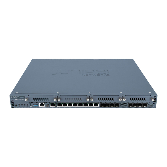
Page 24: Figure 1: Srx340 Services Gateway Front Panel
SRX340 Services Gateway Hardware Guide Figure 1: SRX340 Services Gateway Front Panel Table 3 on page 6 provides details about the front panel components. Table 3: SRX340 Services Gateway Front Panel Components Callout Component Description Reset Config button Returns the services gateway to the rescue configuration or the factory-default configuration. -
Page 25: Figure 2: Srx340 Services Gateway Front Panel Leds
Chapter 2: Chassis Description Table 3: SRX340 Services Gateway Front Panel Components (continued) Callout Component Description 1 G Ethernet ports Eight Gigabit Ethernet LAN ports (0/0 to 0/7) The Gigabit Ethernet ports have the following characteristics: Use an RJ-45 connector... -
Page 26: Understanding The Srx340 Services Gateway Back Panel
Related SRX340 Services Gateway Chassis Overview on page 5 Documentation Understanding the SRX340 Services Gateway Back Panel on page 8 Understanding the SRX340 Services Gateway Back Panel Figure 3 on page 8 shows the back panel of the SRX340 Services Gateway and Table 5 on page 8 lists the components on the back panel. - Page 27 Chapter 2: Chassis Description Related SRX340 Services Gateway Chassis Overview on page 5 Documentation Understanding the SRX340 Services Gateway Front Panel on page 5 Copyright © 2016, Juniper Networks, Inc.
- Page 28 SRX340 Services Gateway Hardware Guide Copyright © 2016, Juniper Networks, Inc.
-
Page 29: Interface Module Descriptions
CAUTION: The Mini-PIMs are not hot-swappable. You must power off the services gateway before removing or installing Mini-PIMs. The following Mini-PIMs are supported on the SRX340 Services Gateway: 1-Port Serial Mini-Physical Interface Module (SRX-MP-1SERIAL-R) 1-Port T1/E1 Mini-Physical Interface Module (SRX-MP-1T1E1-R) - Page 30 SRX340 Services Gateway Hardware Guide Copyright © 2016, Juniper Networks, Inc.
-
Page 31: Cooling System Description
Understanding the SRX340 Services Gateway Cooling System on page 13 Understanding the SRX340 Services Gateway Cooling System The cooling system for the SRX340 Services Gateway includes four fixed fans. The fans draw air through vents on the front of the chassis and exhaust the air through the back of the chassis. - Page 32 SRX340 Services Gateway Hardware Guide Copyright © 2016, Juniper Networks, Inc.
-
Page 33: Power System Description
Understanding the SRX340 Services Gateway Power Supply on page 15 Understanding the SRX340 Services Gateway Power Supply The SRX340 Services Gateway uses a fixed, internal AC power supply. The power supply distributes the different output voltages to the device components according to their voltage requirements. - Page 34 SRX340 Services Gateway Hardware Guide Copyright © 2016, Juniper Networks, Inc.
-
Page 35: Site Planning And Specifications
Site Planning and Specifications Planning and Preparing the Site on page 19 Rack Requirements on page 25 Cabinet Requirements on page 31 Power Requirements and Specifications on page 33 Cable Specifications and Pinouts on page 37 Copyright © 2016, Juniper Networks, Inc. - Page 36 SRX340 Services Gateway Hardware Guide Copyright © 2016, Juniper Networks, Inc.
-
Page 37: Planning And Preparing The Site
SRX340 Services Gateway Environmental Specifications on page 19 Site Preparation Checklist for the SRX340 Services Gateway on page 20 General Site Installation Guidelines for the SRX340 Services Gateway on page 22 SRX340 Services Gateway Physical Specifications Table 6 on page 19 lists the physical specifications for the services gateway. -
Page 38: Site Preparation Checklist For The Srx340 Services Gateway
SRX340 Services Gateway Hardware Guide Table 7: Environmental Specifications for the SRX340 Services Gateway (continued) Description Value Relative humidity 5% to 95%, noncondensing Temperature Operational temperature—32° F (0° C) to 104° F (40° C) Nonoperational temperature—4° F (-20° C) to 158° F (70° C) - Page 39 Chapter 6: Planning and Preparing the Site Table 8: Site Preparation Checklist for SRX340 Services Gateway Installation (continued) Additional Item or Task Information Performed By Date Notes Locate sites for “Connecting the connection of system SRX340 grounding. Services Gateway Grounding Cable”...
-
Page 40: General Site Installation Guidelines For The Srx340 Services Gateway
Plan the cable routing and management. Related General Site Installation Guidelines for the SRX340 Services Gateway on page 22 Documentation General Site Installation Guidelines for the SRX340 Services Gateway The following precautions help you plan an acceptable operating environment for your... - Page 41 Ensure that a blank Mini-PIM panel is installed in the empty slot to prevent any interruption or reduction in the flow of air across internal components. Related Site Preparation Checklist for the SRX340 Services Gateway on page 20 Documentation Copyright © 2016, Juniper Networks, Inc.
- Page 42 SRX340 Services Gateway Hardware Guide Copyright © 2016, Juniper Networks, Inc.
-
Page 43: Rack Requirements
SRX340 Services Gateway Rack-Mounting Requirements and Warnings on page 25 SRX340 Services Gateway Rack Size and Strength Requirements on page 29 SRX340 Services Gateway Spacing of Mounting Brackets and Flange Holes on page 29 SRX340 Services Gateway Clearance Requirements for Airflow and Hardware... - Page 44 Les directives ci-dessous sont destinées à assurer la protection du personnel: Le rack sur lequel est monté le Juniper Networks services gateway doit être fixé à la structure du bâtiment. Si cette unité constitue la seule unité montée en casier, elle doit être placée dans le bas.
- Page 45 Le seguenti direttive vengono fornite per garantire la sicurezza personale: Il Juniper Networks services gateway deve essere installato in un telaio, il quale deve essere fissato alla struttura dell'edificio. Questa unità deve venire montata sul fondo del supporto, se si tratta dell'unica unità...
- Page 46 Om ställningen är försedd med stabiliseringsdon skall dessa monteras fast innan enheten installeras eller underhålls på ställningen. Related SRX340 Services Gateway Rack Size and Strength Requirements on page 29 Documentation Copyright © 2016, Juniper Networks, Inc.
-
Page 47: Srx340 Services Gateway Rack Size And Strength Requirements
Chapter 7: Rack Requirements SRX340 Services Gateway Spacing of Mounting Brackets and Flange Holes on page 29 SRX340 Services Gateway Clearance Requirements for Airflow and Hardware Maintenance on page 30 SRX340 Services Gateway Rack Size and Strength Requirements When installing the services gateway in a rack, you must ensure that the rack complies with a 1U (19 in. -
Page 48: Srx340 Services Gateway Clearance Requirements For Airflow And Hardware
SRX340 Services Gateway Clearance Requirements for Airflow and Hardware Maintenance When planning the installation site for the SRX340 Services Gateway, you need to allow sufficient clearance around the device. Consider the following: For the operating temperature of the services gateway to be optimal, the airflow around the chassis must be unrestricted. -
Page 49: Cabinet Requirements
SRX340 Services Gateway Cabinet Airflow Requirements on page 31 SRX340 Services Gateway Cabinet Size and Clearance Requirements You can install the SRX340 Services Gateway in a 19 in. (48.7 cm) cabinet as defined in Cabinets, Racks, Panels, and Associated Equipment (document number EIA-310-D) published by the Electronic Industries Alliance ( http://www.ecaus.org/eia/site/index.html... - Page 50 Route and dress all cables to minimize the blockage of airflow to and from the chassis. Related SRX340 Services Gateway Cabinet Size and Clearance Requirements on page 31 Documentation Copyright © 2016, Juniper Networks, Inc.
-
Page 51: Power Requirements And Specifications
CHAPTER 9 Power Requirements and Specifications SRX340 Services Gateway Electrical Wiring Guidelines on page 33 SRX340 Services Gateway Power Specifications and Requirements on page 34 SRX340 Services Gateway Supported AC Power Cords on page 35 SRX340 Services Gateway Electrical Wiring Guidelines... -
Page 52: Srx340 Services Gateway Power Specifications And Requirements
SRX340 Services Gateway Supported AC Power Cords on page 35 General Electrical Safety Guidelines and Warnings on page 121 SRX340 Services Gateway Power Specifications and Requirements The AC power system electrical specifications for the SRX340 Services Gateway are listed in Table 10 on page... -
Page 53: Srx340 Services Gateway Supported Ac Power Cords
Related SRX340 Services Gateway Electrical Wiring Guidelines on page 33 Documentation SRX340 Services Gateway Supported AC Power Cords on page 35 SRX340 Services Gateway Supported AC Power Cords WARNING: The AC power cord for the services gateway is intended for use with the services gateway only and not for any other use. - Page 54 SRX340 Services Gateway Hardware Guide Related SRX340 Services Gateway Electrical Wiring Guidelines on page 33 Documentation SRX340 Services Gateway Power Specifications and Requirements on page 34 Copyright © 2016, Juniper Networks, Inc.
-
Page 55: Cable Specifications And Pinouts
CHAPTER 10 Cable Specifications and Pinouts RJ-45 Connector Pinouts for the SRX340 Services Gateway Ethernet Port on page 37 RJ-45 Connector Pinouts for the SRX340 Services Gateway Console Port on page 37 Mini-USB Connector Pinouts for the SRX340 Services Gateway Console Port on page 38... -
Page 56: Mini-Usb Connector Pinouts For The Srx340 Services Gateway Console
Mini-USB Connector Pinouts for the SRX340 Services Gateway Console Port on page 38 Mini-USB Connector Pinouts for the SRX340 Services Gateway Console Port The SRX340 Services Gateway has two console ports: an RJ-45 Ethernet port and a mini-USB Type-B port. If your management device (laptop or PC) does not have a DB-9... -
Page 57: Cable Specifications And Pinouts
Black Ground Related RJ-45 Connector Pinouts for the SRX340 Services Gateway Ethernet Port on page 37 Documentation RJ-45 Connector Pinouts for the SRX340 Services Gateway Console Port on page 37 Copyright © 2016, Juniper Networks, Inc. - Page 58 SRX340 Services Gateway Hardware Guide Copyright © 2016, Juniper Networks, Inc.
-
Page 59: Initial Installation And Configuration
Unpacking the SRX340 Services Gateway on page 45 Installing the Rack Mounting Hardware on page 49 Installing the SRX340 Services Gateway in a Rack on page 51 Connecting the SRX340 Services Gateway to Ground on page 53 Connecting the SRX340 Services Gateway to External Devices on page 57... - Page 60 SRX340 Services Gateway Hardware Guide Copyright © 2016, Juniper Networks, Inc.
-
Page 61: Installation Overview
CHAPTER 11 Installation Overview SRX340 Services Gateway Installation Overview on page 43 Required Tools and Parts for Installing the SRX340 Services Gateway on page 43 SRX340 Services Gateway Autoinstallation Overview on page 44 SRX340 Services Gateway Installation Overview After you have prepared the site for installation and unpacked the SRX340 Services Gateway, you are ready to install the device. -
Page 62: Srx340 Services Gateway Autoinstallation Overview
Installation and Upgrade Guide for Security Devices Network Monitoring and Troubleshooting Guide for Security Devices Related SRX340 Services Gateway Installation Overview on page 43 Documentation Required Tools and Parts for Installing the SRX340 Services Gateway on page 43 Copyright © 2016, Juniper Networks, Inc. -
Page 63: Unpacking The Srx340 Services Gateway
Phillips (+) screwdriver, number 2 Blank panels to cover any slots not occupied by a component The SRX340 Services Gateway is shipped in a cardboard carton and secured with foam packing material. The carton also contains an accessory box and quick start instructions. -
Page 64: Verifying Parts Received With The Srx340 Services Gateway
Table 15: Parts List for a Fully Configured SRX340 Services Gateway Component Quantity 1U SRX340 Services Gateway chassis with 4 Mini-PIM slots, 8 1 G Ethernet ports, and 8 Gigabit Ethernet SFP ports (includes blank covers for Mini-PIM slots). Front-mount and mid-mount rack-mount kit... - Page 65 Chapter 12: Unpacking the SRX340 Services Gateway Related Preparing the SRX340 Services Gateway for Rack-Mount Installation on page 49 Documentation Copyright © 2016, Juniper Networks, Inc.
- Page 66 SRX340 Services Gateway Hardware Guide Copyright © 2016, Juniper Networks, Inc.
-
Page 67: Installing The Rack Mounting Hardware
Documentation Connecting the SRX340 Services Gateway to the Building Structure Always secure the rack in which you are installing the SRX340 High Memory Services Gateway to the structure of the building. If your geographical area is subject to Copyright © 2016, Juniper Networks, Inc. - Page 68 For maximum stability, also secure the rack to ceiling brackets. Related Installing the SRX340 Services Gateway in a Rack on page 51 Documentation Preparing the SRX340 Services Gateway for Rack-Mount Installation on page 49...
-
Page 69: Installing The Srx340 Services Gateway In A Rack
Installing the SRX340 Services Gateway in a Rack on page 51 Installing the SRX340 Services Gateway in a Rack You can front-mount the SRX340 Services Gateway in a rack. Many types of racks are acceptable, including four-post (telco) racks, enclosed cabinets, and open-frame racks. -
Page 70: Figure 7: Installing The Rack Mount Brackets (Center Mount Position)
Related Connecting the SRX340 Services Gateway Grounding Cable on page 54 Documentation Connecting the SRX340 Services Gateway to an AC Power Supply on page 59 Copyright © 2016, Juniper Networks, Inc. -
Page 71: Connecting The Srx340 Services Gateway To Ground
CHAPTER 15 Connecting the SRX340 Services Gateway to Ground Required Tools and Parts for Grounding the SRX340 Services Gateway on page 53 SRX340 Services Gateway Grounding Specifications on page 53 Connecting the SRX340 Services Gateway Grounding Cable on page 54... -
Page 72: Connecting The Srx340 Services Gateway Grounding Cable
Grounding lug Ring-type, vinyl-insulated TV14-6R lug or equivalent Related Required Tools and Parts for Grounding the SRX340 Services Gateway on page 53 Documentation Connecting the SRX340 Services Gateway Grounding Cable on page 54 Connecting the SRX340 Services Gateway Grounding Cable... -
Page 73: Figure 9: Connecting The Grounding Cable To The Srx340 Services Gateway
NOTE: The device should be permanently connected to ground during operation. Related Required Tools and Parts for Grounding the SRX340 Services Gateway on page 53 Documentation SRX340 Services Gateway Grounding Specifications on page 53 Copyright © 2016, Juniper Networks, Inc. - Page 74 SRX340 Services Gateway Hardware Guide Copyright © 2016, Juniper Networks, Inc.
-
Page 75: Connecting The Srx340 Services Gateway To External Devices
Connecting the Dial-Up Modem to the Console Port on the SRX340 Services Gateway on page 57 Connecting to the SRX340 Services Gateway CLI Using a Dial-Up Modem on page 58 Connecting the Dial-Up Modem to the Console Port on the SRX340 Services Gateway To connect the dial-up modem to the console port on the services gateway: Turn off power to the services gateway. -
Page 76: Connecting To The Srx340 Services Gateway Cli Using A Dial-Up Modem
Log in as the root user. No password is required at initial connection, but you must assign a root password before committing any configuration settings. Related Connecting the Dial-Up Modem to the Console Port on the SRX340 Services Gateway Documentation on page 57... -
Page 77: Providing Power To The Srx340 Services Gateway
CHAPTER 17 Providing Power to the SRX340 Services Gateway Connecting the SRX340 Services Gateway to an AC Power Supply on page 59 Powering On the SRX340 Services Gateway on page 60 Powering Off the SRX340 Services Gateway on page 60... -
Page 78: Powering On The Srx340 Services Gateway
CLI command. request system power-off Related Connecting the SRX340 Services Gateway to an AC Power Supply on page 59 Documentation Powering Off the SRX340 Services Gateway on page 60 Powering Off the SRX340 Services Gateway You can power off the services gateway in one of the following ways:... - Page 79 You can use the request system reboot CLI command to schedule a reboot. Related Connecting the SRX340 Services Gateway to an AC Power Supply on page 59 Documentation Powering On the SRX340 Services Gateway on page 60 Copyright © 2016, Juniper Networks, Inc.
- Page 80 SRX340 Services Gateway Hardware Guide Copyright © 2016, Juniper Networks, Inc.
-
Page 81: Performing The Initial Configuration
Viewing SRX340 Services Gateway Factory-Default Settings on page 64 Accessing J-Web on the SRX340 Services Gateway on page 66 Configuring the SRX340 Services Gateway Using the J-Web Setup Wizard on page 67 Accessing the CLI on the SRX340 Services Gateway on page 69... -
Page 82: Understanding Srx340 Services Gateway Factory-Default Settings
Viewing SRX340 Services Gateway Factory-Default Settings on page 64 Accessing J-Web on the SRX340 Services Gateway on page 66 Configuring the SRX340 Services Gateway Using the J-Web Setup Wizard on page 67 Accessing the CLI on the SRX340 Services Gateway on page 69... - Page 83 View the required default config file. % vi config filename Copyright © 2016, Juniper Networks, Inc.
-
Page 84: Accessing J-Web On The Srx340 Services Gateway
Understanding SRX340 Services Gateway Factory-Default Settings on page 64 Accessing J-Web on the SRX340 Services Gateway on page 66 Configuring the SRX340 Services Gateway Using the J-Web Setup Wizard on page 67 Accessing the CLI on the SRX340 Services Gateway on page 69... -
Page 85: Configuring The Srx340 Services Gateway Using The J-Web Setup Wizard
Understanding SRX340 Services Gateway Factory-Default Settings on page 64 Viewing SRX340 Services Gateway Factory-Default Settings on page 64 Configuring the SRX340 Services Gateway Using the J-Web Setup Wizard on page 67 Accessing the CLI on the SRX340 Services Gateway on page 69... -
Page 86: About The Default Setup Mode
J-Web interface, or by using the CLI. See the for step-by-step instructions on How to Set Up Your SRX340 Services Gateway how to configure your services gateway in the Default Setup mode. About the Guided Setup Mode If you choose the Guided Setup mode, the wizard guides you through configuring your services gateway in a custom security configuration. -
Page 87: Accessing The Cli On The Srx340 Services Gateway
Accessing J-Web on the SRX340 Services Gateway on page 66 Accessing the CLI on the SRX340 Services Gateway on page 69 Connecting to the SRX340 Services Gateway from the CLI Remotely on page 71 Configuring the SRX340 Services Gateway Using the CLI on page 71... -
Page 88: Figure 12: Connecting To The Console Port On The Srx340 Services Gateway
To use the USB console port, you must download a USB driver to the management device from http://www.juniper.net/support/downloads/group/?f=junos Figure 12: Connecting to the Console Port on the SRX340 Services Gateway Start your asynchronous terminal emulation application (such as Microsoft Windows HyperTerminal) and select the appropriate COM port to use (for example, COM1). -
Page 89: Connecting To The Srx340 Services Gateway From The Cli Remotely
Chapter 18: Performing the Initial Configuration Configuring the SRX340 Services Gateway Using the J-Web Setup Wizard on page 67 Connecting to the SRX340 Services Gateway from the CLI Remotely on page 71 Configuring the SRX340 Services Gateway Using the CLI on page 71... - Page 90 SRX340 Services Gateway Hardware Guide [edit] root# set system login user admin class super-user authentication plain-text-password New password: password Retype new password: password Commit the configuration to activate it on the services gateway. [edit] root# commit Log in as the administrative user you configured in Step 6.
- Page 91 Viewing SRX340 Services Gateway Factory-Default Settings on page 64 Accessing J-Web on the SRX340 Services Gateway on page 66 Configuring the SRX340 Services Gateway Using the J-Web Setup Wizard on page 67 Accessing the CLI on the SRX340 Services Gateway on page 69 Connecting to the SRX340 Services Gateway from the CLI Remotely on page 71 Copyright ©...
- Page 92 SRX340 Services Gateway Hardware Guide Copyright © 2016, Juniper Networks, Inc.
-
Page 93: Maintaining And Troubleshooting Components
PART 4 Maintaining and Troubleshooting Components Maintaining Components on page 77 Troubleshooting Components on page 79 Copyright © 2016, Juniper Networks, Inc. - Page 94 SRX340 Services Gateway Hardware Guide Copyright © 2016, Juniper Networks, Inc.
-
Page 95: Maintaining Components
CHAPTER 19 Maintaining Components Required Tools and Parts for Maintaining the SRX340 Services Gateway Hardware Components on page 77 Routine Maintenance Procedures for the SRX340 Services Gateway on page 77 Maintaining the SRX340 Services Gateway Cooling System Components on page 78... -
Page 96: Maintaining The Srx340 Services Gateway Cooling System Components
SRX340 Services Gateway Hardware Guide Related Required Tools and Parts for Maintaining the SRX340 Services Gateway Hardware Documentation Components on page 77 Maintaining the SRX340 Services Gateway Cooling System Components on page 78 Maintaining the SRX340 Services Gateway Power Supply on page 78... -
Page 97: Troubleshooting Components
Gateway on page 80 Troubleshooting the Power System on the SRX340 Services Gateway on page 81 Using the RESET CONFIG Button on the SRX340 Services Gateway on page 82 Changing the RESET CONFIG Button Behavior on the SRX340 Services Gateway on page 83... -
Page 98: Troubleshooting Chassis And Interface Alarm Messages On The Srx340 Services
SRX340 Services Gateway Hardware Guide Troubleshooting Chassis and Interface Alarm Messages on the SRX340 Services Gateway When the services gateway detects an alarm condition, the alarm LED on the front panel turns red or amber as appropriate. To view a more detailed description of the alarm cause, issue the CLI command. -
Page 99: Troubleshooting The Power System On The Srx340 Services Gateway
Documentation Troubleshooting the Power System on the SRX340 Services Gateway on page 81 Using the RESET CONFIG Button on the SRX340 Services Gateway on page 82 Changing the RESET CONFIG Button Behavior on the SRX340 Services Gateway on page 83... -
Page 100: Using The Reset Config Button On The Srx340 Services Gateway
Troubleshooting Chassis and Interface Alarm Messages on the SRX340 Services Gateway on page 80 Using the RESET CONFIG Button on the SRX340 Services Gateway on page 82 Changing the RESET CONFIG Button Behavior on the SRX340 Services Gateway on page 83... -
Page 101: Gateway
Troubleshooting Chassis and Interface Alarm Messages on the SRX340 Services Gateway on page 80 Troubleshooting the Power System on the SRX340 Services Gateway on page 81 Using the RESET CONFIG Button on the SRX340 Services Gateway on page 82 Copyright © 2016, Juniper Networks, Inc. - Page 102 SRX340 Services Gateway Hardware Guide Copyright © 2016, Juniper Networks, Inc.
-
Page 103: Replacing Components
PART 5 Replacing Components Overview of Replacing Components on page 87 Replacing Interface Modules on page 89 Contacting Customer Support and Returning Components on page 91 Copyright © 2016, Juniper Networks, Inc. - Page 104 SRX340 Services Gateway Hardware Guide Copyright © 2016, Juniper Networks, Inc.
-
Page 105: Overview Of Replacing Components
SRX340 Services Gateway Field Replaceable Units Overview Field-replaceable units (FRUs) are components that you can replace at your site. The Mini-Physical Interface Module (MPIM) is the only FRU on the SRX340 Services Gateway. The Mini-PIMs are not hot-swappable. You must power off the services gateway before removing or installing Mini-PIMs. - Page 106 SRX340 Services Gateway Hardware Guide Copyright © 2016, Juniper Networks, Inc.
-
Page 107: Replacing Interface Modules
CHAPTER 22 Replacing Interface Modules Replacing Mini-Physical Interface Modules in the SRX340 Services Gateway on page 89 Replacing Mini-Physical Interface Modules in the SRX340 Services Gateway The Mini-PIMs available on the SRX340 Services Gateway are not hot-swappable. You need to power off the device before removing or installing Mini-PIMs. For information on replacing Mini-PIMs, see the SRX300 Series and SRX550 High Memory Services Gateway Interface Modules Reference. - Page 108 SRX340 Services Gateway Hardware Guide Copyright © 2016, Juniper Networks, Inc.
-
Page 109: Contacting Customer Support And Returning Components
Contacting Customer Support Once you have located the serial numbers of the device or component, you can return the device or component for repair or replacement. For this, you need to contact Juniper Networks Technical Assistance Center (JTAC). You can contact JTAC 24 hours a day, 7 days a week, using any of the following methods: On the Web: Using the Case Manager link at http://www.juniper.net/support/... -
Page 110: Returning A Srx340 Services Gateway Component To Juniper Networks
Packing SRX340 Services Gateway Components for Shipment on page 96 Returning a SRX340 Services Gateway Component to Juniper Networks To return an SRX340 Services Gateway or component to Juniper Networks for repair or replacement: Determine the part number and serial number of the services gateway or component. -
Page 111: Locating The Srx340 Services Gateway Chassis Serial Number And Agency
Locating the SRX340 Services Gateway Mini-Physical Interface Module Serial Number Label on page 93 Listing the SRX340 Services Gateway Component Details with the CLI on page 93 Information You Might Need to Supply to JTAC on page 94 Required Tools and Parts for Packing the SRX340 Services Gateway on page 95... -
Page 112: Information You Might Need To Supply To Jtac
SRX340 Services Gateway Hardware Guide To list all of the SRX340 Services Gateway components and their serial numbers, enter the following command: user@host> show chassis hardware Hardware inventory: Item Version Part number Serial number Description Chassis CZ3615AN0003 SRX340 Routing Engine... -
Page 113: Required Tools And Parts For Packing The Srx340 Services Gateway
Packing SRX340 Services Gateway Components for Shipment on page 96 Required Tools and Parts for Packing the SRX340 Services Gateway To remove the components from the SRX340 Services Gateway or to remove the services gateway from a rack, you need the following tools and parts:... -
Page 114: Packing Srx340 Services Gateway Components For Shipment
Locating the SRX340 Services Gateway Mini-Physical Interface Module Serial Number Label on page 93 Listing the SRX340 Services Gateway Component Details with the CLI on page 93 Information You Might Need to Supply to JTAC on page 94 Required Tools and Parts for Packing the SRX340 Services Gateway on page 95... - Page 115 Locating the SRX340 Services Gateway Mini-Physical Interface Module Serial Number Label on page 93 Listing the SRX340 Services Gateway Component Details with the CLI on page 93 Information You Might Need to Supply to JTAC on page 94 Required Tools and Parts for Packing the SRX340 Services Gateway on page 95 Packing the SRX340 Services Gateway for Shipment on page 95 Copyright ©...
- Page 116 SRX340 Services Gateway Hardware Guide Copyright © 2016, Juniper Networks, Inc.
-
Page 117: Part 6 Safety And Regulatory Compliance Information
Laser and LED Safety Guidelines and Warnings on page 111 Maintenance and Operational Safety Guidelines and Warnings on page 115 Electrical Safety Guidelines and Warnings on page 121 Agency Approvals and Regulatory Compliance Information on page 125 Copyright © 2016, Juniper Networks, Inc. - Page 118 SRX340 Services Gateway Hardware Guide Copyright © 2016, Juniper Networks, Inc.
-
Page 119: General Safety Guidelines And Warnings
Preventing Electrostatic Discharge Damage to the SRX340 Services Gateway on page 107 SRX340 Services Gateway Definition of Safety Warning Levels This topic defines the following four levels of safety warnings used in Juniper Networks technical publications: NOTE: You might find this information helpful in a particular situation or might otherwise overlook it. - Page 120 SRX340 Services Gateway Hardware Guide Waarschuwing Dit waarschuwingssymbool betekent gevaar. U verkeert in een situatie die lichamelijk letsel kan veroorzaken. Voordat u aan enige apparatuur gaat werken, dient u zich bewust te zijn van de bij elektrische schakelingen betrokken risico's en dient u op de hoogte te zijn van standaard maatregelen om ongelukken te voorkomen.
-
Page 121: Srx340 Services Gateway General Safety Guidelines And Warnings
Chapter 24: General Safety Guidelines and Warnings Related SRX340 Services Gateway General Safety Guidelines and Warnings on page 103 Documentation SRX340 Services Gateway Safety Requirements, Warnings, and Guidelines on page 104 Restricted Access Area Warning on page 104 Qualified Personnel Warning on page 106... -
Page 122: Srx340 Services Gateway Safety Requirements, Warnings, And Guidelines
Providing an exhaustive set of guidelines for working with electrical equipment is beyond the scope of this guide. Related SRX340 Services Gateway Definition of Safety Warning Levels on page 101 Documentation SRX340 Services Gateway General Safety Guidelines and Warnings on page 103... - Page 123 Related SRX340 Services Gateway Definition of Safety Warning Levels on page 101 Documentation SRX340 Services Gateway General Safety Guidelines and Warnings on page 103 SRX340 Services Gateway Safety Requirements, Warnings, and Guidelines on page 104...
-
Page 124: Qualified Personnel Warning
Varning! Denna utrustning ska endast installeras och bytas ut av utbildad och kvalificerad personal. Related SRX340 Services Gateway Definition of Safety Warning Levels on page 101 Documentation SRX340 Services Gateway General Safety Guidelines and Warnings on page 103 SRX340 Services Gateway Safety Requirements, Warnings, and Guidelines on page 104... -
Page 125: Gateway
Figure 13: Placing a Component into an Electrostatic Bag Related SRX340 Services Gateway Definition of Safety Warning Levels on page 101 Documentation SRX340 Services Gateway General Safety Guidelines and Warnings on page 103 SRX340 Services Gateway Safety Requirements, Warnings, and Guidelines on page 104... - Page 126 SRX340 Services Gateway Hardware Guide Copyright © 2016, Juniper Networks, Inc.
-
Page 127: Fire Safety Requirements
SRX340 Services Gateway Fire Safety Requirements and Fire Suppression Equipment on page 109 SRX340 Services Gateway Fire Safety Requirements and Fire Suppression Equipment In the event of a fire emergency involving devices and other network equipment, the safety of people is the primary concern. Establish procedures for protecting people in the event of a fire emergency, provide safety training, and properly provision fire control equipment and fire extinguishers. - Page 128 To keep warranties effective, do not use a dry chemical fire extinguisher to control a fire at or near a Juniper Networks services gateway. If a dry chemical fire extinguisher is used, the unit is no longer eligible for coverage under a service agreement.
-
Page 129: Laser And Led Safety Guidelines And Warnings
Related Class 1 Laser Warning on page 112 Documentation Class 1 LED Product Warning on page 112 Laser Beam Warning on page 113 Radiation from Open Port Apertures Warning on page 114 Copyright © 2016, Juniper Networks, Inc. -
Page 130: Class 1 Laser Warning
SRX340 Services Gateway Hardware Guide Class 1 Laser Warning WARNING: Class 1 laser product. Waarschuwing Klasse-1 laser produkt. Varoitus Luokan 1 lasertuote. Attention Produit laser de classe I. Warnung Laserprodukt der Klasse 1. Avvertenza Prodotto laser di Classe 1. Advarsel Laserprodukt av klasse 1. -
Page 131: Laser Beam Warning
Related General Laser Safety Guidelines on page 111 Documentation Class 1 Laser Warning on page 112 Class 1 LED Product Warning on page 112 Radiation from Open Port Apertures Warning on page 114 Copyright © 2016, Juniper Networks, Inc. -
Page 132: Radiation From Open Port Apertures Warning
SRX340 Services Gateway Hardware Guide Radiation from Open Port Apertures Warning WARNING: Because invisible radiation can be emitted from the aperture of the port when no fiber cable is connected, avoid exposure to radiation and do not stare into open apertures. -
Page 133: Maintenance And Operational Safety Guidelines And Warnings
Warnung Bei Einsetzen einer falschen Batterie besteht Explosionsgefahr. Ersetzen Sie die Batterie nur durch den gleichen oder vom Hersteller empfohlenen Batterietyp. Entsorgen Sie die benutzten Batterien nach den Anweisungen des Herstellers. Copyright © 2016, Juniper Networks, Inc. -
Page 134: Lightning Activity Warning
SRX340 Services Gateway Hardware Guide Avvertenza Pericolo di esplosione se la batteria non è installata correttamente. Sostituire solo con una di tipo uguale o equivalente, consigliata dal produttore. Eliminare le batterie usate secondo le istruzioni del produttore. Advarsel Det kan være fare for eksplosjon hvis batteriet skiftes på feil måte. -
Page 135: Jewelry Removal Warning
Warnung Vor der Arbeit an Geräten, die an das Netz angeschlossen sind, jeglichen Schmuck (einschließlich Ringe, Ketten und Uhren) abnehmen. Metallgegenstände erhitzen sich, wenn sie an das Netz und die Erde Copyright © 2016, Juniper Networks, Inc. -
Page 136: Operating Temperature Warning
SRX340 Services Gateway Hardware Guide angeschlossen werden, und können schwere Verbrennungen verursachen oder an die Anschlußklemmen angeschweißt werden. Avvertenza Prima di intervenire su apparecchiature collegate alle linee di alimentazione, togliersi qualsiasi monile (inclusi anelli, collane, braccialetti ed orologi). Gli oggetti metallici si riscaldano quando sono collegati tra punti di alimentazione e massa: possono causare ustioni gravi oppure il metallo può... - Page 137 Chapter 27: Maintenance and Operational Safety Guidelines and Warnings Waarschuwing Om te voorkomen dat welke services gateway van de Juniper Networks services gateway dan ook oververhit raakt, dient u deze niet te bedienen op een plaats waar de maximale aanbevolen ο...
-
Page 138: Product Disposal Warning
SRX340 Services Gateway Hardware Guide inskränks genom att se till att det finns fritt utrymme på minst 15,2 cm omkring ventilationsöppningarna. Related Battery-Handling Warning on page 115 Documentation Lightning Activity Warning on page 116 Jewelry Removal Warning on page 117... -
Page 139: Electrical Safety Guidelines And Warnings
Locate the emergency power-off switch for the room in which you are working so that if an electrical accident occurs, you can quickly turn off the power. Do not work alone if potentially hazardous conditions exist anywhere in your workspace. Copyright © 2016, Juniper Networks, Inc. -
Page 140: Ac Power Electrical Safety Guidelines
SRX340 Services Gateway Hardware Guide Never assume that power is disconnected from a circuit. Always check the circuit before starting to work. Carefully look for possible hazards in your work area, such as moist floors, ungrounded power extension cords, and missing safety grounds. - Page 141 Chapter 28: Electrical Safety Guidelines and Warnings Related In Case of Electrical Accident on page 121 Documentation General Electrical Safety Guidelines and Warnings on page 121 Copyright © 2016, Juniper Networks, Inc.
- Page 142 SRX340 Services Gateway Hardware Guide Copyright © 2016, Juniper Networks, Inc.
-
Page 143: Agency Approvals And Regulatory Compliance Information
Agency Approvals and Regulatory Compliance Information SRX340 Services Gateway Agency Approvals on page 125 SRX340 Services Gateway Acoustic Noise Compliance Statements on page 126 SRX340 Services Gateway EMC Requirements on page 127 SRX340 Services Gateway Agency Approvals The services gateway complies with the following standards: Safety CAN/CSA-C22.2 No.60950-1 (2007) Information Technology Equipment... -
Page 144: Srx340 Services Gateway Acoustic Noise Compliance Statements
Reduction of Hazardous Substances (ROHS) 6 Telco Common Language Equipment Identifier (CLEI) code Related SRX340 Services Gateway Acoustic Noise Compliance Statements on page 126 Documentation SRX340 Services Gateway EMC Requirements on page 127 SRX340 Services Gateway Acoustic Noise Compliance Statements The maximum emitted sound pressure level is 70 dB(A) or less per EN ISO 7779. -
Page 145: Srx340 Services Gateway Emc Requirements
Chapter 29: Agency Approvals and Regulatory Compliance Information SRX340 Services Gateway EMC Requirements Canada This Class A digital apparatus complies with Canadian ICES-003. Cet appareil numérique de la classe A est conforme à la norme NMB-003 du Canada. European Community This is a Class A product. - Page 146 SRX340 Services Gateway Hardware Guide Related SRX340 Services Gateway Agency Approvals on page 125 Documentation SRX340 Services Gateway Acoustic Noise Compliance Statements on page 126 Copyright © 2016, Juniper Networks, Inc.
- Page 147 PART 7 Index Index on page 131 Copyright © 2016, Juniper Networks, Inc.
- Page 148 SRX340 Services Gateway Hardware Guide Copyright © 2016, Juniper Networks, Inc.
-
Page 149: Index
1 laser warning..............112 class 1 LED warning..............112 jewelry removal warning............117 comments, in configuration statements......xv JTAC....................91 compliance statement, acoustic noise......126 Juniper Technical Assistance Center See JTAC compliance statements for EMC requirements Canada................127 European Community..........127 laser beam warning...............113 Hebrew................127 laser safety guidelines............111 Japan..................127... - Page 150 SRX340 Services Gateway Hardware Guide operating temperature warning........118 technical support overview, installation of services gateway....43 contacting JTAC..............xvi tools required for packing................95 packing services gateway components for shipment.........96 required tools and parts..........95 warning parentheses, in syntax descriptions.........xv electrical safety guidelines.........121 parts...
Need help?
Do you have a question about the SRX340 and is the answer not in the manual?
Questions and answers