Table of Contents
Advertisement
Quick Links
Overview
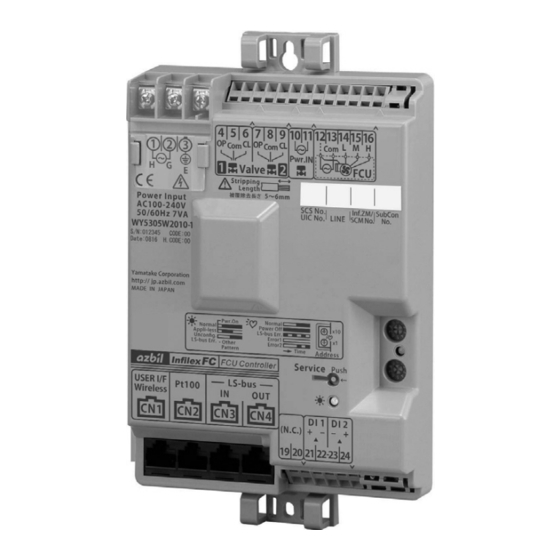
Infilex FC (Infilex: named for "Infinity" and "Flexible") Model
WY5305 provides digital control of fan coil units (FCU). In
addition to FCU start/stop operation, valve control, and fan
speed changeover, Infilex FC provides advanced controls
such as setback and interlock operations with outdoor air
handling unit (OAHU).
Infilex FC can interface with user terminals to allow the end
users to operate the FCU.
Infilex FC can directly communicate with the center unit of an
integrated Building Management System (BMS), Azbil
Corporation's savic-net
series. That is, scheduled operation,
operating status, and temperature measurement of the FCU
can be centrally monitored and controlled.
Features
Compact size
Small sized body fits inside an FCU.
Easy installation
Connectors facilitate wiring installation.
Two kinds of FCU control
Valve ON/OFF control and valve proportional control for
FCU are available.
Various connectable terminals
In addition to the temperature sensor, digital and analog
user terminals can be connected to the Infilex FC.
L
M
certified product
ON
ARK
FCU control network is configured with LonTalk
protocol.
Infilex FC (Model WY5305WXXXX-1) is
L
M
(version 3.4) certified and thus interoperable
ON
ARK
integrated in the L
W
ON
CE Marking certified product
Infilex FC Models WY5305W1000, WY5305W2010
conform to all the applicable standards of CE Marking
(Class A).
Azbil Corporation's controller Infilex series: Infilex is named for "Infinity" and "Flexible".
Infilex
Fan Coil Unit Controller
system.
ORKS
FC
Model Numbers
WY5305
W
1
2
0
Note:
Base model number is available with the following suffix numbers:
W1000-1, W1000-0, W2010-1, W2010-0
© 2005–2018 Azbil Corporation All Rights Reserved.
1
Specifications/Instructions
Base model number
Power:
100 V AC to 240 V AC
Valve ON/OFF control
Valve proportional control
Fixed
0
Without DI (digital input)
With DI 2 pts.
1
0
Fixed
-0
LONMARK
uncertified
-1
LONMARK
certified
AB-6569
Advertisement
Table of Contents

Related Manuals for Azbil Infilex FC


Summary of Contents for Azbil Infilex FC
- Page 1 Infilex FC provides advanced controls such as setback and interlock operations with outdoor air handling unit (OAHU). Infilex FC can interface with user terminals to allow the end users to operate the FCU. Infilex FC can directly communicate with the center unit of an integrated Building Management System (BMS), Azbil ...
-
Page 2: Safety Precautions
• Aeronautical/aerospace machines For system design, application design, instructions for use, or product applications, please contact Azbil Corporation. Azbil Corporation bears no responsibility for any result, or lack of result, deriving from the customer's use of the product. Warnings and Cautions ... - Page 3 Infilex FC, Infilex VC, and Infilex SC can directly connected to LC-bus with their network variables. One Neoplate (analog user terminal) or two Neopanel (digital user terminal) can be connected t to one Infilex FC. Neopanel or Neoplate can share the Infilex FC with a temperature sensor.
-
Page 4: Basic Specifications
1 For connector connection, use Stewart Connector’s Plug: Model 940-SP-3088R. This plug is also available at Azbil Corporation. (Part No. DY7207A0100, 100 pieces/set) 2 LAN cable compliant with EIA/TIA-568 Category 3 or over (0.5 mm 4 poles) is required. - Page 5 AB-6569 Dimensions <Valve ON/OFF control type> Figure 2. Dimensions (mm): Model WY5305W1000 <Valve proportional control type> Figure 3. Dimensions (mm): Model WY5305W2010...
-
Page 6: Wiring Connection
Note: Order of valve open/close operation can be set with parameters. IMPORTANT: Power for the valve actuators is supplied from FCU via Infilex FC. Since the actuator power supply cannot be separated from the FCU, the valves, unless the valve type is spring-return, will not be fully closed (in 0%... - Page 7 Note: Order of valve open/close operation can be set with parameters. IMPORTANT: If Infilex FC is used in a 24-hour operation system, be sure to fully close/open the valves (in 0 %/100 % position) at least once a day. (The valves can be forcibly opened/closed with parameter setting.)
-
Page 8: Installation And Wiring
AB-6569 Installation and Wiring 3) To mount Infilex FC on a threaded rod (9 mm) in the ceiling, use two cable ties. Put a cable tie through two 1) Open the mounting hole. holes on the bilateral sides of the M4 screw hole on a Open two holes for M4 screws with a 139 mm ... -
Page 9: Precautions For Installation
Leave clearance as shown in Figs. 11 and 12. Vertically (for clamp release) on the terminal blocks located on the mount the Infilex FC (lengthwise). Be sure to mount it in upper and lower side of the front surface. a location where parts identification indication on the 2. - Page 10 (See ‘B’ in Fig. 13.) If the Infilex FC is mounted with its 5) Lightly pull the wires connected to make sure it is completely front surface facing the vertical direction (upwards), dust held by clamp.
- Page 11 Cable stopper Insert. and a modular jack (female). Modular jacks are provided on Infilex FC, and modular plugs will be crimped on LAN cables LAN cable as requires. Refer to the following procedure for crimping the modular plugs on the LAN cables and connecting them to the 10 ...
-
Page 12: Parts Description
Adaptor for connecting to a Pt100 sensor: Modular continuity tester: Connects temperature sensor to Infilex FC with modular Checks continuity of LAN cables with modular plugs connection. crimped on. Figure 21. Adaptor for connecting to a PT100 sensor: Part No. - Page 13 AB-6569 Terminator For LonTalk protocol, terminator is required to ensure the communication reliability. For bus topology, a terminator is connected at each end of the devices on the bus (= 2 terminators for bus topology). For free topology, a terminator is connected at any end of the devices on the bus (= 1 terminator for free topology) throughout the whole system.
-
Page 14: Software Details
AB-6569 Software Details Functions with the symbol * are available when Infilex FC is combined with Infilex ZM, other controllers, and the center unit in a BMS. (1/3) Item Function Description Remarks Operation (common to FCU start/stop FCU is turned on/off with the center unit, DI, or a... - Page 15 (Not all the items above are required to centrally monitor or control.) Group monitoring* Multiple Infilex FC are divided into groups, and with All the Infilex FC connected from a the center unit, the following items can be monitored certain Infilex ZM can be divided into up and controlled per grouped Infilex FC: to 25 groups.
- Page 16 AB-6569 (3/3) Item Function Description Remarks External contact input Alarm input Input value of DI (digital input) 1 is reflected in the Alarm input is applicable only to Models (DI) alarm point. When the contact of DI 1 is open, NML WY5305W2010.
-
Page 17: Address Setting
For setting the address, use a small Phillips screwdriver to LED indication turn the dial. After the power is applied to Infilex FC, check that the status Parameter setting indicator LED blinks in approx. 10 seconds. If it stays ON, Infilex FC is in an abnormal status. - Page 18 AB-6569 Network Interface between Infilex FC and Other Devices Program ID XX:00:5F:50:14:03:04:XX Documentation &3.4@0Node,8020FCUControl;Inf-FC WY5305 Program ID revision 90:00:5F:50:14:03:04 WY5305***** (rev. 01 - 02) WY5305***** (rev. 03) WY5305*****-0 80:00:5F:50:14:03:04 WY5305*****-1 (rev.04 -) Object details (continued to the following page) Infilex FC controller object ...
- Page 19 AB-6569 Controller object Hardware Outputs FCU Device object Type #8020 nviSpaceTemp nvoHeatOutput SNVT_temp_p SNVT_lev_precent Mandatory Network nviSetPoint nvoCoolOutput Variables SNVT_temp_p SNVT_lev_percent nvoFanSpeed SNVT_switch nv15 nviFanSpeedCmd nvoSpaceTemp SNVT_switch SNVT_temp_p nv16 nviOccCmd Optional nvoEffectSetPt Network SNVT_Occupancy SNVT_temp_p Variables nv19 nviApplicMode nvoOccCmd SNVT_hvac_mode SNVT_occupancy nv21...
-
Page 20: Network Variables
AB-6569 Network variables Node object Input network variables (according to L Functional Profile: Node object) Variable name SNVT name Valid range Default value Description nviRequest SNVT_obj_request Object request nviTimeSet SNVT_time_stamp Time setting... - Page 21 AB-6569 Controller object Input network variables (according to L Functional Profile: FCU Controller) Variable name SNVT name Valid range Default value Description -10.00 to 50.00 C nviSpaceTemp SNVT_temp_p 327.67 Space temperature input (external space temperature sensor) 10.00 to 35.00 C ...
- Page 22 AB-6569 User-defined network variables User-defined input network variables Variable name SNVT name Valid range Default value Description -99.9 to 99.9 C nviOutdoorTemp SNVT_temp_p 327.67 Outdoor temperature input nviRainState SNVT_switch Wet weather indication input ...
- Page 23 AB-6569 This blank page was added for page layout purposes.
- Page 24 Pollution degree 2 RoHSD: EN 50581 Infilex, Microstat, Neopanel, PARAMATRIX, and savic-net are trademarks or registered trademarks of Azbil Corporation in Japan or in other countries. BACnet is a registered trademark of American Society of Heating, Refrigerating and Air-Conditioning Engineers (ASHRAE).
Need help?
Do you have a question about the Infilex FC and is the answer not in the manual?
Questions and answers