Table of Contents
Advertisement
No. CP-SP-1265E
SDC45/46
Digital Indicating Controller
User's Manual
for
Displays and Settings
Thank you for purchasing an Azbil
Corporation product.
This manual contains information
for ensuring the correct use of this
product. It also provides necessary
information for installation, main-
tenance, and troubleshooting.
This manual should be read by
those who design and maintain
equipment that uses this product.
Be sure to keep this manual nearby
for handy reference.
Advertisement
Table of Contents

Related Manuals for Azbil SDC45


Summary of Contents for Azbil SDC45
- Page 1 No. CP-SP-1265E SDC45/46 Digital Indicating Controller User's Manual Displays and Settings Thank you for purchasing an Azbil Corporation product. This manual contains information for ensuring the correct use of this product. It also provides necessary information for installation, main- tenance, and troubleshooting.
- Page 2 If you should find an error or omission, please contact the azbil Group. In no event is Azbil Corporation liable to anyone for any indirect, special or consequential damages as a result of using this product. © 2007–2018 Azbil Corporation. All Rights Reserved.
- Page 3 The Role of This Manual A total of 5 different manuals are available for the SDC45/46. Read them as necessary for your specific requirements. If a manual you require is not available, contact the azbil Group or its dealer. SDC45/46 Digital Indicating Controller User’s Manual for Displays and Settings Manual No.
- Page 4 The manual describes the software used to make various set- tings for SDC45/46 using a personal computer. Personnel in charge of design or setting of a system using SDC45/46 must thoroughly read this manual. The manual describes installation of the software into a personal computer, operation of the per-...
-
Page 5: Table Of Contents
Contents The Role of This Manual Chapter 1. PRELIMINARIES ■ ■ Names and function of parts ■ ■ Method of key operations Chapter 2. PARA BANK SETTINGS ■ ■ Mode bank ( MODE ■ ■ Loop 1 PID bank ( L 1.PI D ■... - Page 6 Chapter 3. SP/EV BANK SETTINGS ■ ■ SP group selection bank ( SPNO ■ ■ Loop 1 multi-SP bank ( L 1.LSP ■ ■ Loop 2 multi-SP bank ( L2.LSP ■ ■ Loop 1 recipe bank ( L 1.rec ■ ■ Loop 2 recipe bank ( 3-11 L2.rec ■...
-
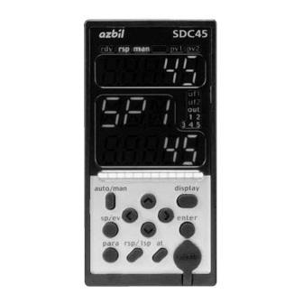
Page 7: Chapter 1. Preliminaries
Lights up in RSP (remote setting input) mode. man: Lights up in MANUAL mode. out1-7: Light up when the output is ON (SDC45: out1-5). Always lit when the output is current or continu- ous voltage. (6) User function indicators: uf1-4: Light under user-assigned conditions (SDC45: uf1, uf2). -
Page 8: Method Of Key Operations
Chapter 1. PRELIMINARIES ■ Method of key operations ● Key operations when setting PARA bank (1) Press the [display] key to return to the operation display. (2) To select a bank, keep the [para] key pressed for 2 s. (3) To display a bank to be set, press the [para] key, [ ] key, or [ ] key. (4) When a desired bank is displayed, press the [enter] key. -
Page 9: Mode Bank ( Mode )
Chapter 2. PARA BANK SETTINGS ■ Mode bank ( MODE Display Loop number Item Settings and descriptions Initial User Remarks (auxiliary display) value setting RUN/READY : RUN mode r---r L. 1. : READY mode AUTO/MANUAL : AUTO mode AUTO A---M L. - Page 10 Chapter 2. PARA BANK SETTINGS Display Loop number Item Settings and descriptions Initial User Remarks (auxiliary display) value value setting Proportional band Same as PID1 Same as PID1 P-04 L. 1. Integral time I -04 L. 1. Derivative time d-04 L.
- Page 11 Chapter 2. PARA BANK SETTINGS Display Loop number Item Settings and descriptions Initial User Remarks (auxiliary display) value value setting Proportional band Same as PID1 Same as PID1 P- 10 L. 1. Integral time I - 10 L. 1. Derivative time d- 10 L.
-
Page 12: Loop 2 Pid Bank ( L 2.Pi D )
Chapter 2. PARA BANK SETTINGS Display Loop number Item Settings and descriptions Initial User Remarks (auxiliary display) value value setting Proportional band Same as PID1 Same as PID1 P- 16 L. 1. Integral time I - 16 L. 1. Derivative time d- 16 L. - Page 13 Chapter 2. PARA BANK SETTINGS Display Loop number Item Settings and descriptions Initial User Remarks (auxiliary display) value value setting Proportional band Same as PID1 Same as PID1 P-05 L.2. Integral time I -05 L.2. Derivative time d-05 L.2. Output low limit OL-05 L.2.
- Page 14 Chapter 2. PARA BANK SETTINGS Display Loop number Item Settings and descriptions Initial User Remarks (auxiliary display) value value setting Proportional band Same as PID1 Same as PID1 P- 1 1 L.2. Integral time I - 1 1 L.2. Derivative time d- 1 1 L.2.
-
Page 15: Sp Configuration Bank ( Spcnf )
Chapter 2. PARA BANK SETTINGS ■ SP configuration bank ( Spcnf Display Loop number Item Settings and descriptions Initial User Remarks (auxiliary display) value setting SP low limit -19999 to +32000 U -1999.9 The decimal point position is LMT.0 1 L. -
Page 16: Event Configuration Bank ( Evcnf )
Chapter 2. PARA BANK SETTINGS ■ Event configuration bank ( evcnf Display Event number Item Settings and descriptions Initial User Remarks (auxiliary display) value setting Operation type 0: No event 1: PV high limit 2: PV low limit Setting range is 0 to 255. EP-0 1 0 1. - Page 17 Chapter 2. PARA BANK SETTINGS Display Event number Item Settings and descriptions Initial User Remarks (auxiliary display) value setting Operation type Same as event 1 Same as event 1 EP-0 1 Loop/channel definition EP-02 Direct/reverse EP-03 Standby EP-04 EVENT state at READY EP-05 Decimal point position EP-06...
- Page 18 Chapter 2. PARA BANK SETTINGS Display Event number Item Settings and descriptions Initial User Remarks (auxiliary display) value setting Operation type Same as event 1 Same as event 1 EP-0 1 Loop/channel definition EP-02 Direct/reverse EP-03 Standby EP-04 EVENT state at READY EP-05 Decimal point position EP-06...
-
Page 19: Control Bank ( Ctrl )
Chapter 2. PARA BANK SETTINGS ■ Control bank ( ctrl Display Loop number Item Settings and descriptions Initial User Remarks (auxiliary display) value setting PV assignment 0: NOP 1: PV1 (input channel) Setting range is 0 to 3071. I NP.0 1 L. - Page 20 Chapter 2. PARA BANK SETTINGS Display Loop number Item Settings and descriptions Initial User Remarks (auxiliary display) value setting Control action 0: Reverse (heat) 1: Direct (cool) Cnt.03 L.2. 2: Heat/cool Control algorithm 0: PID-A (deviation derivative) 1: Ra-PID Cnt.04 L.2.
-
Page 21: Mv Bank ( Mv )
Chapter 2. PARA BANK SETTINGS ■ MV bank ( Display Loop number Item Settings and descriptions Initial User Remarks (auxiliary display) value setting Output at READY -10.0 to +110.0 % Mv-0 1 L. 1. Output at READY (heat) Mv-02 L. 1. Output at READY (cool) Mv-03 L. -
Page 22: Setup Bank ( Setup )
( Pr-03 10 to 255: No change in the priority bank is other than 1. For details on the displays, refer to SDC45/46 Digital Indicating Controller User’s Manual for Installation and Configuration (CP-SP-1218E). Preset operation display 0 to 300 s... - Page 23 Chapter 2. PARA BANK SETTINGS Display Auxiliary Item Settings and descriptions Initial User Remarks display value setting Advanced function display password 7 00000 to 0FFFF (hexadecimal value) 00000 A setting for special functions. C-027 Normally set at 00000. Advanced function display password 8 C-028 Advanced function display password 9 C-029...
-
Page 24: Pv Bank ( Pv )
0: Not used 1: K 2: E 3: J 4: T 5: B For details, refer to the PV input Pv-0 1 6: R 7: S 8: WRe5-26 9: PR40-20 range table in the SDC45/46 10: Ni-NiMo 11: N 12:PLII 13: DIN U Installation Instructions (No. 14: DIN L 15: Au-Fe CP-UM-5445E). - Page 25 For details, refer to the PV input Pv-0 1 49: 1 to 5 V 50: 0 to 5 V 51: 0 to 10 V range table in the SDC45/46 Installation Instructions (No. CP- UM-5445E). Be sure not to set a range type number that is not supported.
-
Page 26: Output Bank ( Out )
Chapter 2. PARA BANK SETTINGS ■ Output bank ( Display Output number Item Settings and descriptions Initial User Remarks (auxiliary display) value setting Output range Current output CO-0 1 0: 4 to 20 mA 1: 0 to 20 mA Continuous voltage output 0: 1 to 5 V 1: 0 to 5 V 2: 0 to 10 V Output type 0: 0 % fixed 1: MV... - Page 27 Chapter 2. PARA BANK SETTINGS Display Output number Item Settings and descriptions Initial User Remarks (auxiliary display) value setting Latch 0: None 1: Latch at ON TPO.02 2: Latch at OFF (except for initialization at OFF) Time proportional cycle mode 0: Priority is controllability TPO.03 1: Priority is actuator service life Minimum ON/OFF time...
-
Page 28: Position Proportional Bank ( Pp )
Chapter 2. PARA BANK SETTINGS ■ Position proportional bank ( Display Loop number Item Settings and descriptions Initial User Remarks (auxiliary display) value setting Output type 0: Position proportional control stop Setting range is 0 to 3071. PP-0 1 1: MV of loop 1 2: Heat MV of loop 1 3: Cool MV of loop 1 4: MV of loop 2... -
Page 29: Linearization Table Bank ( Tbl )
Chapter 2. PARA BANK SETTINGS ■ Linearization table bank ( Display Linearization Item Settings and descriptions Initial User Remarks group number value setting (auxiliary display) Breakpoint decimal point position 0: No decimal point tb.dP 1: 1 digit after decimal point 2: 2 digits after decimal point 3: 3 digits after decimal point 4: 4 digits after decimal point... - Page 30 Chapter 2. PARA BANK SETTINGS Display Linearization Item Settings and descriptions Initial User Remarks group number value setting (auxiliary display) Breakpoint B1 Same as linearization 1 -1999.9 Same as linearization 1 tb.b.0 1 Breakpoint B2 3200.0 tb.b.02 Breakpoint B3 tb.b.03 Breakpoint B4 tb.b.04 Breakpoint B5...
- Page 31 Chapter 2. PARA BANK SETTINGS Display Linearization Item Settings and descriptions Initial User Remarks group number value setting (auxiliary display) Breakpoint decimal point position Same as linearization 1 Same as linearization 1 tb.dP Breakpoint A1 -1999.9 tb.A.0 1 Breakpoint A2 3200.0 tb.A.02 Breakpoint A3...
- Page 32 Chapter 2. PARA BANK SETTINGS Display Linearization Item Settings and descriptions Initial User Remarks group number value setting (auxiliary display) Breakpoint B1 Same as linearization 1 -1999.9 Same as linearization 1 tb.b.0 1 Breakpoint B2 3200.0 tb.b.02 Breakpoint B3 tb.b.03 Breakpoint B4 tb.b.04 Breakpoint B5...
- Page 33 Chapter 2. PARA BANK SETTINGS Display Linearization Item Settings and descriptions Initial User Remarks group number value setting (auxiliary display) Breakpoint decimal point position Same as linearization 1 Same as linearization 1 tb.dP Breakpoint A1 -1999.9 tb.A.0 1 Breakpoint A2 3200.0 tb.A.02 Breakpoint A3...
- Page 34 Chapter 2. PARA BANK SETTINGS Display Linearization Item Settings and descriptions Initial User Remarks group number value setting (auxiliary display) Breakpoint B1 Same as linearization 1 -1999.9 Same as linearization 1 tb.b.01 Breakpoint B2 3200.0 tb.b.02 Breakpoint B3 tb.b.03 Breakpoint B4 tb.b.04 Breakpoint B5 tb.b.05...
- Page 35 Chapter 2. PARA BANK SETTINGS Display Internal contact Item Settings and descriptions Initial User Remarks input number value setting (auxiliary display) Operation type Same as internal contact 1 input Same as internal contact 1 input I C-0 1 Input type 1156 I C-02 Loop/channel definition...
- Page 36 Chapter 2. PARA BANK SETTINGS ■ Digital output bank ( Display Digital output Item Digital Settings and descriptions Initial User Remarks number output value setting (auxiliary display) column Output type Column C 1024: OFF 1025: ON 1024 Setting range is 1024 to 2047. dO.c.0 1 1088: Event 1 1089: Event 2 For details, refer to: Standard bit...
-
Page 37: Logical Operation Bank ( Bf )
Chapter 2. PARA BANK SETTINGS ■ Logical operation bank ( Display Logical opera- Item Settings and descriptions Initial User Remarks tion number value setting (auxiliary display) Operation type 1: Operation 1 (A and B) or (C and D) bF-0 1 0 1. - Page 38 Chapter 2. PARA BANK SETTINGS Display Logical opera- Item Settings and descriptions Initial User Remarks tion number value setting (auxiliary display) Operation type Same as logical operation 1 Same as logical operation 1 bF-0 1 Input assignment A 1024 bF-02 Input assignment B bF-03 Input assignment C...
- Page 39 Chapter 2. PARA BANK SETTINGS Display Logical opera- Item Settings and descriptions Initial User Remarks tion number value setting (auxiliary display) Operation type Same as logical operation 1 Same as logical operation 1 bF-0 1 Input assignment A 1024 bF-02 Input assignment B bF-03 Input assignment C...
-
Page 40: User-Defined Bank ( Udb )
Chapter 2. PARA BANK SETTINGS Display Logical opera- Item Settings and descriptions Initial User Remarks tion number value setting (auxiliary display) Operation type Same as logical operation 1 Same as logical operation 1 bF-0 1 Input assignment A 1024 bF-02 Input assignment B bF-03 Input assignment C... - Page 41 Chapter 2. PARA BANK SETTINGS ■ Input computation bank ( I N.FNC Display Auxiliary Item Settings and descriptions Initial User Remarks display value setting Decimal point position 0: No decimal point F0 1. 1: 1 digit after decimal point 2: 2 digits after decimal point 3: 3 digits after decimal point 4: 4 digits after decimal point Input 1...
- Page 42 Chapter 2. PARA BANK SETTINGS Display Auxiliary Item Settings and descriptions Initial User Remarks display value setting Mathematical/logical operations Same as for F01. Same as for F01. TYPE F06. Setting 1 PA-0 1 F06. Setting 2 PA-02 F06. Setting 3 PA-03 F06.
- Page 43 Chapter 2. PARA BANK SETTINGS ■ Output computation bank ( OT.FNC Display Auxiliary Item Settings and descriptions Initial User Remarks display value setting Decimal point position 0: No decimal point F0 1. 1: 1 digit after decimal point 2: 2 digits after decimal point 3: 3 digits after decimal point 4: 4 digits after decimal point Input 1...
- Page 44 Chapter 2. PARA BANK SETTINGS Display Auxiliary Item Settings and descriptions Initial User Remarks display value setting Mathematical/logical operations Same as for F01. Same as for F01. TYPE F06. Setting 1 PA-0 1 F06. Setting 2 PA-02 F06. Setting 3 PA-03 F06.
-
Page 45: Display/Key Bank ( Hmi )
Chapter 2. PARA BANK SETTINGS ■ Display/key bank ( MS display Display Item Meaning Settings and descriptions Initial User Remarks Status number/ value setting F key number/ Auxiliary UF LED number display (auxiliary display) Multi-status (MS) display, 1024 to 2047 1568 Setting range is 1024 to 2047. - Page 46 Chapter 2. PARA BANK SETTINGS MS display Display Item Meaning Settings and descriptions Initial User Remarks Status number/ value setting F key number/ Auxiliary UF LED number display (auxiliary display) F key assignment item 4 rsp/lsp 00000: Invalid 00000 Setting range is 00000 to FK-05 Communication address (for RAM) is 0FFFF...
-
Page 47: Operation Display Switching Order Bank ( Dturn )
Chapter 2. PARA BANK SETTINGS ■ Operation display switching order bank ( dtUrn Display Auxiliary Item Settings and descriptions Initial User Remarks display value setting 1st operation display 0: No switching function If “Operation display custom- dt-0 1 ization” ( ) in the setup 1: Loop 1 PV/Loop 1 SP C-005... -
Page 48: User-Defined Operation Display Creation Bank ( Udesi )
Chapter 2. PARA BANK SETTINGS ■ User-defined operation display creation bank ( UdESI Display Operation Item Settings and descriptions Initial User Remarks display No. value setting (Auxiliary display) Upper display: Lit 0: Lit If “Operation display custom- Udd-1 0 1. 1: Blinking ization”... -
Page 49: Lock Bank ( Lock )
Chapter 2. PARA BANK SETTINGS ■ RS-485 communication bank ( rS485 Display Auxiliary Item Settings and descriptions Initial User Remarks display value setting CPL/MODBUS 0: CPL 1: MODBUS ASCII format COM.0 1 2: MODBUS RTU format Station address 0: Disabled 1 to 127 COM.02 Transmission speed 0: 4800 bps 1: 9600 bps... -
Page 50: Monitor Bank ( Moni )
Chapter 2. PARA BANK SETTINGS ■ Monitor bank ( MOni Display Loop group Item Remarks (auxiliary display) Alarm information 1 Hexadecimal value (Note 1) Alarm information 2 Alarm information 3 Alarm information 4 PV (loop 1) PV.LP PV (loop 2) PV.LP SP (loop 1) SP (loop 2) - Page 51 Chapter 2. PARA BANK SETTINGS Display Loop group Item Remarks (auxiliary display) Event delay remaining time (event 1) Unit: s dLY.0 1 Event delay remaining time (event 2) dLY.02 Event delay remaining time (event 3) dLY.03 Event delay remaining time (event 4) dLY.04 Event delay remaining time (event 5) dLY.05...
- Page 52 Chapter 2. PARA BANK SETTINGS Display Loop group Item Remarks (auxiliary display) For manufacturer service CAL.4 1 For manufacturer service CAL.42 For manufacturer service CAL.43 For manufacturer service CAL.44 For manufacturer service CAL.45 For manufacturer service CAL.46 For manufacturer service CAL.47 For manufacturer service CAL.48...
- Page 53 Chapter 2. PARA BANK SETTINGS Note 1 ● (alarm information), ON/OFF for 16 bits is expressed in hexadecimal format (00000 to AL 1 0FFFF). The bit structure of each is shown below. • Alarm information 1 Bit 0: AL01 PV1 input over-range Bit 1: AL02 PV1 input under-range Bit 2:...
-
Page 54: Instrument Information Bank ( I D )
Chapter 2. PARA BANK SETTINGS ■ Instrument information bank ( Display Auxiliary Item Settings and descriptions Initial User Remarks display value setting F/W information (1) (ROM ID) I D-0 1 F/W information (2) I D-02 (ROM version 1) F/W information (3) I D-03 (ROM version 2) F/W information (4) -
Page 55: Chapter 3. Sp/Ev Bank Settings
Chapter 3. SP/EV BANK SETTINGS ■ SP group selection bank ( SPNO Display Loop number Item Settings and descriptions Initial User Remarks (auxiliary display) value setting Loop 1 SP group 1 to SP system group (max. 16) When SP group selection is SPNO L. - Page 56 Chapter 3. SP/EV BANK SETTINGS ■ Loop 2 multi-SP bank ( L2.LSP Display Loop number Item Settings and descriptions Initial User Remarks (auxiliary display) group value setting SP low limit to SP high limit The decimal point position is LSP.0 1 L.2.
- Page 57 Chapter 3. SP/EV BANK SETTINGS ■ Loop 1 recipe bank ( L 1.rec Display Loop number Item Settings and descriptions Initial User Remarks and SP group value setting (auxiliary display) SP low limit to SP high limit The decimal point position is 1.0 1.
- Page 58 Chapter 3. SP/EV BANK SETTINGS Display Loop number Item Settings and descriptions Initial User Remarks and SP group value setting (auxiliary display) Same as SP group 1 Same as SP group 1 1.03. Event 1 main setting E0 1 1.03. Event 1 sub setting E0 1.SB 1.03.
- Page 59 Chapter 3. SP/EV BANK SETTINGS Display Loop number Item Settings and descriptions Initial User Remarks and SP group value setting (auxiliary display) Same as SP group 1 Same as SP group 1 1.05. Event 1 main setting E0 1 1.05. Event 1 sub setting E0 1.SB 1.05.
- Page 60 Chapter 3. SP/EV BANK SETTINGS Display Loop number Item Settings and descriptions Initial User Remarks and SP group value setting (auxiliary display) Same as SP group 1 Same as SP group 1 1.07. Event 1 main setting E0 1 1.07. Event 1 sub setting E0 1.SB 1.07.
- Page 61 Chapter 3. SP/EV BANK SETTINGS Display Loop number Item Settings and descriptions Initial User Remarks and SP group value setting (auxiliary display) Same as SP group 1 Same as SP group 1 1.09. Event 1 main setting E0 1 1.09. Event 1 sub setting E0 1.SB 1.09.
- Page 62 Chapter 3. SP/EV BANK SETTINGS Display Loop number Item Settings and descriptions Initial User Remarks and SP group value setting (auxiliary display) Same as SP group 1 Same as SP group 1 1. 1 1. Event 1 main setting E0 1 1.
- Page 63 Chapter 3. SP/EV BANK SETTINGS Display Loop number Item Settings and descriptions Initial User Remarks and SP group value setting (auxiliary display) Same as SP group 1 Same as SP group 1 1. 13. Event 1 main setting E0 1 1.
- Page 64 Chapter 3. SP/EV BANK SETTINGS Display Loop number Item Settings and descriptions Initial User Remarks and SP group value setting (auxiliary display) Same as SP group 1 Same as SP group 1 1. 15. Event 1 main setting E0 1 1.
- Page 65 Chapter 3. SP/EV BANK SETTINGS ■ Loop 2 recipe bank ( L2.rec Display Loop number Item Settings and descriptions Initial User Remarks and SP group value setting (auxiliary display) SP low limit to SP high limit The decimal point position is 2.0 1.
- Page 66 Chapter 3. SP/EV BANK SETTINGS Display Loop number Item Settings and descriptions Initial User Remarks and SP group value setting (auxiliary display) Same as SP group 1 Same as SP group 1 2.03. Event 9 main setting 2.03. Event 9 sub setting E09.SB 2.03.
- Page 67 Chapter 3. SP/EV BANK SETTINGS Display Loop number Item Settings and descriptions Initial User Remarks and SP group value setting (auxiliary display) Same as SP group 1 Same as SP group 1 2.05. Event 9 main setting 2.05. Event 9 sub setting E09.SB 2.05.
- Page 68 Chapter 3. SP/EV BANK SETTINGS Display Loop number Item Settings and descriptions Initial User Remarks and SP group value setting (auxiliary display) Same as SP group 1 Same as SP group 1 2.07. Event 9 main setting 2.07. Event 9 sub setting E09.SB 2.07.
- Page 69 Chapter 3. SP/EV BANK SETTINGS Display Loop number Item Settings and descriptions Initial User Remarks and SP group value setting (auxiliary display) Same as SP group 1 Same as SP group 1 2.09. Event 9 main setting 2.09. Event 9 sub setting E09.SB 2.09.
- Page 70 Chapter 3. SP/EV BANK SETTINGS Display Loop number Item Settings and descriptions Initial User Remarks and SP group value setting (auxiliary display) Same as SP group 1 Same as SP group 1 2. 1 1. Event 9 main setting 2. 1 1. Event 9 sub setting E09.SB 2.
- Page 71 Chapter 3. SP/EV BANK SETTINGS Display Loop number Item Settings and descriptions Initial User Remarks and SP group value setting (auxiliary display) Same as SP group 1 Same as SP group 1 2. 13. Event 9 main setting 2. 13. Event 9 sub setting E09.SB 2.
- Page 72 Chapter 3. SP/EV BANK SETTINGS Display Loop number Item Settings and descriptions Initial User Remarks and SP group value setting (auxiliary display) Same as SP group 1 Same as SP group 1 2. 15. Event 9 main setting 2. 15. Event 9 sub setting E09.SB 2.
- Page 73 Chapter 3. SP/EV BANK SETTINGS ■ RSP bank ( Display Loop number Item Settings and descriptions Initial User Remarks (auxiliary display) value setting Display is enabled, and setting is disabled L. 1. PID group definition 1 to 16 L. 1. Display is enabled, and setting is disabled L.2.
- Page 75 Chapter 4. STANDARD BIT CODES AND STANDARD NUMERICAL CODES ■ Standard bit codes The range of the standard bit codes is 1024 to 2047. Codes not stated in the list are undefined. Therefore, do not use such codes. The standard bit codes are set values common to the following items: • Output type ( ) of output bank (ON/OFF output) tpo 0 1...
-
Page 76: Chapter 4. Standard Bit Codes And Standard Numerical Codes
Chapter 4. STANDARD BIT CODES AND STANDARD NUMERICAL CODES Only SDC45V/46V Standard Meaning of standard bit Standard Meaning of standard bit Standard Meaning of standard bit bit code bit code bit code 1344 Input computation contact input (F01) 1411 User defined bit 4 1664 During SP ramp of loop 1 (ramp-down) -
Page 77: Standard Numerical Codes
Chapter 4. STANDARD BIT CODES AND STANDARD NUMERICAL CODES ■ Standard numerical codes The range of the standard numerical codes is 2048 to 3071. Codes not stated in the list are undefined. Therefore, do not use such codes. The standard numerical codes are set values common to the following items: • Output type ( ) of output bank (continuous output) cO-0 2... - Page 79 Revision History (CP-SP-1265E) Printed Edn. Revised pages Description Nov. 2007 Nov. 2008 Overall revision. June 2009 End paper RESTRICTIONS ON USE deleted, terms and conditions added. Aug. 2009 CP-SP-1275E Computational Functions added, the total of 5 different manuals. Nov. 2010 End paper Terms and conditions revised.
- Page 80 1st edition: Nov. 2007 (W) https://www.azbil.com 7th edition: Oct. 2018 (M)
Need help?
Do you have a question about the SDC45 and is the answer not in the manual?
Questions and answers