Table of Contents
Advertisement
Advertisement
Table of Contents

Subscribe to Our Youtube Channel
Related Manuals for IES Keywatt 50 Cube


Summary of Contents for IES Keywatt 50 Cube
- Page 1 User Manual Keywatt 50 Cube www.ies-synergy.com...
- Page 2 IES Synergy, given in writing. You also agree not to establish any hypertext links to this document or its content. IES Synergy does not grant any right or license for the per- sonal and noncommercial use of the document or its content, except for a non-exclusive license to consult it on an “as is”...
-
Page 3: Table Of Contents
Input harness connection Battery harness installation Connector and cable support installation Installation of the plexiglass cover Charger operation Starting up CHAdeMO mode Combo mode GB mode List of error messages Maintenance Protection fuses location Protecting the environment Recycling Packaging End-of-Life Recycling www.ies-synergy.com... -
Page 4: Safety Notes
Electrical equipment should be installed, operated, serviced, and maintained only by qualified personnel. No responsibility is assumed by IES Synergy for any consequences arising out of the use of this material. A qualified person is one who has skills and knowledge related to the construction and operation of electrical equipment and its installation, and has received safety training to recognize and avoid the hazards involved. -
Page 5: About This Manual
This guide aims to provide informations needed for installation, use and end-of life of the Keywatt 50 Cube. This guide must be read with other related documents. This guide is intended for users of the charger. -
Page 6: Derating
User manual DUM1017795-EN Derating Derating curve in current according to the mains voltage Derating curve in power according to the temperature www.ies-synergy.com... -
Page 7: General Safety Instructions
• Leave a minimum space of 300mm around the charger. Failure to follow these instructions can result in death or serious injury I WARNING CAUTION: This equipment is not intended for use in residential environments and may not provide adequate protection to radio reception in such environments. www.ies-synergy.com... -
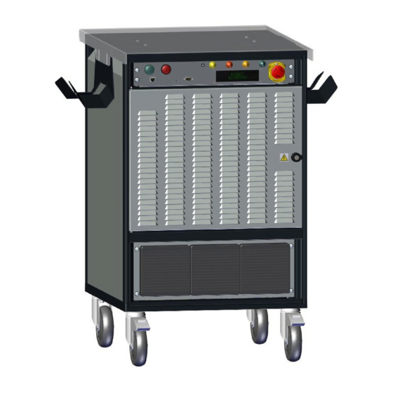
Page 8: Overview
Thanks to its « Harting » connector, its protocol cable can be changed in a few minutes, in Combo, CHAdeMO or GB. Based on many years of experience, IES mobile chargers provide a robust solution to facilitate the development of new vehicles by manufacturers. -
Page 9: Control Panel
User manual DUM1017795-EN Control panel ❶ ❷ ❸ ❹ ❺ ❻ ❼ ❽ DC CHARGER 50KW IES-SYNERGY ⓬ ⓫ ❿ ❾ Position Description “START” button to launch a charge “STOP” button to stop the charge Voltage presence indicator light “Charger ready”... -
Page 10: Connection Panel
Note: May change depending on version or technical modification Battery harness harting connector ⓰ ⓱ ⓲ ⓳ Position Description GND module + BAT module - BAT module Signal 20 pins module Note: May change depending on version or technical modification www.ies-synergy.com... - Page 11 Connector connection check Ground “Control Pilot” Ground S&S1 Start & Stop charge 1 S&S2 Start & Stop charge 2 +12V +12V P&P Charge permission & prohibition Ground CAN L CAN_H CAN H CAN_L Internal use Internal use Not used Not used www.ies-synergy.com...
-
Page 12: Specification
< 3sec. for asymmetrical fault Response time (tan) < 62sec. for symmetrical fault Self test time At power on and every 60s during charge. Non-symmetrical fault detection done continuously Measurement method Symmetrical fault detection every minute Isolation controller integrity check before each charge www.ies-synergy.com... - Page 13 Max output current will be adapted versus maximum carrying current of the vehicle plug. Output current can be even reduced with the power derating versus temperature. Potential derating above 30°C. Refer to the current derating curve according to the mains voltage. www.ies-synergy.com...
-
Page 14: Handling And Storage Instructions
RISK OF INJURY DUE TO DROPPING OR FALLING • Follow specified procedures for hoisting operations. • Take measures to prevent falling when you carry or transfer the unit. Failure to follow these instructions can result in minor or moderate injury. www.ies-synergy.com... -
Page 15: Installation
• This equipment shall be installed, adjusted, and serviced by qualified electrical personnel familiar with the construction and operation of this type of equipment and associated hazards. Failure to follow these instructions can result in death or serious injury www.ies-synergy.com... -
Page 16: Input Harness Connection
2. Remove the circuit breaker hatch cover - position ❷ 3. Reset the charger internal input circuit breaker (upper position) - position ❸ 4. Close the circuit breaker hatch ❶ 5. Fix the circuit breaker hatch cover using the screws (x6) G Recommended torque: 2 N.m www.ies-synergy.com... -
Page 17: Battery Harness Installation
• Be sure to mechanically lock the connectors before connecting the charger to the mains. Failure to follow these instructions can result in death or serious injury Ouput cables and connectors are described below: IES ref. Description Length Manufacturer... -
Page 18: Connector And Cable Support Installation
1. Place the supports MKBRN018011 (x2) on the top of the charger positioning them securely at the end of the slotted holes - position ❶ 2. Fix the supports using the screws FXVIS012307 (x4) - position ❷ G Recommended torque: 4 N.m ❷ ❷ ❶ ❶ www.ies-synergy.com... -
Page 19: Installation Of The Plexiglass Cover
1. Place without tightening completely the screws FXVIS012307 (x4) of the cover MKBRN018953 on the con- nector and cable supports - position ❶ 2. Place the cover - position ❷ 3. Fix the cover tightening the screws. G Recommended torque: 3 N.m ❷ ❶ ❶ www.ies-synergy.com... -
Page 20: Charger Operation
Failure to follow these instructions can result in death or serious injury Turn the disconnecting device to the position “I ON” to power up the charger. The charger displays its name after a startup phase represented by “...” : XS50 Keywatt by IES Universal Charger Choose the charging mode... -
Page 21: Chademo Mode
Connect the charging cable to the vehicle (secure firmly). Press the “START” button ❶ → The LED “CHARGER READY” ❹ flashes. The charger starts to communicate with the vehicle. STARTING SEQUENCE STARTING COMMUNICATION Communication has been established. LOCKING CONNECTOR www.ies-synergy.com... - Page 22 If there is no failure, the charge starts. CHARGING 30min 23A 360V 40% The display indicates the time left, the charging current and voltage and the current battery capacity. → The LED “CHARGE” ❼ flashes with a long pulse for 2 seconds. www.ies-synergy.com...
- Page 23 The charger performs the stop charge procedure. Charging is stopped either by the BMS or by the operator pressing the “STOP” button ❷. → The charge status indicator flashes slowly for 2 seconds. Note: The language can be configured via CCU Manager. www.ies-synergy.com...
-
Page 24: Combo Mode
The LED “CHARGER READY” ❹ flashes. Connect vehicle to start charge 9 In the event of an error, the charger will display one of the two messages below: Pwr module failure No power module 0 OK and 2 Fail www.ies-synergy.com... - Page 25 If there is no failure, the charger launches a precharge phase (this step depends on the EV). PRECHARGING... 1000 mA 320V Once the precharge level is reached and after receiving the charge permis- CHARGING… sion, the charger displays → www.ies-synergy.com...
- Page 26 Please disconnect EV The charger performs the stop charge procedure. Charging is stopped either by the vehicle or by the operator pressing the “STOP” button ❷. → The LED “CHARGE” ❼ flashes with a long pulse for 2 seconds. www.ies-synergy.com...
-
Page 27: Mode
Connect the charging cable to the vehicle (secure firmly). → The LED “CHARGER READY” ❹ flashes. Vehicle connected and press the GREEN button Then the charger performs the insulation test. INSULATION TEST... INSUL. TEST COMPLETED successfully 9 If there is an insulation failure: Cancel charge... INSULATION FAILURE!! www.ies-synergy.com... - Page 28 Please disconnect EV The charger performs the stop charge procedure. Charging is stopped either by the vehicle or by the operator pressing the “STOP” button ❷. → The LED “CHARGE” ❼ flashes with a long pulse for 2 seconds. www.ies-synergy.com...
- Page 29 User manual DUM1017795-EN Emergency Stop messages → The LED “FAILURE” ❺ flashes. Emergency Stop... Manual Emergency Stop → Emergency Stop!! Software Emergency Stop → Emergency Stop!! PSU connection lost Internal Fault Emergency Stop → www.ies-synergy.com...
-
Page 30: List Of Error Messages
Earth fault current detected by charger "ChargerMalfunction" During battery charging - Charger power supervisor (not CCU) stops charge, af- ter detecting output overvoltage. - Charge aborted by pressing “STOP” button. "PSU ERROR ARU" Software emergency stop requested by the power su- pervisor (internal). www.ies-synergy.com... - Page 31 "Error Timeout : EV Ready to Charge State not The charger has not received the ready to charge flag received" (Timeout is 40s) "Error No message or Client Disconnected" The charger has detected that the EV is present, but the EV has not sent a request. www.ies-synergy.com...
-
Page 32: Maintenance
Failure to follow these instructions can result in death or serious injury Fuse ref. Location 200A fuses (x2) installed on the output bat- FUCRT011930 tery side 10A fuses (x3) (FU1, FU2, FU3) installed on the FUCRT015901 mains board (CRAUX017939) www.ies-synergy.com... - Page 33 • Conduct a visual inspection of the charging cable and ensure that cable does not show any visual damage or deformation. • Conduct a visual inspection of the charging connector and ensure that it does not show any visual damage, arcing or rust. www.ies-synergy.com...
-
Page 34: Protecting The Environment
Products have been designed so that their components can be processed by conventional procedures: decon- tamination where this is recommended, reuse and/or dismantling in order to improve recycling performance, and crushing to separate out the rest of the materials. www.ies-synergy.com... - Page 35 User manual DUM1017795-EN Notes www.ies-synergy.com...
- Page 36 Tel: +33 (0)4 99 13 62 80 Tel: +49(0)80244633980 Fax: +33 (0)4 99 13 62 81 IES-Synergy Inc. (USA) IES WANMA New Energy (China) 330 East Maple Rd Building No 4, Wellong Technology Park Unit U No. 88 Jiang Lin Rd...
Need help?
Do you have a question about the Keywatt 50 Cube and is the answer not in the manual?
Questions and answers
Hello, i would like to know info about price for Keywatt 50. And second question, is it DC and AC charger? Thank You for Your answer.