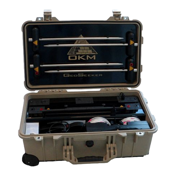
OKM FS Future Series User Manual
Hide thumbs Also See for FS Future Series:
Table of Contents

Advertisement

Quick Links

FS Future Series
®
GeoSeeker
User's Manual

Advertisement

Table of Contents
loading

Summary of Contents for OKM FS Future Series

  • Page 1 FS Future Series ® GeoSeeker User's Manual...
  • Page 2 Any information contained in these operating instructions may be changed without prior notice. OKM does not make any warranty for this document. This also applies without limitation to implied assurances of merchantability and fitness for a specific purpose. OKM does not assume any responsibility for errors in this manual or for any incidental or consequential damage or loss associated with the delivery, exploitation or usage of this material.
  • Page 3: Table Of Contents

    6 Preparing and maintaining the equipment ................... 6.1 Preparing the Controller ......................6.1.1 Placing and charging the batteries ..................6.1.2 Mounting the Tablet PC holder .................... 6.1.3 Mounting the Voltage Cable Drums ..................6.2 Preparing the Power Box ......................OKM GmbH www.okmmetaldetectors.com...
  • Page 4 8.3.2.4 Impervious layers ......................67 9 Tips and Tricks ............................. 9.1 Improving your scan results ......................9.2 Speeding up your measurement ....................9.2.1 Operation with 3 people ....................... 9.2.2 Operation with 5 people ....................... 9.3 Measurements under tough soil conditions .................. OKM GmbH www.okmmetaldetectors.com...
  • Page 5 Figure 8.1: Measure values as indicated during a measurement ............62 Figure 8.2: Graphical 3d representation of an active scan ..............63 Figure 8.3: Graphical 3d representation of a passive scan ..............64 Figure 8.4: Example of a passive measurement – flowing water ............. 65 OKM GmbH www.okmmetaldetectors.com...
  • Page 6 Figure 9.2: Electrodes have to be equally set into the ground ..............70 Figure 9.3: Operating the GeoSeeker with 3 people ................71 Figure 9.4: Operating the GeoSeeker with 5 people ................71 Figure 9.5: Drilling a hole and refilling it for the electrode ..............72 OKM GmbH www.okmmetaldetectors.com...
  • Page 7: Introduction

    1 Introduction HAPTER Introduction...
  • Page 8: Preface

    1.1 Preface Dear Customer, first of all we would like to thank you in choosing a product manufactured by OKM. The present product is based on a geoelectrical measuring method utilizing the Schlumberger technique to measure the resistivity of different soil layers.
  • Page 9: Important Notes

    Avoid using this equipment around active military installations and airports or where there may be other devices that may hamper the signals received. Radars for aircraft, boats and weather reporting may lower the units capabilities. OKM GmbH www.okmmetaldetectors.com...
  • Page 10: Voltage / Power Supply

    Curved or round objects should be a sign of alarm, especially if buttons, rings or little pegs can be identified or felt. The same applies to recognizable ammunition or bullets and shells. Leave that stuff alone and where it is, do not touch anything and, most importantly, do not take any of those items home OKM GmbH www.okmmetaldetectors.com...
  • Page 11 Moving such an object may cause those crystals to produce friction, leading to an explosion. If you come across such relics, mark the place and do not fail to report the find to the police or proper authority. Such objects always pose a danger to the life of hikers, walkers, farmers, children and animals. OKM GmbH www.okmmetaldetectors.com...
  • Page 13: Technical Specifications

    2 Technical specifications HAPTER Technical specifications...
  • Page 14: Controller (Receiving Unit)

    Weight ............................. 0.52 kg Equates 8 AA batteries; Use only boost chargeable NiMh batteries or primary cells with a minimum capacity of 2000 mAh; Do not use other kind of batteries with the supplied charger (danger of explosion); OKM GmbH www.okmmetaldetectors.com...
  • Page 15: Cable Drums

    Weight ............................. 0.65 kg Cable Length ............................26 m Markers ..............................25 2.5 Tablet PC, Minimum requirements Operating System ....................Android 4.0.3 or higher Wi-Fi / WLAN ..........................Required USB Chargeable ........................Micro-USB-B Display ..................... 7” Tablet Screen, Outdoor Brightness OKM GmbH www.okmmetaldetectors.com...
  • Page 17: Scope Of Delivery

    3 Scope of delivery HAPTER Scope of delivery...
  • Page 18 Voltage Cable Drum (120 mm cable drum) AA batteries, rechargeable Tablet Holder Android Tablet PC User manual Extension cable, 2 m Charger for Controller Charger for Power Box Electrode USB Power Pack with charger and travel adapter Table 1: Scope of delivery OKM GmbH www.okmmetaldetectors.com...
  • Page 19: Control Elements

    4 Control elements HAPTER Control elements In this section you will learn more about the fundamental use of all control elements for this measuring instrument. All connections, inputs and outputs are explained in detail.
  • Page 20: Electrodes

    Voltage Electrodes (electrodes with black socket) with the Controller. 4.2.1 Power Cable Drums (Ø 290 mm) The two larger cable drums – also called “Power Cable Drums” – are the link between the Power Box and the Power Electrodes. OKM GmbH www.okmmetaldetectors.com...
  • Page 21: Voltage Cable Drums (Ø 120 Mm)

    15 and will help you to place the electrodes at the right position during the measurement. 4.2.2 Voltage Cable Drums (Ø 120 mm) The two smaller cable drums – also called “Voltage Cable Drums” – are the link between the Controller and the Voltage Electrodes. OKM GmbH www.okmmetaldetectors.com...
  • Page 22: Controller

    25 and will help you to place the electrodes at the right position during the measurement. 4.3 Controller The Controller is responsible to measure the voltage between the measure electrodes. Figure 4.4 shows all control elements of the Controller. OKM GmbH www.okmmetaldetectors.com...
  • Page 23: Figure 4.4: Control Elements Of The Controller

    Electrical Connector / Small Cable Drum: There are two small cable drums which can be mounted to the electrical connectors of the Controller. These Voltage Cable Drums are used to connect the Controller with the two Voltage Electrodes (electrodes with red socket). OKM GmbH www.okmmetaldetectors.com...
  • Page 24: Tablet Holder

    Top Bracket / Bottom Bracket: These two brackets keep the Tablet PC in place after tighten the Clip. 4.5 Power Box The Power Box is used to inject electrical power into the underground which could be measured by the Controller afterwards. Figure 4.6 shows all the control elements of the Power Box. OKM GmbH www.okmmetaldetectors.com...
  • Page 25: Figure 4.6: Control Elements Of The Power Box

    Charger LED: The Charger LED represents the current charge condition of your internal batteries. As long as the Charger LED is shining red the charging process is still in progress. As soon as the LED turns green your internal batteries are fully charged. OKM GmbH www.okmmetaldetectors.com...
  • Page 26 There are two Power Electrodes with a red socket as well as two Voltage Electrodes with a black socket. The Power Electrodes are used to inject power - generated by the Power Box - into the ground. The Voltage Electrodes are used to measure the voltage of the underground utilizing the Controller. OKM GmbH www.okmmetaldetectors.com...
  • Page 27: Android Application

    5 Android Application HAPTER Android Application In this section is explained how to prepare your Tablet PC with the Android application.
  • Page 28: Download & Installation

    After installation you have to activate both the Controller and the Power Box. Detailed information about the activation process you can read in chapter “Activation” on page Fehler: Referenz nicht gefunden. In case of any troubles please contact your local dealer for additional help! OKM GmbH www.okmmetaldetectors.com...
  • Page 29: Operating Modes And Functionality

    Table PC everything is already set up properly and ready to go. Support Information • On this screen you will find the contact details for OKM as well as the current firmware version of your equipment. 5.2.1 New Measurement This is the option of your choice if you are going to create a new measurement.
  • Page 30: Figure 5.3: New Measurement - Creation Process

    Figure 5.4: New Measurement - Project title / notes You cannot continue without entering any title. This project title should be unique so you can easily browse your measurement out of others. After typing your title tap on "Next" to select your preferred scan mode. OKM GmbH www.okmmetaldetectors.com...
  • Page 31: Figure 5.5: New Measurement - Scan Mode

    In case you have selected the passive scan mode this step will be skipped and you will continue with entering the field dimensions. Figure 5.6: New Measurement - Scan profile After selecting an active scan mode there are following scan profiles available: Complete Measurement • Single Measurement • OKM GmbH www.okmmetaldetectors.com...
  • Page 32: Figure 5.7: New Measurement - Depth Settings

    This information is also very important to physically mark your scan points outside. Detailed information concerning the preparation of your scan field you can read in chapter “7 Conducting a measurement“ on page 47. OKM GmbH www.okmmetaldetectors.com...
  • Page 33: Figure 5.9: New Measurement - Arrangement Of Electrodes

    Power Box and right Power Electrode in terms of distance markers (numbered from 1 to 15) B … is the distance between left Voltage Electrode and Controller as well as the distance • between Controller and right Voltage Electrode in terms of distance markers (numbered from 1 to 25) OKM GmbH www.okmmetaldetectors.com...
  • Page 34: Continue Measurement

    If you tap a long time on one of those entries a context menu is opening where you can select one of the following actions: Continue • Select this action to continue the unfinished measurement. View • Select this action to view the 3d representation of the unfinished measurement. Delete • Select this action to delete the selected measurement. OKM GmbH www.okmmetaldetectors.com...
  • Page 35: View Measurement

    Select this action to view the 3d representation of the unfinished measurement. Delete • Select this action to delete the selected measurement. Menu Perspective View Local Color Adjustment Front View Right View Top View Global Color Adjustment Figure 5.12: View Measurement - 3d representation OKM GmbH www.okmmetaldetectors.com...
  • Page 36: Activation

    Power Box. Without a proper activation you cannot create any new measurement. First you have to enter the serial number of your Power Box/Controller and after that you have to enter the corresponding activation code as printed on your activation card. OKM GmbH www.okmmetaldetectors.com...
  • Page 37: Support Information

    Android Application 5.2.5 Support Information Select this option to get more information about OKM's contact details as well as the firmware version of your equipment. Figure 5.14: Support Information This version number can be useful for our support team in case you need any technical support.
  • Page 39: Preparing And Maintaining The Equipment

    6 Preparing and maintaining the equipment HAPTER Preparing and maintaining the equipment In this section you will learn more about the preparation and maintenance of your equipment before starting a new measurement.
  • Page 40: Preparing The Controller

    NiMh batteries or primary cells with a minimum capacity of 2000 mAh or higher. Danger of Explosion !!! Never recharge alkali, zinc carbon or lithium batteries / primary cells. OKM GmbH www.okmmetaldetectors.com...
  • Page 41: Mounting The Tablet Pc Holder

    If you like to mount the Tablet PC holder to the Controller just put it into place and fix the Tablet PC as shown in figure 6.3 and described in section “4.4 Tablet Holder” on page 24. OKM GmbH www.okmmetaldetectors.com...
  • Page 42: Mounting The Voltage Cable Drums

    Please ensure that the metal connectors are all clean to have good electrical contact with the drum's inner connectors. While replacing the electrodes during a measurement you may detach the cable drums but as soon as you are ready to measure some new scan values you have to connect it back to the OKM GmbH www.okmmetaldetectors.com...
  • Page 43: Preparing The Power Box

    Charger LED shines green: Charging finished • As soon as the Charger LED shines green the charging process has finished and you can disconnect the charger. Do not power on your Power Box while charging. This would interrupt your charging process. OKM GmbH www.okmmetaldetectors.com...
  • Page 44: Creating A Wi-Fi Connection

    If successful you will see a network called “OKM_GeoSeeker” in your list of available networks. Figure 6.6: Enabling Wi-Fi Select “OKM_GeoSeeker” and enter the network password “GeoSeeker” (use correct upper and lower case). Confirm by tapping “OK”. OKM GmbH www.okmmetaldetectors.com...
  • Page 45: Figure 6.7: Entering Wi-Fi Password

    This Wi-Fi connection is now stored on your Tablet PC and will reestablish automatically if it is in range unless you connect to another network manually or the Tablet PC is connecting to any other public network. OKM GmbH www.okmmetaldetectors.com...
  • Page 47: Conducting A Measurement

    7 Conducting a measurement HAPTER Conducting a measurement In this section you will learn how to conduct a measurement with GeoSeeker.
  • Page 48: Basic Information

    Your chosen scan field resolution (distance between scan points) must match the object's • dimensions. This means you can only detect underground anomalies if you scan right on top of the hidden targets as well as the surrounding ground. OKM GmbH www.okmmetaldetectors.com...
  • Page 49: General Measurement Procedure

    Electrodes (electrodes with red socket) and the resulting voltage is measured with the two Voltage Electrodes (electrodes with black socket). By increasing (or decreasing) the distance of the Power Electrodes step by step the measure depth also increases (or decreases) accordingly, as shown in figure 7.3. OKM GmbH www.okmmetaldetectors.com...
  • Page 50: Figure 7.3: Power Injection Depth Depends On Electrodes Distance

    Figure 7.4: Available Scan Modes An active measurement is always injecting electrical power into the underground before measuring the voltage between the Voltage Electrodes whereas a passive measurement is only detecting natural voltage without any power injection. OKM GmbH www.okmmetaldetectors.com...
  • Page 51 This option is used to measure a single scan point only. This is mostly used to do some quick test measurements on your scan field to find potential places where you could do a more complex measurement. OKM GmbH www.okmmetaldetectors.com...
  • Page 52: Figure 7.5: Instruction Screen For Setting Up A Measurement

    After setting up your measurement your Tablet PC shows the initial setup of your electrodes. An example is shown in figure 7.5. Figure 7.5: Instruction screen for setting up a measurement You will now arrange all your equipment according to these instructions. For our example it will be as follows: OKM GmbH www.okmmetaldetectors.com...
  • Page 53 You have to move the Voltage Electrodes (black socket) • inwards to another cable marker (several cable markers might be skipped). This will be necessary if the measured voltage is too high. OKM GmbH www.okmmetaldetectors.com...
  • Page 54: Setting Up A Measurement

    Then you should place markers at each scan point according to your settings to assure a fluid measuring process. The picture from figure 7.2 on page 49 shows an example of how to mark your scan points. OKM GmbH www.okmmetaldetectors.com...
  • Page 55: Setting Up The Power Injection For Active Scan Modes

    Power Box. Unroll the cable of the Power Cable Drum by moving away from the Power Box until you reach the cable marker indicated by the Android application of your Tablet PC. OKM GmbH www.okmmetaldetectors.com...
  • Page 56: Setting Up The Voltage Measurement

    The voltage measurement equipment consists of the Controller with Voltage Cable Drums as well as the Voltage Electrodes. All those parts are equipped with black plugs or black sockets. This Voltage Line is used to measure the natural voltage (passive scan) or the generated potential difference (active scan) of the Power Line. OKM GmbH www.okmmetaldetectors.com...
  • Page 57 Put the Voltage Electrode next to the cable marker into the ground as deep as possible. Use a hammer if necessary. OKM GmbH www.okmmetaldetectors.com...
  • Page 58 Conducting a measurement Connect the cable of the Voltage Cable Drum with the Voltage Electrode. Repeat steps 2 to 5 for the second Voltage Cable Drum and Electrode. OKM GmbH www.okmmetaldetectors.com...
  • Page 59: Final Connection Schemas

    During a Quick Active Scan only the Voltage Electrodes have to be arranged around the current scan point. The Power Electrodes have to be arranged around the center of the scan field. As shown figure 7.7 the Power Electrodes and the Voltage Electrodes are not in one line but two. OKM GmbH www.okmmetaldetectors.com...
  • Page 60: Passive Scan

    7.3.4.3 Passive Scan During a Passive Scan only the Voltage Electrodes are used and have to be arranged around the current scan point. The Power Electrodes are not used at all. Figure 7.8: Arrangement of electrodes during Passive Scan OKM GmbH www.okmmetaldetectors.com...
  • Page 61: Analyzing A Measurement

    8 Analyzing a Measurement HAPTER Analyzing a Measurement In this section you will learn how to analyze a measurement by using the Android application.
  • Page 62: Interpretation Of Scan Values

    • the Controller. Power: The power is measured in Ampere (A) and indicates how much electrical current has • been injected into the underground by the Power Box. This value is only available in active scan modes. OKM GmbH www.okmmetaldetectors.com...
  • Page 63: Interpretation Of Graphical Representations

    In most cases the indicated depth is often higher than the real depth might be but it will give you a rough estimation where the objects of your desire may be. Each cube in the 3d graphic is representing a measure value of your scan field. OKM GmbH www.okmmetaldetectors.com...
  • Page 64: Passive Scan

    A passive scan is only showing the distribution of the natural occurring voltage. It is not possible to get an estimation of the depth of underground anomalies. Each cube in the 3d graphic is representing a measure value of your scan field. OKM GmbH www.okmmetaldetectors.com...
  • Page 65: Examples

    8.3.2 Active Measurements 8.3.2.1 Water Deposits The typical color of water deposits is blue. The following 3d graphics are showing an indication of water under the ground. Figure 8.5: Example of an active measurement - water deposit OKM GmbH www.okmmetaldetectors.com...
  • Page 66: Water Deposits With Areas Of High Resistivity

    Figure 8.7: Example of an active measurement - cavity After adjusting the colors you will see there is some type of cave in the measurement. OKM GmbH www.okmmetaldetectors.com...
  • Page 67: Impervious Layers

    This layer mostly appears at the transition of loosely soil to massive stone. Figure 8.8: Example of an active measurement - impervious layer / barrier After adjusting the colors it is very obvious that there is a complete layer in the measurement with high resistivity. OKM GmbH www.okmmetaldetectors.com...
  • Page 69: Tips And Tricks

    9 Tips and Tricks HAPTER Tips and Tricks In this section you will get some additional tips you should consider during your measurements.
  • Page 70: Improving Your Scan Results

    The electrodes have to be replaced a lot while conducting a measurement. This is really tough when you are operating the device just by yourself. So it is strongly recommended to work in a group of 3 or better 5 people. OKM GmbH www.okmmetaldetectors.com...
  • Page 71: Operation With 3 People

    Voltage Electrodes (black socket) which are connected to the Controller. Figure 9.4: Operating the GeoSeeker with 5 people So finally there is one person per electrode and the operator of the Tablet PC is only giving instructions and takes care about the whole scanning process. OKM GmbH www.okmmetaldetectors.com...
  • Page 72: Measurements Under Tough Soil Conditions

    (small cup) over each electrode shaft to improve the electrical ground contact. You have to assure that you water all electrodes with the same amount of water. This procedure has to be repeated each time after replacing the electrodes. OKM GmbH www.okmmetaldetectors.com...

This manual is also suitable for:

Geoseeker

Table of Contents