Sign In
Upload
Download
Table of Contents
Contents
Add to my manuals
Delete from my manuals
Share
URL of this page:
HTML Link:
Bookmark this page
Add
Manual will be automatically added to "My Manuals"
Print this page
×
Bookmark added
×
Added to my manuals
Manuals
Brands
OKM Manuals
Security Sensors
Future Series
User manual
OKM Future Series User Manual
Hide thumbs
Also See for Future Series
:
User manual
(12 pages)
1
2
Table Of Contents
3
4
5
6
7
8
9
10
11
12
13
14
15
16
17
18
19
20
21
22
23
24
25
26
27
28
29
30
31
32
33
34
35
36
37
38
39
40
41
42
43
44
45
46
47
48
49
50
51
52
53
54
55
56
57
58
59
60
61
62
63
64
page
of
64
Go
/
64
Contents
Table of Contents
Bookmarks
Table of Contents
Table of Contents
1 Introduction
Preface
Important Notes
General Notes
Possible Health Hazards
Surrounding Area
Voltage
Data Safety
Maintenance and Services
Danger of Explosion During Excavation
2 Technical Specifications
Control Unit
Wireless Data Transfer
Super Sensor
Computer, Minimum Requirements
3 Scope of Delivery
4 Data Transfer Via Bluetooth
Installation of Bluetooth Software
Install Software and Driver
Figure 4.1: Start Screen When Inserting in the Software CD
Figure 4.2: Installation of Bluetooth Software, Step 1
Figure 4.3: Installation of Bluetooth Software, Step 2
Figure 4.4: Installation of Bluetooth Software, Step 3
Figure 4.5: Installation of Bluetooth Software, Step 4
Configurate Bluetooth Dongle
Figure 4.6: Installation of Bluetooth Software, Step 5
Figure 4.7: Installation of Bluetooth Software, Step 6
Figure 4.8: Installation of Bluetooth Software, Step 7
Figure 4.9: Installation of Bluetooth Software, Step 8
Figure 4.10: Installation of Bluetooth Software, Step 9
Figure 4.11: Installation of Bluetooth Software, Step 10
Setup Connection
Uninstall Bluetooth Software
Figure 4.12: Installation of Bluetooth Software, Step 11
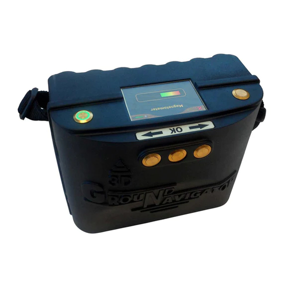
5 Control Elements
Breakdown of the Ground Navigator
Figure 5.1: 3D Ground Navigator with Control Unit and Super Sensor
Control Unit
Top/Front View
Figure 5.2: Control Elements of the Top and Front Panel
Bottom View
Figure 5.3: Control Elements on the Bottom Panel
Touchscreen
Figure 5.4: Touch Areas of the Display
Charging the Internal Battery
Super Sensor with LED Orbit
Figure 5.5: Super Sensor with LED Orbit
Bluetooth Headphones
Figure 5.6: Bluetooth Headphones with Accessories
6 Assembly
Charging the Control Unit
Preparing the Control Unit
Figure 6.1: Charging the Internal Battery of the Control Unit
Figure 6.2: Connecting the Super Sensor
Figure 6.3: Connecting the Power Pack (Optional)
Figure 6.4: Pocket the Optional Power Pack (Optional)
Figure 6.5: Power on Your Control Unit and Get Ready to Scan
7 Operating Modes
Figure 7.1: Splash Screen During Boot-Up
Ground Scan
Prepare a Ground Scan
Saving into Memory
Transferring to Computer
Conducting the Measurement
Figure 7.2: Display Representation in Operating Mode "Ground Scan
Figure 7.3: "Zig-Zag" Scanning (Left) and "Parallel" Scanning (Right)
Pin Pointer
Preparing a Pin Pointer Scan
Conducting a Pin Pointer Scan
Figure 7.4: Position of the Super Sensor During a Measurement
Figure 7.5: Pinpointing with Super Sensor
Analyzing a Pin Pointer Scan
Figure 7.6: Signature of a Ferromagnetic Metal Target
Figure 7.7: Signature of a Non-Ferromagnetic Metal Target
Figure 7.8: Signature of a Non-Metallic Target
Magnetometer
Preparing a Magnetometer Scan
Conducting a Magnetometer Scan
Figure 7.10: Pivoting or Turning the Probe Falisifies the Measurement
Figure 7.9: Probe Should Always Point Downwards and Should Not be Turned
Transfer to PC
Settings
Figure 7.11: Pairing Bluetooth Headphones
Figure 7.12: Information Screen
Headphones
Information
Bluetooth
Factory Reset
Figure 7.13: Changing Bluetooth Address
Figure 7.14: Reset to Factory Defaults
Back
Figure 7.15: Back Screen
8 Field Procedure
General Scanning Procedure
Scan Mode
Figure 8.1: Starting Position of a Scan Area
Regulation of the Number of Impulses Per Scanning Path
Figure 8.2: Scan Modes to Measure an Area
Figure 8.3: Effects of Changing the Number of Impulses and Their Distance
Figure 8.4: Comparison of Low and High Number of Impulses
Special Advices for Field Procedure
Figure 8.5: Different Walking Speeds During Scanning
Orientation of Probe
Parallel or Zig-Zag
Manual or Automatic Impulse Mode
Tips from the Trainers Themselves
Advertisement
Quick Links
Download this manual
FS Future Series
3D Ground Navigator
Version: 2
User's Manual
Table of
Contents
Previous
Page
Next
Page
1
2
3
4
5
Advertisement
Table of Contents
Need help?
Do you have a question about the Future Series and is the answer not in the manual?
Ask a question
Questions and answers
Related Manuals for OKM Future Series
Metal Detector OKM Future Series User Manual
Vlf emitter (12 pages)
Security Sensors OKM FS Future Series User Manual
(72 pages)
Security Sensors OKM eXp 4500 User Manual
Fs future series (94 pages)
Security Sensors OKM DELTA RANGER Quick Start Manual
(4 pages)
Security Sensors OKM Delta Ranger User Manual
Detector for treasure, gold and cavity hunt (62 pages)
Security Sensors OKM Delta Ranger DR-A01 User Manual
Detector for treasure, gold and cavity hunt (32 pages)
This manual is also suitable for:
3d ground navigator
Table of Contents
Print
Rename the bookmark
Delete bookmark?
Delete from my manuals?
Login
Sign In
OR
Sign in with Facebook
Sign in with Google
Upload manual
Upload from disk
Upload from URL


Need help?
Do you have a question about the Future Series and is the answer not in the manual?
Questions and answers