Table of Contents
Advertisement
Quick Links
Advertisement
Table of Contents

Related Manuals for OKM eXp 4500


Summary of Contents for OKM eXp 4500
- Page 1 FS Future Series eXp 4500 Version 1.5 User's Manual...
- Page 2 Any information contained in these operating instructions may be changed without prior notice. OKM does not make any warranty for this document. This also applies without limitation to implied assurances of merchantability and fitness for a specific purpose. OKM does not assume any responsability for errors in this manual or for any incidental or consequential damage or loss associated with the delivery, exploitation or usage of this material.
-
Page 3: Table Of Contents
..........................3.9 Antenna for Tunnel Detection ...................... 4 Scope of Delivery ..........................5 Assembly .............................. 6 Control Elements ..........................6.1 Breakdown of the eXp 4500 ......................6.2 Control Unit ..........................6.2.1 Front View ..........................6.2.2 Rear View ..........................OKM GmbH... - Page 4 8.3.2 Parallel or Zig-Zag? ......................8.3.3 Manual or automatic impulse mode? ..................8.3.4 Tips from the trainers themselves ..................9 Scanning Techniques ........................... 9.1 Super Sensor ..........................9.1.1 Super Sensor Training Marks ....................9.1.2 Super Sensor Orientation ..................... OKM GmbH www.okmmetaldetectors.com...
- Page 5 9.2 Control Scans ..........................OKM GmbH www.okmmetaldetectors.com...
- Page 6 Illustration 2.36: Uninstall USB drivers on Windows 7 - Step 1 ............34 Illustration 2.37: Uninstall USB drivers on Windows 7 - Step 2 ............34 Illustration 5.1: Rear View of eXp 4500 ..................... 42 Illustration 5.2: Connection of probe ....................42 OKM GmbH www.okmmetaldetectors.com...
- Page 7 Illustration 7.13: Signature of a non-ferromagnetic metal target ............. 57 Illustration 7.14: Signature of a non-metallic target ................57 Illustration 7.15: eXp 4500 Main Menu ....................58 Illustration 7.16: Tunnel Scan ......................59 Illustration 7.17: Automatic or Manual selection screen ..............59 Illustration 7.18: Tunnel shown in multi-line scan ................
- Page 8 Illustration 9.2: Add additional marks to the Super Sensor aids in the scan........91 Illustration 9.3: Super Sensor Orientation ..................92 Illustration 9.4: Control Scan the same line in both directions............93 Illustration 9.5: Traditional control scan procedure ................94 OKM GmbH www.okmmetaldetectors.com...
-
Page 9: Introduction
1 Introduction HAPTER Introduction... -
Page 10: Preface
Please take your time to read this User Manual and familiarize yourself with the operation, functionality and how to utilize the eXp 4500. We also offer training for your equipment in our factory and on-site. We strive to maintain worldwide dealer network for assistance and support. Please visit our web site for more information. -
Page 11: Important Notes
Please read the user manual of the software! 1.2.1 General Notes Being an electronic device, the eXp 4500 has to be treated with caution and treated with care as with any electronic device. Any failure to observe the safety precautions given or any use for purposes other than the ones it is designed for may result in damage or destruction of the processing unit and/or its accessories or connected components. -
Page 12: Data Safety
Prior to using your eXp 4500 please be sure that all batteries and accumulators are fully charged. Also allow the batteries to completely discharge before recharging them, regardless if you are working with the external battery or with internal accumulators. - Page 13 Moving such an object may cause those crystals to produce friction, leading to an explosion. If you come across such relics, mark the place and do not fail to report the find to the police. Such objects always pose a danger to the life of hikers, walkers, farmers, children and animals. OKM GmbH www.okmmetaldetectors.com...
-
Page 15: Install/Uninstall Usb Drivers On Windows
2 Install/Uninstall USB drivers on Windows HAPTER Install/Uninstall USB drivers on Windows In this chapter you will learn how to install the USB drivers, that are necessary to transfer data from the machine to your computer software. Please make sure to read the proper section appropriate to your Windows operating system. -
Page 16: Windows Xp
Illustration 2.2: Install USB drivers: Windows XP, Step 2 In other versions of Windows this window should not appear. In the following dialog window like figure 2.3 select the entry "Install software from a list …" and click Next. OKM GmbH www.okmmetaldetectors.com... - Page 17 Data carrier..Immediately another window appears where you click on the button Search ... Then select the file OKM_LE.INF , which you can find in the directory \drivers\usb_cable of your software CD. Afterwards you have to click on Open, OK and Next, to start the installation of the files. OKM GmbH www.okmmetaldetectors.com...
- Page 18 After successful installation of the driver a message like in figure 2.6 will appear on your computer screen. Now the drivers of your device are installed and you can transfer data to your PC. Illustration 2.6: Install USB drivers: Windows XP, Step 6 OKM GmbH www.okmmetaldetectors.com...
-
Page 19: Uninstall Usb Drivers On Windows Xp
After that a dialog like in figure 2.8 appears. There you can find the entry system and click twice on it. Illustration 2.8: Uninstall USB drivers: Windows XP, Step 2 The dialog from figure 2.9 appears on your screen. Click on the tab hardware and after that the button device manager. OKM GmbH www.okmmetaldetectors.com... - Page 20 USB devices will be shown. Illustration 2.10: Uninstall USB drivers: Windows XP, Step 4 Mark the device which you like to delete, which means "eXp 4500. Additionally the device may be listed as “OKM Quick Link”. Then click on the button.
- Page 21 Illustration 2.11: Uninstall USB drivers: Windows XP, Step 5 The dialog from figure 2.11 appears. Click there on the button OK. Now all drivers will be deleted from your computer. If needed you can now install the USB driver again correctly. OKM GmbH www.okmmetaldetectors.com...
-
Page 22: Windows Vista
Locate and install driver software (recommended). Illustration 2.12: Install USB drivers: Windows Vista, Step 1 At the next window, shown in figure 2.13, click on Don't search online. Illustration 2.13: Install USB drivers: Windows Vista, Step 2 OKM GmbH www.okmmetaldetectors.com... - Page 23 Illustration 2.15: Install USB drivers: Windows Vista, Step 4 Now you have completed the installation of the USB drivers in Windows Vista, which will be confirmed by presenting the message from figure 2.16. Illustration 2.16: Install USB drivers: Windows Vista, Step 5 OKM GmbH www.okmmetaldetectors.com...
-
Page 24: Update Usb Drivers On Windows Vista
Illustration 2.17: Update USB drivers on Windows Vista, Step 1 At the next screen, shown in figure 2.18, select View hardware and devices which can be found on the bottom of the left sidebar. Illustration 2.18: Update USB drivers on Windows Vista, Step 2 OKM GmbH www.okmmetaldetectors.com... - Page 25 Universal Serial Port Controllers . The text next to this device will depend on the device attached. In this example the device was an eXp 4500 device. Right click on the device (eXp 4500 in this example) to bring up a menu as shown below.
- Page 26 After entering the drivers location select Next to start the installation. Illustration 2.22: Update USB drivers on Windows Vista, Step 6 When the installation has finished the completion screen from figure 2.31 is displayed. Press Close to close this window and go back to the Device Manager. OKM GmbH www.okmmetaldetectors.com...
- Page 27 Install/Uninstall USB drivers on Windows The Device Manager will now show a device under Universal Serial Bus Controllers indicated in the screenshot below as OKM Quick Link . Illustration 2.23: Update USB drivers on Windows Vista, Step 7 The USB drivers are correctly updated/installed now and you can close the Device Manager window.
-
Page 28: Uninstall Usb Drivers On Windows Vista
Windows Vista provides an automatic method to delete driver files via check box "Delete the driver software for this device" on the uninstall dialog box. Just mark the check box and click OK to remove the installed USB drivers of your device. Illustration 2.25: Uninstall USB drivers on Windows Vista, Step 2 OKM GmbH www.okmmetaldetectors.com... -
Page 29: Windows 7
Illustration 2.27: Install USB drivers on Windows 7 - Step 2 Press the Windows 7 start button to bring up the start menu and select Control Panel as shown in figure 2.1. Illustration 2.28: Install USB drivers on Windows 7 - Step 3 OKM GmbH www.okmmetaldetectors.com... - Page 30 Illustration 2.29: Install USB drivers on Windows 7 - Step 4 At the next screen, shown in figure 2.20, select Device Manager which can be found under Devices and Printers . Illustration 2.30: Install USB drivers on Windows 7 - Step 5 OKM GmbH www.okmmetaldetectors.com...
- Page 31 The text next to this device will depend on the device attached. In this example the device was an eXp 4500 device. Right click on the other device (eXp 4500 in this example) to bring up a menu as shown below.
- Page 32 Illustration 2.34: Install USB drivers on Windows 7 - Step 9 When the installation has finished the completion screen from figure 2.28 is displayed. Press Close to close this window and go back to the Device Manager. OKM GmbH www.okmmetaldetectors.com...
- Page 33 Install/Uninstall USB drivers on Windows The Device Manager will now show a device under Universal Serial Bus Controllers indicated in the screenshot below as OKM Quick Link . Illustration 2.35: Install USB drivers on Windows 7 - Step 10 The USB drivers are correctly installed now and you can close the Device Manager window.
-
Page 34: Uninstall Usb Drivers On Windows 7
Windows 7 provides an automatic method to delete driver files via check box "Delete the driver software for this device" on the uninstall dialog box. Just mark the check box and click OK to remove the installed USB drivers of your device. Illustration 2.37: Uninstall USB drivers on Windows 7 - Step 2 OKM GmbH www.okmmetaldetectors.com... -
Page 35: Technical Specifications
3 Technical Specifications HAPTER Technical Specifications... -
Page 36: Exp 4500 Control Unit
Technical Specifications 3.1 eXp 4500 Control Unit Dimensions (H x W x D) ....................225 x 170 x 300 mm Weight ............................ about 1950 g Voltage ......................12 - 14.4 VDC, 22 W maximal Safety Class ............................IP40 Operating Time (full charged Power Pack, 25 °C) ..............about 3 hours Operating Temperature ...................... -
Page 37: Measurement Readings
3.8 GPR 100 cm Length ............................. 100 cm Weight ............................about 750 g Receiver ..................Dual Geophysical Phase Reader – EMSR Sensor technology ........................TCFX-01-A 3.9 Antenna for Tunnel Detection Length ............................... 50 cm Weight ............................about 520 g OKM GmbH www.okmmetaldetectors.com... - Page 38 Technical Specifications Receiver ..................Dual Geophysical Phase Reader – EMSR Sensor technology ........................TCFX-01-A OKM GmbH www.okmmetaldetectors.com...
-
Page 39: Scope Of Delivery
4 Scope of Delivery HAPTER Scope of Delivery... - Page 40 Professional Professional Plus eXp 4500 Control unit incl. carrying strap Wireless Headphones Telescopic rod assembly for GPR antenna Power Pack with charger and travel adapter...
-
Page 41: Assembly
5 Assembly HAPTER Assembly This section explains how to assemble the eXp 4500 and to prepare the unit for operation. - Page 42 Assembly Before using the eXp 4500 for a field measurement you should do some preparations. Please make notes to the following steps. Antenna Connector Power Pack Connector USB Connector Power On Joystick Connector Switch Illustration 5.1: Rear View of eXp 4500...
- Page 43 “Manual” mode, plug in the joystick to the control unit. In the event that the Joystick is not available, the Power On button can also be used. Simply press the Power on button to execute the measurement. Illustration 5.4: Connection of joystick OKM GmbH www.okmmetaldetectors.com...
-
Page 45: Control Elements
6 Control Elements HAPTER Control Elements In this section you will learn more about the fundamental use of all control elements for the eXp 4500 measuring instrument. All connections, inputs and outputs are explained in detail. -
Page 46: Breakdown Of The Exp 4500
Control Elements 6.1 Breakdown of the eXp 4500 The key components to the eXp 4500 are shown below. Headphones Carrying strap Control unit External power supply Telescopic rod assembly Supersensor T-mount GPR probe 25 cm Illustration 6.1: Control unit with standard GPR probe and Super Sensor Via the display you can see the navigation menu and all recorded scans. -
Page 47: Control Unit
Control Elements 6.2 Control Unit The control unit is the processing center of the eXp 4500. Via the control unit, various functions can be selected, all measured values can be recorded and stored. 6.2.1 Front View Figure 6.2 shows the front side of the control unit with its control elements. -
Page 48: Rear View
Black connector to Black plug. Via the connector for the USB cable the device can be connected to a computer via the USB cable. This is necessary to transfer data from the device to a computer. OKM GmbH www.okmmetaldetectors.com... -
Page 49: Operating Modes
7 Operating Modes HAPTER Operating Modes In this section you will learn more about the different operating modes of the eXp 4500. Every function is explained in its proper subsection. - Page 50 The eXp 4500 has the following primary operating modes: Ground Scan •...
-
Page 51: Ground Scan
Browse Ground Scans • See stored graphics. Delete All Ground Scans • Enables you to delete all saved ground scans. Back • Finish Ground Scan and go back to the main menu. Illustration 7.2: Ground Scan – Submenu OKM GmbH www.okmmetaldetectors.com... -
Page 52: New Ground Scan
– In the Automatic mode, the eXp 4500 will take the measurements automatically as predetermined in the “Field Length” selection. – In the Manual mode, the eXp 4500 will record a measurement point only when using the Joystick or by depressing the ON/OFF button. The eXp 4500 uses 6 impulses per meter. - Page 53 It is important that when doing a scan, that the objects in the ground do not move. Remember “Real Targets Don't Move!” Illustration 7.6: Graphical Representation of a Measurement in Operating Mode Ground Scan OKM GmbH www.okmmetaldetectors.com...
-
Page 54: Browse Ground Scans
The current selected measurement will be deleted, if you confirm the following message with “Yes”. Following you will go back to the main menu. Back • You go back to main menu. Illustration 7.8: Submenu: Browse Scans OKM GmbH www.okmmetaldetectors.com... -
Page 55: Delete All Ground Scans
7.10). This procedure is also available for the following operating modes with allocated memory: Illustration 7.9: Delete Scan files Ground Scan • Tunnel Scan • Mineral Scan • Thermo Scan • Illustration 7.10: Confirm Delete Scans OKM GmbH www.okmmetaldetectors.com... -
Page 56: Pin Pointer
There are 3 different signatures, from which you can recognize a specific characteristic of any target. Ferromagnetic metals Ferromagnetic targets have a positive- negative-signature. Illustration 7.12: Signature of a ferromagnetic metal target OKM GmbH www.okmmetaldetectors.com... - Page 57 The last of the typical signatures is represented in figure 7.14. It is the signature of all non-metallic targets and structures. These can be voids, tunnels or buried plastic pipes or boxes. You can recognize that there is only a negative amplitude (blue). OKM GmbH www.okmmetaldetectors.com...
-
Page 58: Magnetometer
Also, you may view the oscilloscope output on the monitor to be able to identify ferromagnetic materials in the ground. Illustration 7.15: eXp 4500 Main Menu The Magnetometer mode can be used with all the antennas except the FS-Thermoscan and the Antenna for Tunnel Detection. -
Page 59: Tunnel Scan
Rotate the multi-function control knob and select “Yes”. As soon as you depress the knob, it is important to begin walking immediately for the eXp 4500 is now recording data. Illustration 7.16: Tunnel Scan 7.4.2 Browse Tunnel Scans The option "Browse Tunnel Scans"... - Page 60 Since the Antenna for Tunnel Detection is shorter than the Super Sensor, it is important that the antenna be held in the vertical position. Do not OKM GmbH www.okmmetaldetectors.com...
- Page 61 The single line method is also a very accurate way of locating deeper voids and tunnels. When the single line method is used, the chances of making an error is greatly decreased. This method is used for an Illustration 7.20: Single line method used to locate tunnel initial investigation of an area. OKM GmbH www.okmmetaldetectors.com...
- Page 62 If the tunnel is very small then the maximum depth will be decreased and may be difficult to find. The depth of a tunnel cannot be accurately determined. The Visualizer 3D software is designed to measure depth starting from the surface disturbance to the object itself. OKM GmbH www.okmmetaldetectors.com...
-
Page 63: Mineral Scan
This is only for the purpose of prospecting and locating naturally occurring mineral fields and their deposits with the OKM eXp 4500. If you are looking for buried items of great value or other man made objects that have been placed into the ground, then this function is not correct for your application. -
Page 64: New Mineral Scan
Rotate the multi-function control knob and select “Yes”. As soon as you depress the knob, it is important to begin walking immediately for the eXp 4500 is now recording data. Illustration 7.21: Mineral Scan 7.5.2 Browse Mineral Scans The option "Browse Mineral Scans"... - Page 65 “No” to not save the scan. Though you will be able to see the scan on the eXp 4500 monitor, it is recommended to complete the analysis on the PC. The Visualizer 3D software will give you more tools to better identify mineral deposits.
-
Page 66: Scan Analysis
After transferring the scan images to your computer, you will now see a scan that is a straight line. This scan is now ready to begin the analysis. Illustration 7.24: Visualizer 3D Screen shot To see the differences within the scan rotate it to the side. Illustration 7.25: Side View of Scan Area OKM GmbH www.okmmetaldetectors.com... - Page 67 Illustration 7.27: Natural Mineral Field (additional example) Practical experience and the repeatability factor from several locations world-wide have made this color the one to watch for within the scans. As stated previously it is not an easy to recognize color. OKM GmbH www.okmmetaldetectors.com...
- Page 68 By using the “Parallel” the rotational factor is greatly minimized and almost removed. Another key factor when conducting any of the scans is to absolutely maintain the same height as much as possible (± 3 cm). OKM GmbH www.okmmetaldetectors.com...
-
Page 69: Additional Examples
Illustration 7.29: Shows a weak signal which can be smaller or deeper. These additional examples yielded gold that was embedded in the rock alongside with quartz and black sand. Illustration 7.30: Measure value indicating a non-ferrous anomaly OKM GmbH www.okmmetaldetectors.com... -
Page 70: Determining Position Of Anomaly
The beginning of a scan is normally always on the bottom right hand side of the software window. The positioning line was put into place using the arrow keys. Afterward the signal position can be found using simple distance measuring tools. OKM GmbH www.okmmetaldetectors.com... -
Page 71: Thermo Scan
Thermoscan enables users to conduct a thermal mapping of what is in the ground or what may be behind walls. The “Thermo Graph” and “Thermo Scan” functions of the eXp 4500 can help to locate Illustration 7.32: Thermo Scan Menu Illustration 7.33: Thermo Scan Icon... -
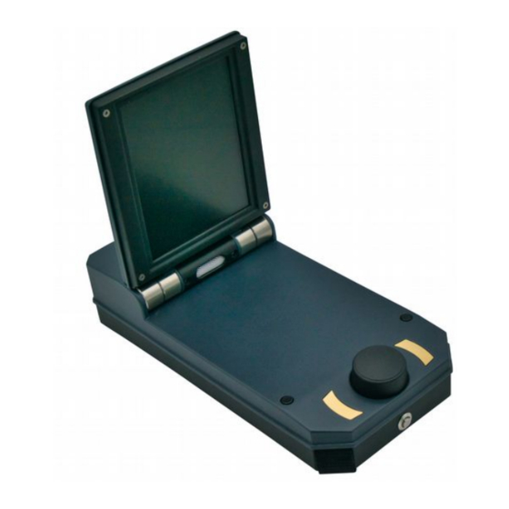
Page 72: Control Elements Of Fs-Thermoscan
Analog Display: On the analog display all measured values are visible. Laser Pointer: The laser pointer marks the position of the recording of the measured value, if activated. Connection Plug: With the connection plug you can connect the device to the eXp 4500. OKM GmbH... -
Page 73: Front View
By using the Calibration adjustment knob you can adjust the indicator of the analog display to the center. By using the Sensitivity adjustment knob you can adjust the range of values of the measurement. So the device can be aligned to the current temperature differences. OKM GmbH www.okmmetaldetectors.com... -
Page 74: Using The Fs-Thermoscan
The FS-Thermoscan has been pointed horizontally to the hillside and than moved slowly from the left to the right. In the area between 6 and 14 meters a clear decrease of temperature can be recognized – a possible indication for a subterranean void. OKM GmbH www.okmmetaldetectors.com... -
Page 75: Thermo Graph
Operating Modes 7.7 Thermo Graph The operating mode Thermograph offers a real time display of the measured results of FS-Thermoscan. To begin the function of the “Thermo Graph”, simply connect the FS-Thermoscan to the eXp 4500. Trend Chart Snap Shot Illustration 7.39: Thermograph Display... -
Page 76: Settings
Operating Modes 7.8 Settings Within the eXp 4500 there are several settings which can be configured. The following options are available. Language • Here you can set the desired language. The following languages are available: Illustration 7.40: German, English, ◦... -
Page 77: Exit
Whenever you wish to shut down your device. It is important to use the “Exit” function. Do not power off the eXp 4500 by turning off the power pack, select only the exit icon. Powering off the power pack may cause damage to the unit. -
Page 79: Field Procedure
8 Field procedure HAPTER Field procedure This chapter gives practical instructions about the general procedure of scanning an area. The different scanning methods and procedures will be explained in detail. -
Page 80: Major Rules To Follow
Field procedure 8.1 6 Major Rules to Follow Following the 6 PRIMARY RULES below will greatly increase your chances of success with the OKM line of equipment. Failure to follow the major rules will most likely result with errors. Do not turn or rotate the antenna or Super Sensor - this means that when the antenna is facing one direction, it must remain in that direction. -
Page 81: General Scanning Procedure
(measure points), which are recorded during one scanning path can be adjusted individually depending on the size of your scan area (length of scanning path). 8.2.1 Scan Mode There are two general techniques to surveying an area with the eXp 4500: Zig-Zag •... -
Page 82: Regulation Of The Number Of Impulses Per Scanning Path
This effective amount of measure points will be used for all further scanning paths of this measurement. Starting from the second scanning path, the device now stops automatically after the assumed number of impulses has been reached. OKM GmbH www.okmmetaldetectors.com... - Page 83 Figure 8.4: Comparison of low and high number of impulses Do not hesitate to record more measurements with different numbers of impulses. For example you can scan a large area before doing a second detailed precision measurement. Especially if searching for OKM GmbH www.okmmetaldetectors.com...
-
Page 84: Special Notes For Field Procedure
Inform yourself about the area, where you are searching. Does it make sense to detect here? Are • there historical references which confirms your speculation? What type of soil is on this area? Are there good conditions for data recording? Is it allowed to search at this place (eg. private property)? OKM GmbH www.okmmetaldetectors.com... -
Page 85: Orientation Of Probe
These stripes throughout a scan are commonly referred to as “Rotational Errors”. 8.3.2 Parallel or Zig-Zag? For skilled users of the eXp 4500 both scan modes are suitable. According to experience the best graphics has been received in the “Parallel” mode, because you are starting at the same point and traveling in the same direction. -
Page 86: Manual Or Automatic Impulse Mode
Get professional training. When you take advantage of receiving the training, either from the • factory or a qualified dealer, you will understand not only the use and operation of the OKM detector but also the software so much easier and be able to identify targets as well as errors. - Page 87 If you think that a red spot in the software is a real target, conduct a set of control scans and see if the target remains in the same place, or moves. If it moves, then it is not real. OKM GmbH www.okmmetaldetectors.com...
-
Page 89: Scanning Techniques
9 Scanning Techniques HAPTER Scanning Techniques Here you can find additional information on accessories that can compliment the basic unit. Keep in mind that the mentioned accessories are not included in the normal scope of delivery. -
Page 90: Super Sensor
• To use the Super Sensor with the eXp 4500, simply connect it to the main unit. Always hold the antenna vertical to the ground in your hand, whereby the cable should come out at the upper end of the antenna. -
Page 91: Super Sensor Training Marks
By putting several lines or marks on the Super Sensor (a colored electrical tape as example), others can easily see if the unit is being rotated. The user has the arrow on the top of the Super Sensor to aid in keeping the unit straight. OKM GmbH www.okmmetaldetectors.com... -
Page 92: Super Sensor Orientation
When the grip is too strong then the Super Sensor will not be vertical and it can be uneven like those on the right side of the image. The orientation of the antenna should not be changed during the complete measurement! OKM GmbH www.okmmetaldetectors.com... - Page 93 The other users need to ensure that the Super Sensor is not rotating or tilting and that it is remaining the same height over the ground. OKM GmbH www.okmmetaldetectors.com...
- Page 94 When looking for traditional buried objects this method is also used to ensure that the item is actual. The only difference is that with a traditionally buried object that the signal values will be greatly increased for the actual object(s). OKM GmbH www.okmmetaldetectors.com...
Need help?
Do you have a question about the eXp 4500 and is the answer not in the manual?
Questions and answers