
Related Manuals for Interlogix TruVision Multi-Imager


Summary of Contents for Interlogix TruVision Multi-Imager
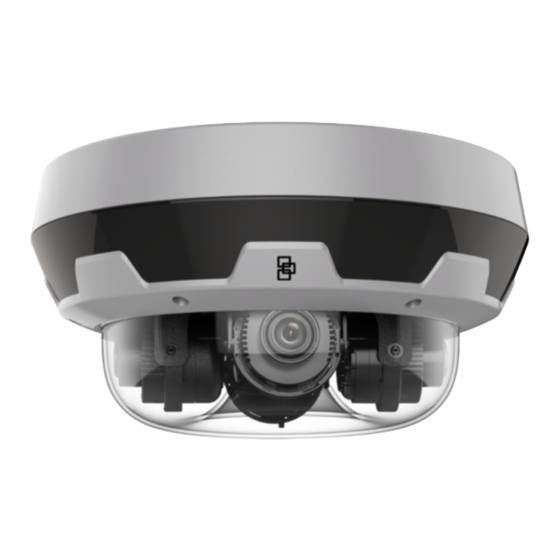
- Page 1 TruVision 20MP (4 x 5MP) 360 Degree Multi-Imager Camera Installation Guide P/N 1073687-EN • REV A • ISS 20FEB20...
- Page 2 Copyright © 2020 United Technologies Corporation, Interlogix is part of UTC Climate, Controls & Security, a unit of United Technologies Corporation. All rights reserved. Trademarks and patents Trade names used in this document may be trademarks or registered trademarks of the manufacturers or vendors of the respective products.
- Page 3 Safety Instruction: Improper use or replacement of the battery may result in explosion hazard. Replace with the same or equivalent type only. Dispose of used batteries in conformance with the local codes. Instructions de sécurité : L’utilisation ou le remplacement inadéquats de la pile peuvent entraîner un risque d’explosion.
- Page 4 Product warnings and THESE PRODUCTS ARE INTENDED FOR SALE TO AND INSTALLATION disclaimers BY QUALIFIED PROFESSIONALS. UTC FIRE & SECURITY CANNOT PROVIDE ANY ASSURANCE THAT ANY PERSON OR ENTITY BUYING ITS PRODUCTS, INCLUDING ANY “AUTHORIZED DEALER” OR “AUTHORIZED RESELLER”, IS PROPERLY TRAINED OR EXPERIENCED TO CORRECTLY INSTALL FIRE AND SECURITY RELATED PRODUCTS.
-
Page 5: Table Of Contents
IR illuminators 9 Accessing the micro SD/SDHC/SDXC slot 10 Mounting accessories 10 Install the camera to a mount 13 Using the camera with an Interlogix NVR or another system 15 Using the camera with TruVision Navigator 15 Specifications 15 Pin definitions 16... -
Page 6: Introduction
Introduction Product overview This is the installation manual for TruVision Multi-Imager 360 Degree IP Camera: Description TruVision Multi-Imager 360 Degree IP Camera, 20MP/4 x 5MP image TVS-5101 sensors, 2.8 to 12 mm motorized lenses, True D/N, WDR, 30 m IR, Audio,... -
Page 7: Contact Information And Manuals/Firmware
• Moisture: Do not expose the camera to rain or moisture, or try not to operate it in wet areas. Turn the power off immediately if the camera is wet and ask a qualified service person for servicing. Moisture can damage the camera and also create the danger of electric shock. -
Page 8: Package Contents
Package contents Check the package and contents for visible damage. If any components are damaged or missing, do not attempt to use the unit; contact the supplier immediately. If the unit is returned, it must be shipped back in its original packaging. -
Page 9: Cable Requirements
• Gray cloth • Installation manual • Equipment disposal sheet • Battery disposal sheet CAUTION: Use direct plug-in UL listed power supplies marked Class 2/CE certified or LPS (limited power source) of the required output rating as listed on the unit. Cable requirements For proper operation, adhere to the following cable and power requirements for the cameras. -
Page 10: Camera Description
Camera description Figure 1: Multi-imager camera 1. Cup base 11. IR transparent cover 2. Camera base 12. Camera positioning tray 3. Hi-PoE and network port 13. Lens 4. Power, 12 VDC 14. Reset button 5. Alarm input & output 1 15. -
Page 11: Install The Camera
Install the camera Note: Please refer to the camera configuration guide for detailed information on the camera configuration. To install the multi-imager camera to a ceiling: 1. Install the camera base to the ceiling. a) Use the camera base as a template to mark the mounting holes. b) If running the cables in to the side of the camera install the cable gland into the side of the camera base. - Page 12 Attach the safety cable d) Rotate the camera body to the end according to the direction arrow below. Make sure the ▲ mark of the camera body is aligned with the Lock mark of the camera base. 3. Insert the screws to secure the camera body to the base. 4.
-
Page 13: Ir Illuminators
Rotation axis. Range: 0° to 355° Tilting axis. Range: 0° to 135° Pan adjusting wheel. Range: -180° to +180° 5. Install the bubble assembly. Use the Torx wrench to fix the captive screws and secure the bubble assembly to the camera body. IR illuminators The camera’s built-in IR illumination provides high-quality video in low-light environments, even when there is no other illumination available. -
Page 14: Accessing The Micro Sd/Sdhc/Sdxc Slot
Note: The wall and pendant mounts are shipped with installation hardware. TruVision Multi-imager camera pendant mount (TVMI-PM) The multi-imager camera can be installed on a TVMI-PM pendent mount. The mount length is 116.5 × 57 mm (4.59 × 2.24 in.). - Page 15 The multi-imager camera can be installed on a TVMI-PM3 pendent mount. The mount length is 116.5 × 500 mm (4.59 × 19.68 in.). Pendent mount Example: Pendent mount with camera For further information, please refer to the “TruVision Multi-imager Camera Mount Installation Guide”. Installation Guide...
- Page 16 Extension pipe Example: Pendent mount and extension pipe with camera For further information, please refer to the “TruVision Multi-imager Camera Mount Installation Guide”. TruVision Multi-imager camera wall mount (TVMI-WM) The multi-imager camera can be installed on a TVMI-WM wall mount.
-
Page 17: Install The Camera To A Mount
Install the camera to a mount To install the multi-imager camera to a mount: 1. Install the camera base to the cup base using the screws provided. 2. Route the cables. 3. Attach the cup base to the mount and tighten the screw on the mount to secure the camera to the mount. - Page 18 b) Align the ▲ mark of the camera body with the Unlock mark the camera base to ensure that the catches in the camera base and body are correctly aligned. Then push the camera body upward. c) Rotate the camera body to the end according to the direction arrow below.
-
Page 19: Using The Camera With An Interlogix Nvr Or Another System
Using the camera with TruVision Navigator A camera must be connected to an Interlogix NVR in order to be operated by TruVision Navigator. Please refer to the TruVision Navigator user manual for instructions on operating the camera with TruVision Navigator. -
Page 20: Pin Definitions
205 mm 20 mm Without cup base: 120 mm 86 mm 46 mm 145.5 mm Pin definitions There are eight wires on a standard UTP/STP cable and each wire is color-coded. The following shows the pin allocation and color of straight and crossover cable connection: Figure 3: Straight-through cable White/Orange... - Page 21 Figure 4: Cross-over cable White/Orange White/Orange Orange Orange White-Green White-Green Blue Blue White/Blue White/Blue Green Green White/Brown White/Brown Brown Brown Please make sure your connected cables have the same pin assignment and color as above before deploying the cables in your network. Installation Guide...
Need help?
Do you have a question about the TruVision Multi-Imager and is the answer not in the manual?
Questions and answers