Table of Contents
Advertisement
Quick Links
Software: SPARKvue or
(2)
(1)
(7)
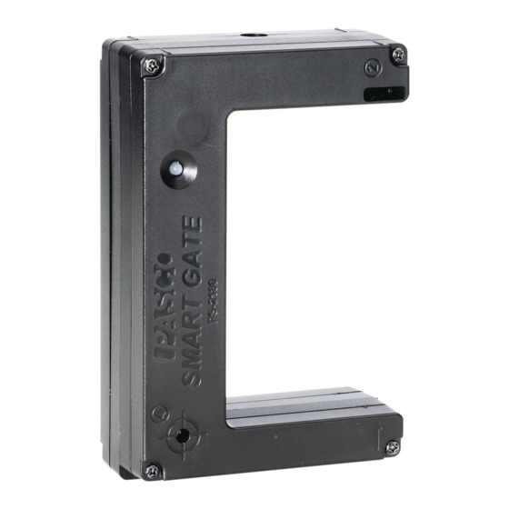
(1) Swivel Rod Clamp
(2) Bluetooth LED
(3) Device ID
(4) Battery LED
(5) Power Button
(6)Emitter Port 1
Required Item*
PASCO Data Collection Software
*See the PASCO catalog or the PASCO web site www.pasco.com for more information.
Wireless Smart Gate
PASCO Capstone
(3)
(4)
(5)
(16)
(6)
(6)
(8)
(7) Emitter Port 2
1
(8) Photogate Tape Slot
(9) 1/4-20 Threaded Hole
(10) Detector Port 1
(11) Detector Port 2
(12) (Port 3) Auxiliary Port
1
The Swivel Rod Clamp can be detached
PS-3225
Power: Rechargeable Battery
Connection: USB or
(12)
(11)
(10)
(8)
(9)
(17)
Legend
(13) Super Pulley Tab
(14) USB Port
(15) (Port 4)Laser Detector Port
(16) Indicator LED
(17) Micro USB Cable
Model Number*
see www.pasco.com
Reference Guide
013-16123A
(16)
(13)
(14)
(15)
(1)
Advertisement
Table of Contents

Related Manuals for PASCO Wireless Smart Gate


Summary of Contents for PASCO Wireless Smart Gate
- Page 1 (17) Micro USB Cable (6)Emitter Port 1 (12) (Port 3) Auxiliary Port The Swivel Rod Clamp can be detached Required Item* Model Number* PASCO Data Collection Software see www.pasco.com *See the PASCO catalog or the PASCO web site www.pasco.com for more information.
- Page 2 Bluetooth (BLE) or physically with a Micro USB cable. It measures the time for an object’s motion, such as a PASCO Cart, as the object blocks one or more beams of light. The Smart Gate has three detector ports and one Auxiliary port. There are slots for Ports 1 and 2 for Photogate Tape (ME-6663) or Photogate Tape, High Resolution (ME-6666).
-
Page 3: Hardware Setup
Power Button. The Bluetooth LED will blink to indicate that the sensor is ready to be “paired” with a device using the PASCO software.The sensor puts itself to sleep after one hour of inactivity if connected, and after several minutes if not connected. - Page 4 Note that half of the Wireless Smart Gate housing fits between the “rails” on each edge of one side of the Photogate Bracket, and the Wireless Smart Gate can be adjusted up or down. If you wish to adjust the Photogate Bracket to an angle relative to the...
- Page 5 Smart Gate measures the initial speed of the projectile and the Time-of-Flight Accessory measures total travel time. Using the Wireless Smart Gate with Photogate Tape High Resolution Photogate Tape (ME-6666) fits through the Photogate Tape Slot on the detector side of the Wireless Smart Gate. Smart Gate ME-6666 Photogate Tape,...
- Page 6 Cart (such as the ME-6950 PAScar). Use a Photogate Mounting Bracket (ME-9806) to mount the Wireless Smart Gate on the side of a PASCO Track (such as the ME-6960 PAStrack). Adjust the height of the Smart Gate to match the level of the desired flag pattern on the Picket Fence.
-
Page 7: Software Setup
Copy and paste the address into a web browser program to open the Sparkvue User’s Guide web page. Select SPARKvue “Help” Window • SPARKvue User’s Guide web page” • In PASCO Capstone, select PASCO Capstone Help from the Help menu, or press F1. 013-16123A... - Page 8 Indicator LED Information The Indicator LED on the top of the Wireless Smart Gate shines when the sensor is on and connected to the software and an object blocks the infrared beam entering Port 1 or Port 2. The Indicator LED also shines when a Photogate or a Time-of-Flight Apparatus is attached to the Auxiliary Port (Port 3) and the photogate beam is blocked or a projectile hits the Time-of-Flight pad.
- Page 9 • The “choose a path” window opens. Click or Touch 2. To “pair” the Wireless Smart Gate wirelessly to the computing device (e.g., computer or tablet), click or touch “Sensor Data” in the “choose a path” window. • The “Sensor Data Configuration” screen opens 3.
- Page 10 Wi rel ess Sma rt G a te A ss ign Smart Gate- S mar t G ate O nl y Assign SmartGate- Smart Gate Only The three choices are:. • “Smart Gate Only” • “Smart Gate and Auxiliary Port” Click or Touch the Menu arrow •...
- Page 11 PS-3225 Assign Sma rtGate- S mart Gate Only 2. Smart Gate Only - Photogate and Pendulum 1. Click or touch “Photogate and Pendulum” and then click or touch “OK” to accept the choice and close the dia- log. The “Edit Timer Properties:” panel is revealed. •...
- Page 12 Wi rel ess Sma rt G a te A ss ign Smart Gate- S mar t G ate O nl y 4. Smart Gate Only - Smart Pulley (Linear) 1. Click or touch “Smart Pulley (Linear)” to select it and then click or touch “OK” to accept the choice and close the dialog.
-
Page 13: Digital Input
“Time In Gate” and “Velocity In Gate” with “Time In Gate” as the default choice. This measurement gives the amount of time that the Wireless Smart Gate beam for Detector Port 1 was blocked. The “Velocity In Gate” measurement gives the speed and direction of the flag used to block the beam based on the Flag Length and the Time In Gate. - Page 14 The panel shows “Pulse Count” as the default choice. This measurement gives the number of times per “Count Time Interval” that the Wireless Smart Gate beam for Detector Port 1 was blocked. Assign SmartGate- Smart Gate and Auxiliary Port 1.
- Page 15 PS-3225 Assign S martGate- Smart Gate and A uxiliary Port 2. Click or touch the menu arrow for “Smart Gate and Auxiliary Port” to show the various choices. • Click or touch “Time of Flight” to select that choice. Click or Touch the Menu arrow 3.
- Page 16 Gate near one end of the track. Mount an Accessory Photogate near the other end of the track. Connect the Accessory Photogate to Auxiliary Port (Port 3) on the Wireless Smart Gate. Start recording data and then release the plunger so that the carts “explode” away from each other. The total momentum before the explosion is zero.
- Page 17 PASCO Accessory Photogate (ME-9204B). Connect the plug from the second photogate into Port 3, the Auxiliary Port on the back of the Wireless Smart Gate. In this mode, Detector Port 1 on the the Wireless Smart Gate will make measurements and so will the second photogate.
- Page 18 3. Also, the “Photogate Spacing” default value may need to be changed. Measure the distance separating the Wireless Smart Gate and the second photogate. Highlight the default value in the “Edit Timer Properties:” panel and enter the actual value. Click or touch “OK” to accept the change and close the dialog. The “Select Measurements for Templates”...
- Page 19 1. Auxiliary Port Only - Free Fall Adapter 1. Connect the plug from the PASCO Free Fall Adapter to Port 3, the Auxiliary Port on the Wireless Smart Gate. The Free Fall Adapter is designed to hold a metal ball at a height above the “receptor pad”. When the ball is released, timing begins, When the ball hits the pad, timing stops.
- Page 20 A “Connecting to the sensor” message appears briefly. • The Hardware Setup panel changes to show the image of the Wireless Smart Gate including Port 3, the Auxiliary Port. and Port 4, the Laser Detector Port. Port 3, the Auxiliary Port...
- Page 21 PS-3225 Connect the Sensor W ir ele ssly in PASCO C apstone Timer Setup Panel: What Everything Default choice: means in the Timer Setup Wizard. Click the name of the current timer to see other timers, if there are any.
- Page 22 Record and Display Data in PASCO Capstone First, Setup a Display for a “Smart Gate (Single Flag)” By default, PASCO Capstone shows a “workbook” page with eight pre-configured “QuickStart” page templates • The “Part A” illustration below shows the left half of the “workbook” page and the Tools palette.
- Page 23 • The experiment clock will show the elapsed time. The “Record” button changes to a “Stop” button. 2. Watch the digits displays as you pass a finger back and forth through the Wireless Smart Gate. • The “Speed Between Gates” will show a positive value. The “Velocity Between Gates” will show a positive value or a negative value depending on which direction your finger is moving when it goes through the sensor.
- Page 24 Next - Special Features of the Wireless Smart Gate • In the “Hardware Setup” panel, the Wireless Smart Gate picture shows the location of Port 3, The Auxiliary Port and Port 4, The Laser Detector Port. Port 3, Auxiliary Port Setup 1.
- Page 25 PS -3225 Por t 3 , Auxi liar y P or t Setup • 4. Click the small green star-shaped button to create Hardware a new timer that is labeled “New Timer” by default. Setup panel changes to show the Photogate Port 3 icon under...
- Page 26 Wireless Smart Gate P ort 3, Auxiliary Port Setup 7. Step 2 is now active. Also, the new photogate 9. Ignore the warning and click “Next” to open Step 4. (Photogate, Ch 1:3) has a checkmark. 10. Step 4 allows you to select the type of timer you would like to create.
- Page 27 Wireless Smart Gate. When Port 4 is selected, the Indicator LED shines red when the laser beam is blocked or is not shining into Port 4.
- Page 28 The Hardware Setup panel changes to show that Setup icon to open the Timer Setup panel the Wireless Smart Gate is connected.The panel shows the image of the Wireless Smart Gate including Port 3, the Auxiliary Port. and Port 4, the Laser Detector Port.
- Page 29 PS-3225 Port 4, Laser Detector Port S etup • The new Timer Setup panel is revealed and it 7. Click the “Select a Timer” menu button and then shows the choices in the Pre-Configured Timer select “Pendulum Timer”. menu. 6. Select “Create a pre-configured timer”. Make sure that there is a checkmark in front of “Laser Switch, Ch 1:4”...
-
Page 30: Probe Care And Maintenance
On the computing device, turn Bluetooth off and then back on. Retry. • If the Wireless Smart Gate will not turn on, use the micro USB cable to connect it to a USB port or charger. See the PASCO web site at www.pasco.com for more 9. -
Page 31: Specifications
Limited Warranty For a description of the product warranty, see the PASCO catalog. Copyright The PASCO scientific Instruction Manual is copyrighted with all rights reserved. Permission is granted to non-profit educational institutions for reproduction of any part of this manual, providing the reproductions are used only in their laboratories and classrooms, and are not sold for profit. -
Page 32: Appendix A: Bluetooth Compatibility
2012. The Mac Pro that debuted in December 2013 has Bluetooth SMART support. Exception: Before you upgrade to El Capitan (Mac OS X 10.11.x), if you have a Macintosh with LMP version “0x4” that requires the PS-3500 USB Bluetooth 4.0 Adapter, please contact PASCO Technical Support for further instructions. -
Page 33: Appendix B: Uk Timing Modes In Sparkvue
PS-3225 Appendix B: U K Timing Modes in SPARKvue Appendix B: UK Timing Modes in SPARKvue In addition to the previously described Smart Gate Timing Modes, SPARKvue also supports the UK Timing Modes. To access the UK Timing Modes, click or touch the menu icon in the upper left corner of the home screen. - Page 34 Wireless Smart Gate Appe ndix B : UK T iming Modes in S PARKvue By default, the Assign SmartGate window shows the four UK Timing Modes menu choices: • One Light Gate and Single Interrupt Card • Two Light Gates and Single...
- Page 35 The selected Display Template appears with “Speed at A” as the default measurement choice. 2. Click or Touch the green “Start” button to start collecting data. Watch the display as you pass a finger back and forth through the Wireless Smart Gate. •...
-
Page 36: Appendix C: Uk Timing Modes In Pasco Capstone
“OK” to close the window and return to the main briefly. workbook menu. • The Hardware Setup panel changes to show the image of the Wireless Smart Gate including Port 3, the Auxiliary Port. and Port 4, the Laser Detector Port. Port 3, the Auxiliary Port... - Page 37 PS-3225 Connect the Sensor W ir ele ssly in PASCO C apstone Smart Gate (Single Flag) Setup 2. Click the “Timer Setup” icon in the tools palette to open the Timer Setup panel. 1. Click the “Hardware Setup” icon in the Tools palette to close the “Hardware Setup”...
- Page 38 Wireless Smart Gate Connect t he Sens or W irelessly in P ASCO Capst one setting up a Timer in PASCO Capstone. You can 6. Click “Next” to open Step 4. go through the same process to create a Timer Setup for UK Timing Modes.
- Page 39 PS-3225 Connect the Sensor W ir ele ssly in PASCO C apstone 7. Click the Select a Timer menu button. 8. For this example, select “One Light Gate and Single Interrupt Card. • The default measurements are “Time” and “Speed/Velocity”. The “gate order” is at A. For this example, the “Accelertion”...
- Page 40 You can use Step 8 to enter a specific name for the timer. 13. Click “Finish”. • You can review the details of the Timer Setup and make changes if needed. 14. Setup to Record and Display data using PASCO Capstone as described previously. 013-16123A...
- Page 41 PS-3225 Connect the Sensor W ir ele ssly in PASCO C apstone Appendix D: Build a Custom Timer in PASCO UNDER CONSTRUCTION Capstone is See www.pasco.com for the latest version of this manual. 013-16123A...
- Page 42 Wireless Smart Gate Connect t he Sens or W irelessly in P ASCO Capst one 013-16123A...
Need help?
Do you have a question about the Wireless Smart Gate and is the answer not in the manual?
Questions and answers