Table of Contents
Advertisement
Quick Links
PASCO Wireless Smart Gate PS-3225
Software: SPARKvue or PASCO Capstone — Power: Rechargeable Battery
Bluetooth LED
Battery LED
Swivel
Rod
Device ID
Clamp
Depth =
4.0 cm
Port 1
Emitters
LED indicates
blocked port(s)
Port 3 for
Photogate
or similar
Tab for
device
Slot or
mounting
Super Pulley
Photogate
Tape
ME-9450A
Port 1
Receptors
Width = 7.2 cm
Allow 3 hours
for charging
012-16123A
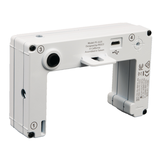
PASCO Wireless Smart Gate PS-3225
Software: SPARKvue or PASCO Capstone — Power: Rechargeable Battery
Bluetooth LED
Battery LED
Swivel
Rod
Device ID
Clamp
Depth =
4.0 cm
Port 1
Emitters
LED indicates
blocked port(s)
Port 3 for
Photogate
or similar
Tab for
device
Slot for
mounting
Super Pulley
Photogate
Tape
ME-9450A
Port 1
Receptors
Width = 7.2 cm
Allow 3 hours
for charging
012-16123A
LED indicates
blocked port(s)
Power
Button
Slot for
Photogate
Tape
Port 1
Receptors
USB Port
Port 4 for
laser beam
Port 1
Emitters
Micro USB Cable
LED indicates
blocked port(s)
Power
Button
Slot for
Photogate
Tape
Port 1
Receptors
USB Port
Port 4 for
laser beam
Port 1
Emitters
Micro USB Cable
www.pasco.com - (800) 772-8700
Initial Step: Connect and Charge It
Use the included micro USB cable to connect the sensor to a USB port or
a USB charger (such as PS-2575A). If connected to a USB port, the
Battery LED shines yellow to show the battery is charging. When battery
is charged, the Battery LED shines green. If connected to a USB charger,
the Battery LED shines yellow and the Bluetooth LED blinks red to
indicate that the sensor is ready to connect to a device (such as a
computer or tablet). Allow 3 hours for charging.
Collecting Data:
Follow the steps for your software program to connect the sensor
wirelessly to your computing device (e.g. computer or tablet).
SPARKvue
1. Press and hold the Power Button until the Bluetooth LED starts flashing
red. 2. Open SPARKvue and select Sensor Data. 3. Under Connected
Devices, select the sensor that matches your device ID. 4. Under
Templates, select Graph. 5. Select START to begin data collection.
PASCO Capstone
1. Press and hold the Power button until the Bluetooth LED starts flashing
red. 2. Open Capstone and In the Tools palette, click Hardware Setup to
open the panel. 3. Select the sensor that matches your device ID. 4. Click
Hardware Setup to close the panel. 5. In the Displays palette, select
Graph. 6. On the vertical axis of the graph, click Select Measurement,
then select a measurement (such as velocity). 7. Click Record to begin
data collection.
www.pasco.com - (800) 772-8700
nitial Step: Connect and Charge It
I
Use the included micro USB cable to connect the sensor to a USB port or
a USB charger (such as PS-2575A). If connected to a USB port, the
Battery LED shines yellow to show the battery is charging. When battery
is charged, the Battery LED shines green. If connected to a USB charger,
the Battery LED shines yellow and the Bluetooth LED blinks red to
indicate that the sensor is ready to connect to a device (such as a
computer or tablet). Allow 3 hours for charging.
Collecting Data:
Follow the steps for your software program to connect the sensor
wirelessly to your computing device (e.g. computer or tablet).
SPARKvue
1. Press and hold the Power Button until the Bluetooth LED starts flashing
red. 2. Open SPARKvue and select Sensor Data. 3. Under Connected
Devices, select the sensor that matches your device ID. 4. Under
Templates, select Graph. 5. Select START to begin data collection.
PASCO Capstone
1. Press and hold the Power button until the Bluetooth LED starts flashing
red. 2. Open Capstone and In the Tools palette, click Hardware Setup to
open the panel. 3. Select the sensor that matches your device ID. 4. Click
Hardware Setup to close the panel. 5. In the Displays palette, select
Graph. 6. On the vertical axis of the graph, click Select Measurement,
then select a measurement (such as, velocity). 7. Click Record to begin
data collection.
Connection:
or USB
support@pasco.com|
Connection:
or USB
support@pasco.com|
|
1
|
1
Advertisement
Table of Contents

Related Manuals for PASCO PS-3225


Summary of Contents for PASCO PS-3225
- Page 1 PASCO Wireless Smart Gate PS-3225 www.pasco.com - (800) 772-8700 Software: SPARKvue or PASCO Capstone — Power: Rechargeable Battery Connection: or USB Initial Step: Connect and Charge It Bluetooth LED Battery LED LED indicates blocked port(s) Use the included micro USB cable to connect the sensor to a USB port or a USB charger (such as PS-2575A).
- Page 2 Auxiliary port. The space between the emitters for Port 1 and Port 2 is 1.5 cm. There is a slot for Photogate Tape (ME-6663 or ME-6666) for Ports 1 and 2. Port 3 is the Auxiliary port for a PASCO Photogate or similar device. Port 4 is designed to work with a laser beam to allow measurement of an object too large to pass through the Wireless Smart Gate.
Need help?
Do you have a question about the PS-3225 and is the answer not in the manual?
Questions and answers