Table of Contents
Advertisement
Quick Links
1 ANI-1F1
Module for process control in CO
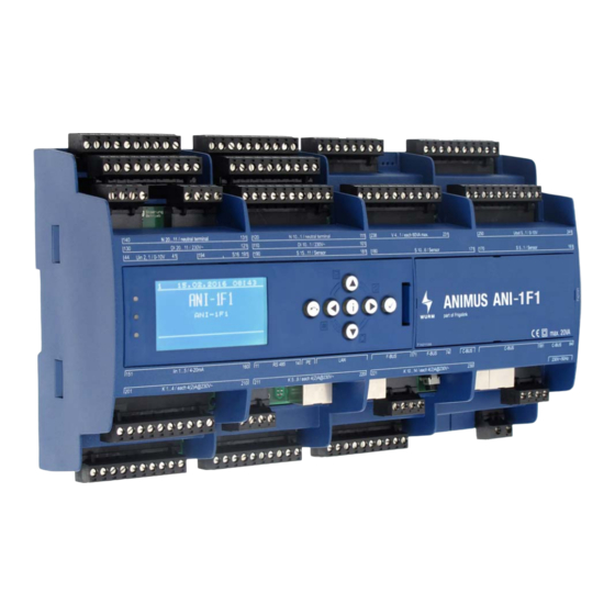
Fig. 1: ANI-1F1 - front view
1.1 Features
•
Standard compound controller with 3 compressors controlled by evaporation temperature
-
Compressor 1 constant (FC), compressors 2 and 3 directly controlled
-
Simple base load change
-
Monitoring of suction gas temperature
-
Oscillation protection function
-
Blocking time after compressor fault
-
Two-step load shedding and fast return flow
-
Operating hours counter for each compressor
•
Low temperature compressor control after pump-down
•
High and medium pressure control
•
Gas cooling fan control
•
Additional control circuits for:
-
Load shedding
-
Deheater
-
Fluid post-injection
-
Refrigerant monitoring
-
Heat recovery
-
Pressure monitoring
•
Integrated relay outputs
•
Bus connection by patch cable
•
Fastening via top-hat rail
•
Connection to the Wurm system through a Wurm CAN communication bus (C-BUS) and
FRIGODATA XP
Accessories
•
Control panel (ANI-C)
ANI-1F1_V2.1.4_PI_2018-06_EN.fm
refrigeration plants with compound and gas cooler control
2
Subject to technical changes
FRIGOLINK
ANI-1F1
1
Advertisement
Table of Contents

Related Manuals for WURM FRIGOLINK ANI-1F1


Summary of Contents for WURM FRIGOLINK ANI-1F1
-
Page 1: Ani-1F1
Integrated relay outputs • Bus connection by patch cable • Fastening via top-hat rail • Connection to the Wurm system through a Wurm CAN communication bus (C-BUS) and FRIGODATA XP Accessories • Control panel (ANI-C) ANI-1F1_V2.1.4_PI_2018-06_EN.fm Subject to technical changes... -
Page 2: Table Of Contents
FRIGOLINK ANI-1F1 Contents ANI-1F1 ....... . . 1 1.1 Features ..........1 1.2 Safety instructions . -
Page 3: Safety Instructions
Wurm GmbH & Co. KG Elektronische Systeme. Keep these instructions ready to hand for quick reference and pass them on with the device if the product is sold. -
Page 4: Circuit Diagram
Any software versions not listed are special solutions for individual projects and are not described in detail in this document. This document automatically ceases to be valid if a new technical description is issued. Manufacturer: Wurm GmbH & Co. KG Elektronische Systeme, Morsbachtalstraße 30, D-42857 Remscheid For further information, see our website at www.wurm.de... -
Page 5: Input Circuit Diagram
FRIGOLINK ANI-1F1 1.3.1 Input circuit diagram Fig. 3: ANI-1F1 - input circuit diagram Digital inputs DI 1 - DI 20 Terminal Digital input Potential Assignment DI 1 230V~ Access authorisation DI 2 230V~ Day/night signal DI 3 230V~ Load shedding (one constant run com- pressor) DI 4... -
Page 6: Analogue Inputs Uin 1, 2
FRIGOLINK ANI-1F1 Terminal Digital input Potential Assignment DI 11 230V~ Fault MT compressor DI 12 230V~ Fault MT compressor DI 13 230V~ Fault LT compressor DI 14 230V~ Fault LCL refrigerant underfill DI 15 230V~ Fault LCH refrigerant overfill DI 16 230V~ Fault PSL LP com- pound... -
Page 7: Analogue Inputs S 1 - S 16
FRIGOLINK ANI-1F1 Analogue inputs S 1 - S 16 Terminal Sensor input Sensor type Assignment 161/162 Suction gas tempera- ture MT compound (logging) 163/164 Pressure gas temper- ature MT compound 165/166 Pressure gas temper- ature LT compressor / desuperheating 167/168 External temperature 169/170 Temperature gas... -
Page 8: Output Circuit Diagram
FRIGOLINK ANI-1F1 1.3.2 Output circuit diagram Fig. 4: ANI-1F1 - output wiring diagram Digital outputs (relays) K 1 - K 14 Contact arrange- Terminal Digital output Assignment ment Changeover contact Alarm output Prio 1 K 1/ 4(2)A@230V~ Changeover contact Alarm output Prio 2 K 2 / 4(2)A@230V~ NO contact K 3 /... -
Page 9: Digital Outputs (Ssr) V 1 - V 4
FRIGOLINK ANI-1F1 Contact arrange- Terminal Digital output Assignment ment NO contact K 10 / Not available 4(2)A@230V~ NO contact K 11 / LT desuperheater fan 4(2)A@230V~ NO contact K 12 / Not available 4(2)A@230V~ NO contact K 13 / Not available 4(2)A@230V~ NO contact K 14 / Not available... -
Page 10: Communication Circuit Diagram
FRIGOLINK ANI-1F1 1.3.3 Communication circuit diagram Fig. 5: ANI-1F1 - communication circuit diagram Communication Terminal Potential Assignment C-BUS F-BUS RS 485 ANI-1F1_V2.1.4_PI_2018-06_EN.fm Subject to technical changes... -
Page 11: Installing
FRIGOLINK ANI-1F1 1.4 Installing The module is designed for top-hat rail installation. The housing is also suitable for installation in fuse boxes or distribution switch cabinets. Modules can be positioned side by side without gaps. WARNING! DANGER OF DEATH FROM ELECTRIC SHOCK! •... -
Page 12: Dismantling
FRIGOLINK ANI-1F1 Dismantling 1. Insert a flat-tip screwdriver in the openings in the fastening catches. 2. Pull the two fastening catches away from the housing until they are heard to click. 3. Swivel the bottom of the module gently away from the top-hat rail and towards yourself. 4.
Need help?
Do you have a question about the FRIGOLINK ANI-1F1 and is the answer not in the manual?
Questions and answers