Table of Contents
Advertisement
Quick Links
Module for process control in CO
1 ANI-2F1-A
Module for process control in CO
1.1
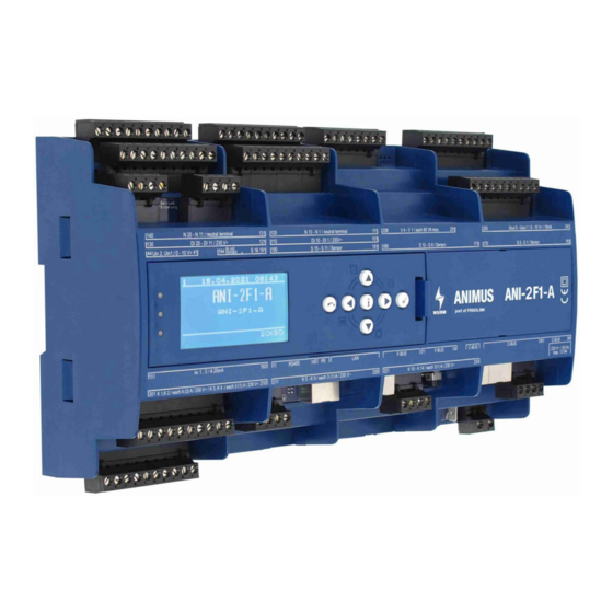
Front view
Fig. 1: Front view with ANI-C control panel
1.2
Features
•
Standard rack controller with up to 2 compressors controlled by evaporation temperature
-
Compressor 1 constant (FC), compressor 2 directly controlled
-
Frigotakt+
-
Monitoring of suction gas temperature
-
Oscillation protection function
-
Blocking time after compressor fault
-
3-step load shedding including Fastreturn
-
Operating hours counter and cycle counter for each compressor
•
High pressure and medium pressure control
•
Gas cooler fan control
•
Gas cooler monitoring
•
Refrigerant monitoring
•
CAN bus connection via patch cable and screw terminals
•
Fastening by top-hat rail
•
Can be locked to prevent unwanted parameter adjustment (SAC - Security Access Control)
•
Connection to the Wurm system via Wurm CAN communication bus (C-BUS) and
FRIGODATA XP
Accessories
•
Control panel (ANI-C)
ANI-2F1-A_V2.0.0_PI_2022-01_EN
2
refrigeration plants with rack and gas cooler control
2
Subject to technical changes
refrigeration plants with rack and gas cooler control
ANI-2F1-A
1
Advertisement
Table of Contents

Related Manuals for WURM ANI-2F1-A


Summary of Contents for WURM ANI-2F1-A
-
Page 1: Ani-2F1-A
• Fastening by top-hat rail • Can be locked to prevent unwanted parameter adjustment (SAC - Security Access Control) • Connection to the Wurm system via Wurm CAN communication bus (C-BUS) and FRIGODATA XP Accessories • Control panel (ANI-C) ANI-2F1-A_V2.0.0_PI_2022-01_EN... -
Page 2: Table Of Contents
ANI-2F1-A ........ -
Page 3: Safety Instructions
Wurm GmbH & Co. KG Elektronische Sys- teme. Keep these instructions ready to hand for quick reference, and pass them on with the device if the product is sold. - Page 4 Any versions not listed are special solutions for individual projects and are not described in detail in this document. This document will automatically cease to be valid if a new technical description is issued. Manufacturer: Wurm GmbH & Co. KG Elektronische Systeme, Morsbachtalstraße 30, D-42857 Remscheid You can find more information on our website at www.wurm.de.
-
Page 5: Circuit Diagram
ANI-2F1-A Module for process control in CO refrigeration plants with rack and gas cooler control Circuit diagram Fig. 2: Circuit diagram Power supply Terminal Power supply Potential Neutral 230V~ Functional earth (FE) Terminal Assignment Shield • To ensure failure-free operation and reliable data communication, connect the functional earth. -
Page 6: Input Circuit Diagram
ANI-2F1-A Module for process control in CO refrigeration plants with rack and gas cooler control 1.4.1 Input circuit diagram Fig. 3: Input circuit diagram Digital inputs DI 1 - DI 20 Terminal Digital input Potential Assignment DI 1 230V~ Not available... -
Page 7: Analogue Inputs: Voltage Uin 1 - Uin 2
ANI-2F1-A Module for process control in CO refrigeration plants with rack and gas cooler control Terminal Digital input Potential Assignment DI 17 230V~ HP rack fault DI 18 230V~ GC fan fault DI 19 230V~ UPS / gas warning 1... -
Page 8: Output Circuit Diagram
ANI-2F1-A Module for process control in CO refrigeration plants with rack and gas cooler control 1.4.2 Output circuit diagram Fig. 4: Output circuit diagram Digital outputs: Relays K 1 - K 14 Contact arrange- Terminal Digital output Assignment ment Change-over con-... -
Page 9: Digital Outputs Ssr V 1 - V 4
ANI-2F1-A Module for process control in CO refrigeration plants with rack and gas cooler control Digital outputs SSR V 1 - V 4 Contact arrange- Terminal Digital output (SSR) Assignment ment 231/232 V 1 Not used 233/234 V 2 Not used... -
Page 10: Communication Circuit Diagram
ANI-2F1-A Module for process control in CO refrigeration plants with rack and gas cooler control 1.4.3 Communication circuit diagram Fig. 5: Communication circuit diagram Communication Terminal Potential Assignment C-BUS F-BUS RS 485 ANI-2F1-A_V2.0.0_PI_2022-01_EN Subject to technical changes... -
Page 11: Installing
ANI-2F1-A Module for process control in CO refrigeration plants with rack and gas cooler control Installing The module is designed for top-hat rail installation. The housing is also suitable for installation in fuse boxes or distribution switch cabinets. Modules can be positioned side by side without gaps. -
Page 12: Dismantling
For details of output assignments, see: Chapter 1.4.2 “Output circuit diagram” on page 8. For details of sensor assignments, see: Chapter “Analogue inputs: Sensors S 1 - S 16“ on page 7. • For information about the ANI-2F1-A functions, please see the product manual for the ANI-2F1. HINWEIS ANI-2F1-A_V2.0.0_PI_2022-01_EN...
Need help?
Do you have a question about the ANI-2F1-A and is the answer not in the manual?
Questions and answers