Table of Contents
Advertisement
Quick Links
1 ANI-1F1
Module for process control in CO
trol
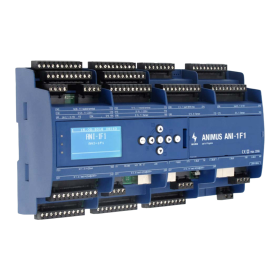
Fig. 1: Front view of ANI-1F1 with ANI-C control panel
1.1 Features
•
Standard compound controller with 3 compressors controlled by evaporation temperature
-
Compressor 1 constant (FC), compressors 2 and 3 controlled stepwise
-
Simple base load change
-
Monitoring of suction gas temperature
-
Oscillation protection function
-
Blocking time after compressor fault
-
Two-step load shedding and fast return flow
-
Operating hours counter for each compressor
-
Proactive oil return
•
LT compressor control after pumpdown
•
High and medium pressure control
•
Gas cooling fan control
•
Additional control circuits for:
-
Load shedding
-
Deheater
-
Fluid post-injection
-
Refrigerant monitoring
-
Heat recovery
-
Pressure monitoring
-
Control cabinet monitoring
•
Integrated relay outputs
•
CAN bus connection via patch cable and screw terminals
•
Fastening via top-hat rail
•
Connection to the Wurm system through a Wurm CAN communication bus (C-BUS) and
FRIGODATA XP
Accessories
•
Control panel (ANI-C)
ANI-1F1_V2.2.0_PI_2019-03_EN
refrigeration plants with compound and gas cooler con-
2
Subject to technical modifications
FRIGOLINK
ANI-1F1
1
Advertisement
Table of Contents

Related Manuals for WURM FRIGOLINK ANI-1F1


Summary of Contents for WURM FRIGOLINK ANI-1F1
-
Page 1: Ani-1F1
Integrated relay outputs • CAN bus connection via patch cable and screw terminals • Fastening via top-hat rail • Connection to the Wurm system through a Wurm CAN communication bus (C-BUS) and FRIGODATA XP Accessories • Control panel (ANI-C) ANI-1F1_V2.2.0_PI_2019-03_EN... -
Page 2: Table Of Contents
FRIGOLINK ANI-1F1 Contents ANI-1F1 ..........1 1.1 Features . -
Page 3: Safety Instructions
Wurm GmbH & Co. KG Elektronische Systeme. Keep these instructions ready to hand for quick reference and pass them on with the device if the product is sold. -
Page 4: Circuit Diagram
Any software versions not listed are special solutions for individual projects and are not described in detail in this document. This document automatically ceases to be valid if a new technical description is issued. Manufacturer: Wurm GmbH & Co. KG Elektronische Systeme, Morsbachtalstraße 30, D-42857 Remscheid For further information, see our website at www.wurm.de... -
Page 5: Input Circuit Diagram
FRIGOLINK ANI-1F1 1.3.1 Input circuit diagram 140 139 138 137 136 135 134 133 132 131 140 139 138 137 136 135 134 133 132 131 120 119 118 117 116 115 114 113 112 111 120 119 118 117 116 115 114 113 112 111 238 237 236 235 234 233 232 231 250 249 248 247 246 245 244 243 242 241 130 129 128 127 126 125 124 123 122 121... -
Page 6: Analogue Inputs Uin 1, 2
FRIGOLINK ANI-1F1 Terminal Digital input Potential Assignment DI 11 230V~ Fault CP 2 DI 12 230V~ Fault CP 3 DI 13 230V~ Fault LT CP DI 14 230V~ Fault min. refrigerant DI 15 230V~ Fault max. refrigerant DI 16 230V~ Fault LP compound DI 17 230V~... -
Page 7: Analogue Inputs S 1 - S 16
FRIGOLINK ANI-1F1 Analogue inputs S 1 - S 16 Terminal Sensor input Sensor type Assignment 161/162 Ts MT 163/164 T.pg MT 165/166 T.dsh LT 167/168 T.out 169/170 T.gc 1 171/172 T.gc 2 173/174 HR CO2 output 175/176 Medium HR output 177/178 Medium HR input 179/180... -
Page 8: Output Circuit Diagram
FRIGOLINK ANI-1F1 1.3.2 Output circuit diagram 120 119 118 117 116 115 114 113 112 111 238 237 236 235 234 233 232 231 238 237 236 235 234 233 232 231 250 249 248 247 246 245 244 243 242 241 250 249 248 247 246 245 244 243 242 241 140 139 138 137 136 135 134 133 132 131 130 129 128 127 126 125 124 123 122 121... -
Page 9: Digital Outputs (Ssr) V 1 - V 4
FRIGOLINK ANI-1F1 Contact arrange- Terminal Digital output Assignment ment NO contact K 10/ Not available 4(2)A@230V~ NO contact K 11 / Desuperheater oper- 4(2)A@230V~ ation NO contact K 12 / Not available 4(2)A@230V~ NO contact K 13 / Not available 4(2)A@230V~ NO contact K 14 / Control cabinet fan... -
Page 10: Communication Circuit Diagram
FRIGOLINK ANI-1F1 1.3.3 Communication circuit diagram 140 139 138 137 136 135 134 133 132 131 120 119 118 117 116 115 114 113 112 111 238 237 236 235 234 233 232 231 250 249 248 247 246 245 244 243 242 241 130 129 128 127 126 125 124 123 122 121 110 109 108 107 106 105 104 103 102 101 44 43 42 41... -
Page 11: Installing
FRIGOLINK ANI-1F1 Installing The module is designed for top-hat rail installation. The housing is also suitable for installation in fuse boxes or distribution switch cabinets. Modules can be positioned side by side without gaps. DANGER TO LIFE FROM ELECTRIC SHOCK AND/OR FIRE! WARNING •... -
Page 12: Dismantling
FRIGOLINK ANI-1F1 Dismantling 1. Insert a flat-tip screwdriver in the openings in the fastening catches. 2. Pull the two fastening catches away from the housing until they are heard to click. 3. Swivel the bottom of the module gently away from the top-hat rail and towards yourself. 4.
Need help?
Do you have a question about the FRIGOLINK ANI-1F1 and is the answer not in the manual?
Questions and answers