Table of Contents
Advertisement
Quick Links
Advertisement
Table of Contents

Subscribe to Our Youtube Channel
Related Manuals for LaMotte 6 Series


Summary of Contents for LaMotte 6 Series
- Page 1 CON 6/TDS 6 Meter Manual The LaMotte 6 Series...
- Page 2 WARNING! This set contains chemicals that may be harmful if misused. Read cautions on individual containers carefully. Not to be used by children except under adult supervision...
-
Page 3: Table Of Contents
CONTENTS Introduction ......Display & Keypad Functions ..... . Display . - Page 4 Error Messages......Specifications ......32-33 Accessories .
-
Page 5: Introduction
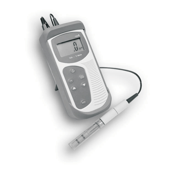
INTRODUCTION Thank you for purchasing the CON 6 Conductivity Meter or TDS 6 Total Dissolved Solids Meter. These economy microprocessor-based handheld meters deliver up to ±0.5% full-scale accuracy. It has a large custom LCD (Liquid Crystal Display) for clear and easy reading. The CON 6 measures Conductivity (µS/mS) and Temperature (°C) while the TDS 6 measures Total Dissolved Solids (TDS) and Temperature (°C). - Page 6 ° Conductivity/ Meter HOLD ENTER MODE...
-
Page 7: Display & Keypad Functions
DISPLAY & KEYPAD FUNCTIONS Display The meter has a large custom LCD that consists of 4-digit segments and operation annunciators for uS/mS for the CON 6 meter, or ppm/ppt for the TDS 6 meter, and °C (Temperature). Other annunciators include “HO” (when the HOLD function is activated) and “LO”... -
Page 8: Keypad
Keypad The CON 6 /TDS 6 meter has 6 buttons on the splash-proof keypad; ON/OFF, HOLD/ENTER, CAL, MODE, question buttons. Some buttons have several functions depending on the mode of operation. Powers on and shuts off the meter. Goes directly into the measurement mode when the meter is turned on. -
Page 9: Preparation
PREPARATION Inserting & Removing Rubber Boot To insert the meter into the rubber boot, slide the top of the meter into the rubber boot before pushing the bottom edges of meter down to set it into position. Lift up the stand at the back of meter for bench top applications if necessary. -
Page 10: Conductivity Electrode Information
Conductivity Electrode Information The CON 6/TDS 6 hand-held meter is supplied with a conductivity/TDS electrode with a BNC connector. This conductivity/TDS electrode comes with Stainless Steel rings, a cell constant of K = 1.0, and a built-in temperature sensor for Automatic Temperature Compensation (ATC). The specially designed Ultem-body housing has chemically resistant properties. -
Page 11: Connecting The Probe To Meter
Connecting the Probe to the Meter 1. To connect the electrode to the meter, align the connector slots with the posts of the meter socket and rotate the connector clockwise until it locks. 2. To remove, rotate the connector in a counter-clockwise direction until it unlocks, and slide the connector off the socket. -
Page 12: Turning The Meter On
Turning the Meter On When the meter is turned on, it will go through a series of displays that show the set-up parameters. For CON 6 ° µ pH % ° ° µ µ pptmV Measurement Mode For TDS 6 °... -
Page 13: Change Conductivity/Tds " Temperature Measurement Mode
4. Fourth screen shows [t 2.1%] which is the Temperature Coefficient. The meter can be customized with different Temperature Coefficient values from 0.0 to 3.0 %/°C in the Advance Set-up mode. Default value is 2.1 %/°C. 5. All LCD segments will light up for 2 seconds, and then advance into the measurement mode. -
Page 14: Calibration
CALIBRATION Important Information on Meter Calibration The meter has five measuring ranges. The meter can be calibrated at one po int in each of the five measuring ranges. If measurements are being taken in more than one range, each of the ranges were measurements are being made must be calibrated. -
Page 15: Preparing The Meter For Calibration
Preparing the Meter for Calibration Before starting calibration, be sure the meter is in the correct measurement mode. For best results, select a standard value close to the value of the sample that is being measured. Alternatively use a calibration solution value that is approximately 2/3 the full-scale value of the measurement range that is being used. -
Page 16: Selection Of Automatic Or Manual Calibration
Selection of Automatic or Manual Calibration This meter is capable of performing either automatic (CON 6 only) or manual calibration. In the automatic calibration mode, the meter (CON 6 only) automatically detects and verifies the appropriate known calibration standards solutions being calibrated before accepting these particular calibration standards as one of the calibration values in a specific measurement range. -
Page 17: Automatic Calibration (Conductivity)
Automatic Calibration (Conductivity) In the Automatic Calibration mode, the meter is capable of accepting a single-point calibration or up to 4 points for multi-point calibration with the maximum of 1 point per specific measurement range. For the automatic calibration standard values refer to Table 1. 1. -
Page 18: Manual Calibration (Conductivity Or Tds)
2. If the temperature (t °C) of the conductivity calibration solution is below 0 °C or above 50 °C (0°C < t °C > 50 °C), an error message “Err 2” will be displayed when performing the auto calibration, and meter will return to measurement mode. -
Page 19: Temperature Calibration
Temperature Calibration The conductivity electrode has a built-in temperature sensor for ATC. The temperature sensor is factory calibrated to the meter. Calibrate the sensor only if it is suspected that temperature errors that may have occurred over a long period of time or if the probe is a replacement probe. 1. -
Page 20: Measurement
MEASUREMENT The CON 6/TDS 6 meter is capable of taking measurements with automatic temperature compensation or manual temperature compensation. With Automatic Temperature Compensation (ATC) For ATC, make sure the phono jack of the probe is securely connected to the meter. The conductivity/TDS reading displayed will be compensated for according to the normalization temperature (20 °C or 25 °C) selected. -
Page 21: Taking Measurements
Taking Measurements 1. Rinse the probe with deionized or distilled water before use to remove any impurities adhering to the probe body. Shake or air dry. To avoid contamination or dilution of the sample, rinse the probe with a small volume of the sample liquid. -
Page 22: Hold Function
Auto-ranging Manual ranging: 0 - 20.00 uS/cm Manual ranging: 0 - 200.0 uS/cm µ µ µ µ Manual ranging: 0 - 200.0 mS/cm Manual ranging: 0 - 20.00 mS/cm Manual ranging: 0 - 2000 uS/cm NOTE: If the value of the solution being measured is higher than the range selected [Or] will appear on the primary display. -
Page 23: Advanced Set-Up Functions
ADVANCED SET-UP FUNCTIONS Advanced Set-up Overview The advanced set-up mode customizes the meter preferences and defaults. To enter the advanced set-up mode: 1. Make sure that the meter is turned off. 2. Press ON and MODE buttons simultaneously, holding both buttons for 2 seconds. - Page 24 Select Single Point Calibration. Choice of “Yes” or “No”. Default value is “Yes”. User reset to factory defaults. Choice of “Yes” or “No”. Default value is “no”. Overview of Advanced Set-Up Meter Off Press ON/OFF and MODE buttons simultaneously for 2 seconds, release MODE ON/OFF button first then release MODE key button a second later.
-
Page 25: Select Cell Constant
Meter Press ON/OFF and MODE buttons keys MODE simultaneously for 2 seconds, release Release ON/OFF button first then release MODE button a second later. A "StUP" indicator will appear for 1.5 seconds before showing the first menu. ° Overview of TDS 6 Set-Up Menu Select Cell Constant It is possible to select a cell constant of K = 1.0, 10, or 0.1. -
Page 26: Automatic Calibration (For Con 6)
Automatic Calibration (for CON 6) The automatic calibration allows the meter to be quickly calibrated to any of the four widely used conductivity calibration standards. For a list of calibration standards refer to Table 1. HOLD ENTER In the manual calibration mode, customized conductivity calibration standard can be used to calibrate this meter. -
Page 27: Temperature Coefficient
Temperature Coefficient The temperature coefficient is the amount of change in conductivity per degree of temperature; it is expressed in percent per °C. Entering the exact temperature coefficient of the solution being measured will accurately HOLD ENTER compensate the temperature for almost any solution. The temperature coefficient can be set between 0.0 and 3.0 % per °C. -
Page 28: Single-Point Calibration
Single-Point Calibration A single-point calibration refers to calibrating at one conductivity value that will be used for all 5 conductivity ranges. By selecting [no] to single-point calibration, a calibration for each conductivity range can be performed. HOLD ENTER 1. Enter Advanced Set-up. 2. -
Page 29: Probe Care And Maintenance
PROBE CARE AND MAINTENANCE Keep the conductivity probe clean. Rinse the probe twice before using. Gently swirl the probe in the solution while taking readings. Do not immerse the probe in oily solutions. For best accuracy, soak a dry probe for at least 5 to 10 minutes or longer before calibration. -
Page 30: Troubleshooting Guide
TROUBLESHOOTING GUIDE Problem Cause Solution Power on but a) Batteries not in a) Check that batteries no display place are in place and making good contact. b) Batteries not in correct polarity (+ and b) Reinsert batteries – position) with correct polarity. c) Weak batteries c) Replace batteries. -
Page 31: Error Messages
ERROR MESSAGES LCD Display Indicates Cause Solution “LO” Low battery Need new Clean battery indicator level batteries or contacts. appears. battery Replace batteries connection is with fresh ones, bad. noting polarity. Err 1 Conductivity Calibration Check the value calibration point is outside of the error the ±40%... -
Page 32: Specifications
If an error message appears, turning off the meter and turning it on again may eliminate the error message. Refer to diagram on right. µ If error persists, or the meter shows incorrect values, return the meter. For a complete diagram of the display see page 3. SPECIFICATIONS DESCRIPTIONS CON 6... - Page 33 SPECIFICATIONS DESCRIPTIONS CON 6 TDS 6 Temperature 0.0 to 3.0% / °C Coefficient Normalization 20.0 °C and 25.0 °C Temperature (selectable) Conductivity to TDS 0.4 to 1.0 Conversion factor Number of 5: Maximum 1 per calibration points range Auto- & Manual-ranging HOLD Function Auto Power Off...
-
Page 34: Accessories
ACCESSORIES Replacement Meter and Meter accessories Item Code CON 6, portable conductivity meter 5-0039-01 complete with conductivity probe of k=1.0 and case TDS 6, portable TDS meter complete 5-0037-01 with conductivity probe of k=1.0 and case Electrode, stainless steel 3 ring, 5-0106 Ultem body with ATC, BNC plug (for CON 6), cell constant = 1.0,... -
Page 35: Conductivity Theory
CONDUCTIVITY THEORY Conductivity is defined as the ability of a solution to conduct an electrical current, or the reciprocal of the solution’s ability to resist the current. The current is conducted by electrically charged particles called ions, which are present in almost all solutions. Different solutions have different kinds and amounts of ions. -
Page 36: Appendix 1: Calibration Tips
Conductivity measurements are very dependent on temperature. The ability of the ions to move through the solution, and conduct the current, is related to the temperature of the solution. As the temperature of the solution rises, the ions move more quickly through the solution, increasing the conductivity. As the temperature decreases the ions move more slowly and the conductivity decreases. -
Page 37: Appendix 2: Calculating The Tds Conversion Factor
APPENDIX 2: CALCULATING The TDS CONVERSION FACTOR The meter can be calibrated using TDS calibration standard solutions. The TDS value of the solution at a standard temperature, such as 25 °C, is required. To determine the conductivity-to-TDS conversion factor use the following formula: Factor = Actual TDS ÷... -
Page 38: Warranty
(6) months from the original purchase date. In the event that a defect is found during the warranty time frame, LaMotte Company agrees that it will be repaired or replaced without charge except for the transportation costs. -
Page 39: Return Of Items
LaMotte Company by calling 1-800-344-3100, faxing 1-410-778-6394, or emailing tech@lamotte.com. Often a problem can be resolved over the phone or by email. If a return of the meter is necessary, attach a letter with the return authorization number, meter serial number, a brief description of problem and contact information including phone &... - Page 40 LaMOTTE COMPANY Helping People Solve Analytical Challenges® PO Box 329 • Chestertown • Maryland • 21620 • USA 800-344-3100 • 410-778-3100 • Fax 410-778-6394 Visit us on the web at www.lamotte.com 626094-26/28 - 09/08...
Need help?
Do you have a question about the 6 Series and is the answer not in the manual?
Questions and answers