Table of Contents
Advertisement
Quick Links
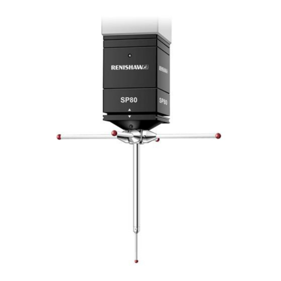
SP80 and SP80H installation and integration guide
www.renishaw.com
SP80 and SP80H installation and integration
guide
Document part number: H-1000-5212-05-B
This installation and integration guide is intended to assist OEM and Renishaw personnel in the initial installation, integration and use of the
Renishaw SP80 and SP80H ultra-high accuracy scanning probes. The SP80 and SP80H are quadrature output measurement probes that
provide class-leading performance, as well as the most flexible use of styli for maximum productivity.
This guide provides information on mechanical and electrical probe installation, system connections and interface options. If you intend to
handle probe interfacing yourself then details of probe signals, power requirements etc. can be found in the section
'system interconnection
and electrical
integration', although this will significantly increase the complexity of the integration process.
Issued 10 2019
1
Advertisement
Table of Contents

Subscribe to Our Youtube Channel
Related Manuals for Renishaw SP80


Summary of Contents for Renishaw SP80
- Page 1 Document part number: H-1000-5212-05-B This installation and integration guide is intended to assist OEM and Renishaw personnel in the initial installation, integration and use of the Renishaw SP80 and SP80H ultra-high accuracy scanning probes. The SP80 and SP80H are quadrature output measurement probes that provide class-leading performance, as well as the most flexible use of styli for maximum productivity.
-
Page 2: General Information
Renishaw distributor. Warranty Renishaw plc warrants its equipment for a limited period (as set out in our Standard Terms and Conditions of Sale) provided that it is installed exactly as defined in associated Renishaw documentation. Prior consent must be obtained from Renishaw if non-Renishaw equipment (e.g. interfaces and/or cabling) is to be used or substituted. Failure to comply with this will invalidate the Renishaw warranty. -
Page 3: Care Of Equipment
LDPE Outer box Corrugated fibreboard High density polyethylene HDPE Patents Features of the SP80 system and associated products, equipment and techniques are the subjects of one or more of the following patents and patent applications: CN100381776 EP1368615 IN309714 JP4062515 US6909983... -
Page 4: Product Compliance
Information to user (47 CFR 15.21) The user is cautioned that any changes or modifications not expressly approved by Renishaw plc or authorised representative could void the user's authority to operate the equipment. -
Page 5: Reach Regulation
SP80 and SP80H installation and integration guide www.renishaw.com REACH regulation Information required by Article 33﴾1﴿ of Regulation ﴾EC﴿ No. 1907/2006 ﴾“REACH”﴿ relating to products containing substances of very high concern (SVHCs) is available at: www.renishaw.com/REACH China RoHS Contact Renishaw plc or visit www.renishaw.com/ChinaRoHS... -
Page 6: System Requirements
CC6 counter card. NOTE: The SP80 and SP80H can be powered by either a connection to a Renishaw UCC S3 controller and UCC PI 80 interface, or an IU80 and CC6 counter card via a PC or an OEM specifically designed system. - Page 7 SP80 and SP80H system to avoid injury in the case of stylus breakage. Machine operators must be trained in the use and application of the SP80 and SP80H in the context of the machine it is fitted to before being allowed to operate that machine.
- Page 8 SP80 can be integrated in the following ways: Direct integration with Renishaw's UCC S3 controller (this requires the use of a UCC PI 80 interface) Using Renishaw's CC6 PCI counter card together with Renishaw's IU80 interpolator unit OEM designed counter card used with Renishaw's IU80 interpolator unit...
- Page 9 SP80 and SP80H installation and integration guide www.renishaw.com Probe connector pin-outs The electrical connections to and from the SP80 and SP80H are through the 15-way HDD connector at the top of the probe body. SP80 and SP80H probe connector pin-outs Function...
- Page 10 Connecting the IU80 interpolator unit The IU80 is connected to the SP80 by the machine cable and the short adaptor cable. The output of the IU80 is then transferred either to the Renishaw CC6 PCI counter card, or to an OEM controller via a Renishaw supplied unterminated cable.
- Page 11 IU80 features and LEDs Signal interpolation The IU80 divides the 4 micron periodic signals produced by the SP80 by a factor of 200. This gives a system resolution of 20 nm for each probe axis. Error signal generation The IU80 monitors the signals received from the SP80 probe to ensure that each axis readhead is functional. In the event of probe cable damage or unreliable probe signals, an error signal is latched and provides an output via pin 4 of the 26-way connector.
- Page 12 SP80 LED control The SP80 probe has a tri-colour LED which can be controlled by the user to act as a visual aid for measurement applications. The LED can be set to red, green or orange depending on the following inputs to pins 9 and 10 of the 26‐way ‘D' plug.
- Page 13 The standard SP80 / SP80H probe kit is supplied with a 250 mm long PL157 cable . This connects to the 15-way, high-density D-type connector on top of the SP80, through a slot in the KM80 (or KM6080), and is terminated in a Lemo connector which mates to the CMM machine cable.
- Page 14 SP80 and SP80H installation and integration guide www.renishaw.com Cable pin-outs (SP80 / SP80H > KM80 > KM6080 > M/C cable > IU80) Signal / connector 15-way HDD connector 14-way Lemo connector 15-way male D connector Vref Not connected Cos Z...
- Page 15 Connecting SP80 / SP80H using the SM80 The SM80 converts the output connector on the SP80 / SP80H to a Touchel connector on the rear face of the SM80. The Touchel connector is then designed to be connected directly to a standard PH10 system wiring scheme.
- Page 16 SP80 and SP80H installation and integration guide www.renishaw.com Cable pin-outs (SP80 / SP80H > SM80 > probe head cable > M/C cable > IU80) Signal / connector 14-way Touchel socket 14-way Lemo connector 15-way male D connector Vref Not connected...
- Page 17 SP80 and SP80H installation and integration guide www.renishaw.com Connecting SP80 / SP80H using UCC PI 80 The UCC PI 80 has different configuration layouts to provide an interface to CMM systems with three, four or five machine axes, whether brushed or brushless motors.
- Page 18 SP80 and SP80H installation and integration guide www.renishaw.com 3- or 4-axis CMM with brushless motors NOTE: See UCC BI installation guide (Renishaw part number H-1000-7602) for configuration instructions. Issued 10 2019...
- Page 19 SP80 and SP80H installation and integration guide www.renishaw.com 3- or 4-axis large CMM with motors requiring an analogue servo power amplifier Issued 10 2019...
- Page 20 SP80 and SP80H installation and integration guide www.renishaw.com 3-axis CMM with DC motors Issued 10 2019...
- Page 21 CC6 PCI counter card The IU80 conditions the SP80 / SP80H signal into an RS422 differential quadrature scale signal. This unit is required when a UCC S3 and UCC PI 80 is not used for the integration of the probe. The IU80 has a 15-way D input connector to accept the standard PH10 machine cable, and a 26-way D output connector, incorporating all axis outputs from the probe.
- Page 22 Not used Z DigA Z DigA Z DigB +12 V @ 250 mA max +5 V @ 1 A max Not used Shell Screen Shell For further information concerning the CC6 system please ask your local Renishaw contact. Issued 10 2019...
- Page 23 Probe and IU80 power supply The IU80 must be provided with two power supplies. +9 V to +18 V @ 300 mA max to supply the SP80 probe and +4.75 V to 5.25 V @ 1 A max to supply the IU80.
- Page 24 Connecting SP80 / SP80H to IU80 and OEM counter card Description SP80 / SP80H probe (shown for mounting to CMM via KM80) PL157 - SP80 to Lemo adaptor cable PLM6 / 7 / 8 / 9 - standard machine cable...
- Page 25 Probe and IU80 power supply The IU80 must be provided with two power supplies. +9 V to +18 V @ 300 mA max to supply the SP80 probe and +4.75 V to 5.25 V @ 1 A max to supply the IU80.
- Page 26 SP80 and SP80H installation and integration guide www.renishaw.com IU80 output signal format The signals produced by IU80 are in EIA-422-A differential square wave format and in quadrature for each probe axis. The sign definition for the signals is a positive count when DigA leads DigB.
-
Page 27: Air Supply
The SP80 and SP80H probes are supplied with a blanked off air purge hole. If the probe is to be operated in an environment where oil mist or other heavy vapours are present it is essential that an air supply is used to maintain positive purging of any contamination from the interior of the probe. - Page 28 +3 °C 5 mg/m *NOTE: The exact values are dependent on the inherent characteristics of the air pipe between the air filters and the SP80 / SP80H. Higher flow rates should be avoided as this could impair metrology. Please ask the installer for the specification.
- Page 29 SP80 and SP80H installation and integration guide www.renishaw.com Dew point indications and maintenance instructions Grain colour Causes Solutions Blue / green Normal operation. No action required. Pink / yellow Water and oil flow into membrane air dryer. 1) Check and replace filters if necessary.
- Page 30 SP80 and SP80H installation and integration guide www.renishaw.com Installing SP80 / SP80H air purge option Install the air purge connector by following the steps detailed below: 1. Remove screw as indicated. 2. Screw the supplied air fitting (P-MA01-0043) into the hole.
- Page 31 SP80 and SP80H installation and integration guide www.renishaw.com 3. Fit the air pipe to the air fitting. Issued 10 2019...
- Page 32 Attaching the KM80 quill adaptor plate Mounting the SP80 and SP80H on the CMM via the KM80 is the recommended method due to its inherent stiffness, as well as the reduced overall Z length when compared to the alternative mounting options (KM6080 or SM80). The KM80 has the same mechanical footprint as the PH10MQ ﴾80 mm ×...
- Page 33 SP80 and SP80H installation and integration guide www.renishaw.com Alternative quill adaptor plates Attaching the KM6080 quill adaptor plate The KM6080 ﴾60 mm × 60 mm﴿ is attached to the quill using four screws. It is important to orientate the KM6080 on the quill such that the probe is aligned facing forwards (with the LED facing towards the front of the CMM).
- Page 34 SP80 and SP80H installation and integration guide www.renishaw.com Aligning the KM80, KM6080 or SM80 for use with the SCP80(V) To ensure satisfactory operation with both SCP80 and SCP80V during the change cycle, the KM80, KM6080 quill adaptor plate or SM80 shank mount must be aligned to the CMM axes within the limits shown.
- Page 35 The SP80 and SP80H probe bodies have the female half of the kinematic joint incorporated in its top plate. The male half of the kinematic joint is incorporated in the KM80, the KM6080 and the SM80. To attach the probe to the quill adaptor plate proceed as follows: 1.
- Page 36 SP80 / SP80H body The SH80 incorporates the male half of a magnetic kinematic joint that connects to the female half of the joint on the bottom of both the SP80 and SP80H probe body. The SH80 carries M5 styli, and has a 5-way centre design that can be rotationally adjusted for infinite angle position of the stylus.
- Page 37 SP80 and SP80H installation and integration guide www.renishaw.com Mounting styli on the SH80 and styli orientation Mounting styli on the SH80 It is recommended that the SH80 is removed from the probe body when attaching styli. M5 stylus arrangements are directly screwed into the 5-way cube on the SH80. Where required, use step down adaptors to smaller thread styli, or select cubes and knuckles to create the required cluster.
-
Page 38: Installation Procedure
SP80 and SP80H installation and integration guide www.renishaw.com Fitting the SCP80 / SCP80V to the MRS / MRS2 rack system Fitting SCP80 to the MRS rail The SCP80 change ports can be fixed to an MRS or MRS2 rack system. It is recommended that they are attached to the MRS / MRS2 rail using the following procedure, where it is assumed that the MRS / MRS2 rack system is correctly installed. - Page 39 SP80 and SP80H installation and integration guide www.renishaw.com Alignment of the SCP80(V) to the CMM axes Alignment of the SCP80 to the CMM axes The alignment of the SCP80 to the CMM axes should be checked to be within the limits shown below.
- Page 40 The SCP80(V) ports should have previously been fitted to the MRS rail (or extrusion) and aligned to the CMM axes The SP80 / SP80H probe should have been correctly installed, aligned and fitted with a suitable M5 stylus The probe and stylus should have been calibrated and made ready to take single point measurements NOTE: The examples given here assume that the MRS / SCP80 rack system is aligned to the X-axis of the CMM, being along the rear of the working area.
- Page 41 Store the datum then assign it, and the port, an identification number. METHOD 2 (non-preferred) This method is simpler to use and merely uses a constant ZOFFSET value which will allow any stylus configuration within the SP80 carrying range of 33 g to 500 g to be docked.
- Page 42 SP80 and SP80H installation and integration guide www.renishaw.com Put down and pick up routines for SH80 The recommended pick up and put down routines are detailed below and consist of driving sequentially through four positions. These apply to both SP80 and SP80H.
- Page 43 SP80 and SP80H installation and integration guide www.renishaw.com Pick up routine for SH80 / SCP80 or SCP80V Move description Offsets orientated to the Offsets orientated to the Offsets orientated to the probe axes probe axes probe axes Move to the clearance position...
- Page 44 SP80 and SP80H installation and integration guide www.renishaw.com Put down and pick up routine for SH80K with SP80 Put down routine for SH80K and SP80 Move description Offsets orientated to the Offsets orientated to the Offsets orientated to the probe axes...
- Page 45 SP80 and SP80H installation and integration guide www.renishaw.com Put down and pick up routine for SH80K with SP80H Put down routine for SH80K and SP80H Move description Offsets orientated to the Offsets orientated to the Offsets orientated to the probe axes...
-
Page 46: Modes Of Operation
Single point measurement mode The following are methods that can be used for taking single point measurements using a calibrated SP80 or SP80H. OEMs are advised to evaluate each of these to determine the best solution for their own system. - Page 47 SP80 and SP80H installation and integration guide www.renishaw.com Threshold methods There are two types of threshold method as described below. Type 1 takes data whilst driving the probe onto the part to a pre-set deflection threshold, whilst type 2 takes data whilst backing off to the pre-set deflection threshold.
-
Page 48: Maximising Performance
Maximising performance Calibration The probe and stylus must be calibrated correctly. Renishaw has extensive experience of scanning and offers support and advice on calibration algorithms and control software suited to SP80. Please contact Renishaw for further information. Probe deflection Scanning deflections should be kept small, as the machine settings and application will allow loads on the probe, stylus and CMM quill to be minimised. - Page 49 Of particular interest to SP80 and SP80H users is M5 styli section. This details not only an extensive range of M5 styli that are compatible with the SP80 and SP80H, but also includes a complete range of carbon fibre extension bars of 11 mm or 20 mm diameter, and up to 500 mm long.
- Page 50 SP80 and SP80H installation and integration guide www.renishaw.com Ball materials available with Renishaw styli Ruby The industry standard and the optimum stylus ball material for a vast majority of measurement applications, ruby is one of the hardest known materials. Synthetic ruby is 99% pure aluminium oxide, which is grown into crystals ﴾or ‘boules'﴿ at 2000 °C using the Verneuil process.
- Page 51 Renishaw GF is ideal for maximising stiffness while giving very low mass for styli above 50 mm in length. It is the optimum stem material for high accuracy strain gauge technology probes with excellent vibration damping characteristics and negligible co-efficient of thermal expansion.
- Page 52 SP80 and SP80H maintenance The SP80 / SP80H probe is a serviceable part. In the event of a problem, please contact your supplier for assistance. Following the simple maintenance procedures given below will prolong the operational life and continued high performance of the system.
- Page 53 SP80 and SP80H installation and integration guide www.renishaw.com SP80 and SP80H system integration notes The following sections identify various probe characteristics that customers will need to be aware of during the integration of the SP80 / SP80H system. Issued 10 2019...
-
Page 54: Return To Zero
SP80 and SP80H installation and integration guide www.renishaw.com Return to zero The probe has a nominal absolute centre position where the functions of stylus configuration and probe orientation cause it to rest. Because of small amounts of internal friction, when the probe is displaced from this zero point, the stylus will not return to exactly the same point on the scale and the axis deflection readings will show a different value. - Page 55 The procedure for this is to remove the SH80 stylus holder from the SP80 /SP80H probe body and permit the probe mechanism to return to its zero reference position; when the probe is in this position the scales within the head should be referenced ﴾set to 0﴿. This ‘null' position should be recorded.
- Page 56 Probe inertia Due to the inertia of the SP80 / SP80H motion system high CMM accelerations may cause non-contact probe deflections to exceed thresholds set within the control algorithms; this inertia will vary according to the stylus arrangement. Issued 10 2019...
- Page 57 Renishaw plc +44 (0)1453 524524 New Mills, Wotton-under-Edge, +44 (0)1453 524901 Gloucestershire, GL12 8JR United Kingdom www.renishaw.com/cmmsupport For worldwide contact details, please visit our main website at www.renishaw.com/contact Issued 10 2019...
Need help?
Do you have a question about the SP80 and is the answer not in the manual?
Questions and answers