Table of Contents
Advertisement
Quick Links
Instructions
TDS6UP, TDS7UP, and CSA7UP Option CPU
Upgrade Kit
071-1244-00
Warning
The servicing instructions are for use by qualified
personnel only. To avoid personal injury, do not
perform any servicing unless you are qualified to
do so. Refer to all safety summaries prior to
performing service.
www.tektronix.com
*P071124400*
071124400
Advertisement
Table of Contents

Related Manuals for Tektronix TDS6UP


Summary of Contents for Tektronix TDS6UP
- Page 1 Instructions TDS6UP, TDS7UP, and CSA7UP Option CPU Upgrade Kit 071-1244-00 Warning The servicing instructions are for use by qualified personnel only. To avoid personal injury, do not perform any servicing unless you are qualified to do so. Refer to all safety summaries prior to performing service.
- Page 2 Copyright © Tektronix, Inc. All rights reserved. Tektronix products are covered by U.S. and foreign patents, issued and pending. Information in this publication supercedes that in all previously published material. Specifications and price change privileges reserved. Tektronix, Inc., P.O. Box 500, Beaverton, OR 97077...
-
Page 3: Service Safety Summary
Use Care When Servicing With Power On. Dangerous voltages or currents may exist in this product. Disconnect power, remove battery (if applicable), and disconnect test leads before removing protective panels, soldering, or replacing components. To avoid electric shock, do not touch exposed connections. TDS6UP, TDS7UP, and CSA7UP Option CPU Upgrade Kit... - Page 4 Service Safety Summary TDS6UP, TDS7UP, and CSA7UP Option CPU Upgrade Kit...
-
Page 5: Kit Description
Required tools and equipment Part number Screwdriver handle 620-440 T-20 Torx tip 640-250 T-15 Torx tip 640-247 Standard tool inch flat-bladed screwdriver #0 Phillips screwdriver Standard tool Standard tool inch open-end wrench TDS6UP, TDS7UP, and CSA7UP Option CPU Upgrade Kit... -
Page 6: Kit Parts List
BRACKET; CD- - ROM, REAR DRIVE BAY CHASSIS, 0.035 CRS 1 ea 020- - 2349- - XX SOFTWARE KIT; LICENSE CERTIFICATE,O/S EASY RESTORE,CERTIFICATE AUTHENTIC- ITY,WIN98 RESTORE CD Figure 1: CPU upgrade kit parts TDS6UP, TDS7UP, and CSA7UP Option CPU Upgrade Kit... -
Page 7: Installation Instructions
Installation Instructions This section contains all procedures needed to install TDS6UP, TDS7UP, or CSA7UP Option CPU in the TDS6000, TDS7000, and CSA7000 Series instruments. These instructions are for personnel who are familiar with servicing the product. If you need further details for disassembling or reassembling the product, refer to the appropriate product manual. -
Page 8: Procedures For External Modules
Procedures for External Modules The following procedures are found here and are listed in the order presented. H Line Cord H Trim (all) H Bottom cover H Left and Right covers TDS6UP, TDS7UP, and CSA7UP Option CPU Upgrade Kit... - Page 9 AC power connector. 6. Reinstallation: Do in reverse step 5 to reinstall the line cord. AC power cord connector AC power cord Power Line fuses switch Line fuse holder Figure 2: Line cord removal TDS6UP, TDS7UP, and CSA7UP Option CPU Upgrade Kit...
- Page 10 Slide the side trim panels towards the rear of the instrument allowing the tabs to clear the cover openings, and then pull out to remove the panels from the instrument. 6. Reinstallation: Do in reverse steps 2 through 5 to reinstall the appropriate trim. TDS6UP, TDS7UP, and CSA7UP Option CPU Upgrade Kit...
- Page 11 To remove the trim ring, slide the flat end of a soldering aid into the side slot on the trim ring. Press in, and then lift up to hook it underneath. Then pry it up. Figure 3: Trim removal TDS6UP, TDS7UP, and CSA7UP Option CPU Upgrade Kit...
- Page 12 Remove the bottom cover from the instrument. 3. Reinstallation: Do steps a and b in reverse to reinstall the bottom cover. Bottom cover T-15 Torx screw (4) Figure 4: Bottom cover removal TDS6UP, TDS7UP, and CSA7UP Option CPU Upgrade Kit...
- Page 13 CAUTION. Take care not to bind or snag the covers on the internal cabling of the instrument as you remove or install. 3. Reinstallation: Do in reverse steps a through c to reinstall the cabinet covers. TDS6UP, TDS7UP, and CSA7UP Option CPU Upgrade Kit...
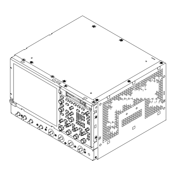
- Page 14 Installation Instructions All left and right cover mounting holes are indicated as shown. Left side cover T-15 Torx screw (11) Right side cover Figure 5: Cover removal TDS6UP, TDS7UP, and CSA7UP Option CPU Upgrade Kit...
- Page 15 Installation Instructions Left side cover Right side cover T-15 Torx screw Figure 6: Cover removal TDS6UP, TDS7UP, and CSA7UP Option CPU Upgrade Kit...
-
Page 16: Procedures For Internal Modules
Internal Modules, Figure 7, on page 15. Additional modules to be removed: WARNING. Remove the line cord before removing the covers from the instrument. H Trim (all) H Bottom cover H Left and Right covers TDS6UP, TDS7UP, and CSA7UP Option CPU Upgrade Kit... - Page 17 3. Orient the instrument: Set the instrument so that the bottom is down on the work surface and the top panel is facing you. a. Remove the two T-15 Torx screws that secure the floppy disk drive assembly into the front chassis. TDS6UP, TDS7UP, and CSA7UP Option CPU Upgrade Kit...
- Page 18 Grasp the front edge of the NLX board assembly and pull up on the assembly to disconnect the Riser Adapter from the Processor board edge connector. Remove the NLX board assembly from the instrument. TDS6UP, TDS7UP, and CSA7UP Option CPU Upgrade Kit...
- Page 19 Remove the two T-15 Torx screws that secure Riser Adapter board to the NLX support bracket. c. Disconnect the ribbon cable connectors from the floppy drive, hard drive, and CD drive. TDS6UP, TDS7UP, and CSA7UP Option CPU Upgrade Kit...
- Page 20 Floppy drive cable Hard drive cable connector Riser adapter board T- - 15 Torx J510 screw (2) CD drive cable connector NLX support bracket Figure 9: Riser adapter and NLX board removal TDS6UP, TDS7UP, and CSA7UP Option CPU Upgrade Kit...
- Page 21 1. Reinstall the CD drive, riser adapter, and NLX board assembly (refer to page 18). 2. Reinstall left and right covers (refer to page 11). 3. Reinstall the bottom cover (refer to page 10). TDS6UP, TDS7UP, and CSA7UP Option CPU Upgrade Kit...
-
Page 22: Verify Operation
8. Check that Memory lists the correct amount of RAM. 9. Click the TekScope button on the Windows toolbar to display the instrument application. This completes the verification of the NLX board assembly in your instrument. TDS6UP, TDS7UP, and CSA7UP Option CPU Upgrade Kit... - Page 23 Installation Instructions g End of document g TDS6UP, TDS7UP, and CSA7UP Option CPU Upgrade Kit...
Need help?
Do you have a question about the TDS6UP and is the answer not in the manual?
Questions and answers