Advertisement
Table of Contents
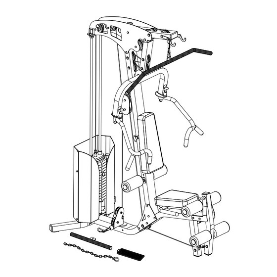
BLACKCOMB HOME GYM, 150LBS. WEIGHT STACK
BLACKCOMB HOME GYM, 150LBS. WEIGHT STACK
NLMGBC150
OVERALL DIMENSIONS: 61.5"L X 48"W X 83"H
9 APRIL 2020
Assembly INSTRUCTIONS
BOLT SIZE
1
4
1
2
3
4
1
1
1- 4
1
1- 2
3
1- 4
2
1
2- 4
1
2- 2
3
2- 4
3
1
3- 4
1
3- 2
3
3- 4
4
1
4- 4
1
4- 2
3
4- 4
5
1
5- 4
1
5- 2
3
5- 4
6
Keep This For Warranty
NLMGBC150
LOT:
1-866-420-4560
Northern Lights Fitness
Products Inc.
MADE IN CANADA
Specification
Weight=391.8 lbs
Packed in 5 Boxes
:32.5"x28.5"x13.5"
Box 1
:7.24 ft³
:96.8 Lbs
:74"x23.5"x9"
Box 2
:9.06 ft³
:145 Lbs
:11.75"x5.25"x5.25"
Box 3,4,5
:0.187 ft³
:(Each) 50 Lbs
Advertisement
Table of Contents

Related Manuals for Northern Lights BLACKCOMB HOME GYM


Summary of Contents for Northern Lights BLACKCOMB HOME GYM
- Page 1 BLACKCOMB HOME GYM, 150LBS. WEIGHT STACK ASSEMBLY INSTRUCTIONS BOLT SIZE 1- 4 1- 2 1- 4 2- 4 2- 2 2- 4 3- 4 3- 2 3- 4 4- 4 4- 2 4- 4 5- 4 5- 2 5- 4...
- Page 2 Parts List Item Item Part QTY. Box/Bag# Part QTY. Box/Bag# Main Upright Box 2 3/8" x 1" Bolt Bag 1 3/8" x 1-3/4" Bolt Bag 1 Lower Frame Box 2 Top Assembly Box 2 3/8" x 2-3/4" Bolt Bag 1 3/8"...
- Page 3 Page:-3 of 9...
- Page 4 NOTE: Leave all bolt connections untightened until weight stack assembly is in position. O O O 1. Bolt Rear Base (9) to Lower Frame (2) using bolts shown and four washers. 2. Loosely bolt two Lower Plates (4) to Lower Frame (2) using bolting shown. 3.
- Page 5 Optional: Add 1/2" Washer on both sides to avoid play in Arm 7. With a helper, loosely bolt the Main Upright (1) to the Lower Plates (4). 8. Slide the two Guide Rods (15) into the holes in the rear base. Slide down Weight Stack Supports (30) and Rubber Bumpers (AG) to the base of guide rods.
- Page 6 15. Start installation of the Top Cable (AU) at the top/ front 3-1/2" Pulley (AL) and Lat Bar Hooks(R&L) (20) using the bolting & spacers shown.Take care to keep the cable in the pulley grooves. 16. Continue installing the Top Cable (AU) and 3-1/2"...
- Page 7 Fig:1 Fig:2 17. Connect Top Cable (AU) and Lower Cable (AV) using two Pulley Brackets (19) and bolting shown in the detail (Fig:1). 18. Continue Lower Cable (AV) installation using bolting & Pulley Spacers (AB &AC) as shown in the details (Fig:2 & Fig:3).Once cables are installed, tighten all bolts. Fig:3 Page:-7 of 9...
- Page 8 19. Complete the installation of the Top Cable (AU) by threading the end of the cable into the Selector Rod (17) until slackness in the cables is removed.Tighten the jam nut against the Jam Nut Selector Rod. Periodic cable tightening may be required.
- Page 9 Aucune autre garantie n’a été faite ou Lights product. Northern Lights shall not be sera faite de la part de Northern Lights en ce qui responsible for injury, loss of use of the product, concerne tout produit de Northern Lights ou son inconvenience, loss or damage to personal opération, réparation ou échange.
Need help?
Do you have a question about the BLACKCOMB HOME GYM and is the answer not in the manual?
Questions and answers