
Related Manuals for Freemotion Reflex i11.9


Summary of Contents for Freemotion Reflex i11.9
- Page 1 Freemotion i11.9 Incline Trainer Assembly Manual: USE THIS assembly guide when machine ships in 5 pieces...
-
Page 2: Before You Begin
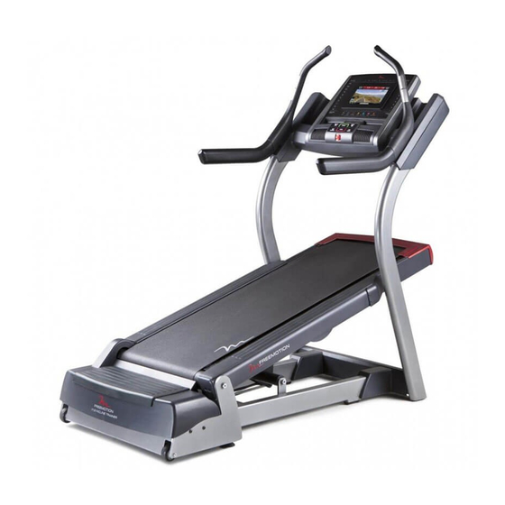
BEFORE YOU BEGIN Thank you for selecting the revolutionary after reading this manual, please see the back cover FREEMOTION i11.9 INCLINE TRAINER. The i11.9 of this manual. To help us assist you, note the product ® INCLINE TRAINER provides an impressive selection model number and serial number before contacting us. -
Page 3: Part Identification Chart
PART IDENTIFICATION CHART Use the drawings below to identify small parts used for assembly. The number in parentheses below each draw- ing is the key number of the part, from the PART LIST near the end of this manual. The number following the key number is the quantity used for assembly. - Page 4 ASSEMBLY • Assembly requires two persons. • Assembly requires the following tools: one 3/8" hex key • Place all parts in a cleared area and remove the packing materials. Do not dispose of the packing one 7/32" hex key materials until you finish all assembly steps. one Phillips screwdriver • To identify small parts, see page 7.
- Page 5 3. Partially tighten six 1/2" x 1" Screws (35) with four 1/2" Split Washers (49) and two 1/2" Star Washers (83) through the bracket near the right Upright (93) and into the Base Frame (56) as shown; do not tighten the Screws yet.
- Page 6 6. Set the console assembly on the Upright (93). Be care- ful not to pinch any wires. Make sure that the ends of Console Assembly the Console Crossbar (110) are inserted into the ends of the Uprights. Start two 3/8" x 2 1/2" Bolts (61) with two 3/8" Flat Washers (78) and two 3/8"...
- Page 7 9. Connect the pulse wires from the Left and Right Handrail Assemblies (112, 113) to the pulse wires from the Console (103). Insert the included ties through the tie blocks attached to the back of the Console Base (109). Loop the ties around the pulse wires, Upright Wire (116), and TV Cable (130) and tighten the ties around the wires.
- Page 8 12. See page 14 and plug in the power cord. Next, see page 17 and turn on the power. Then, press the % Grade Incline button numbered 30. 13. Press the Upright Cover (114) onto the lower end of the Upright (93) until the Upright Cover snaps into place.
Need help?
Do you have a question about the Reflex i11.9 and is the answer not in the manual?
Questions and answers