Table of Contents
Advertisement
www.iconfitness.com
Model No. FMSY9012.0
USER’'S MANUAL
Serial No.
Write the serial number in the space
above for reference.
Serial Number
Decal
ACTIVATE YOUR
WARRANTY
To register your product and
activate your warranty today,
go to www.iconservice.com/
registration.
CUSTOMER CARE
For service at any time, go to
www.iconservice.com.
Or call 1-800-999-3756
Mon.––Fri. 6 a.m.––6 p.m. MT
Sat. 8 a.m.––4 p.m. MT
Please do not contact the store.
CAUTION
Read all precautions and instruc-
tions in this manual before using
this equipment. Keep this manual
for future reference.
Advertisement
Chapters
Table of Contents

Related Manuals for Freemotion 1020 SY


Summary of Contents for Freemotion 1020 SY
- Page 1 www.iconfitness.com Model No. FMSY9012.0 USER’’S MANUAL Serial No. Write the serial number in the space above for reference. Serial Number Decal ACTIVATE YOUR WARRANTY To register your product and activate your warranty today, go to www.iconservice.com/ registration. CUSTOMER CARE For service at any time, go to www.iconservice.com.
-
Page 2: Table Of Contents
If a decal is missing or illegible, see the front cover of this manual and request a free replacement decal. Apply the decal in the location shown. Note: The decal(s) may not be shown at actual size. FREEMOTION is a registered trademark of ICON IP, Inc. -
Page 3: Important Precautions
IMPORTANT PRECAUTIONS WARNING: To reduce the risk of serious injury, read all important precautions and instructions in this manual and all warnings on your weight system before using your weight system. ICON assumes no responsibility for personal injury or property damage sustained by or through the use of this product. - Page 4 STANDARD SERVICE PLANS...
-
Page 5: Before You Begin
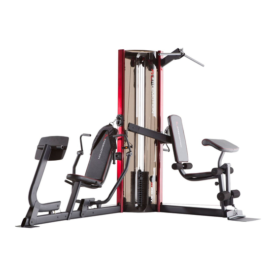
Thank you for selecting the versatile FREEMOTION ® after reading this manual, please see the front cover 1020 SY weight system. The weight system offers of this manual. To help us assist you, note the product an impressive array of weight stations designed model number and serial number before contacting us. -
Page 6: Part Identification Chart
PART IDENTIFICATION CHART Use the drawings below to identify the small parts needed for assembly. The number in parentheses below each drawing is the key number of the part, from the PART LIST near the end of this manual. Note: If a part is not in the hardware kit, check to see if it has been preassembled. - Page 7 M10 x 107mm Bolt Set (104) M10 x 20mm Screw (101) M10 x 59mm Bolt Set (115) M10 x 45mm Bolt (95) M10 x 45mm Hex Bolt (112) M10 x 50mm Bolt (102) M6 x 65mm Screw (106) M10 x 55mm Bolt (82) M6 x 40mm Screw (91) M10 x 65mm Bolt (85) M6 x 16mm...
-
Page 8: Assembly
ASSEMBLY •• To hire an authorized service technician to •• To identify small parts, see page 6. assemble this product, call 1-800-445-2480. •• In addition to the included tool(s), assembly •• Assembly requires two persons. requires the following tool(s): one Phillips screwdriver ••... - Page 9 2. Identify the Short Base (17) and the Weight Stack Base (109). Orient both parts as shown. Attach the Short Base (17) to the Weight Stack Base (109) with two M10 x 68mm Bolts (98), two M10 Washers (93), and an M10 Locknut (84); do not tighten the Bolts yet.
- Page 10 4. Identify the Right and Left Uprights (2, 14). Orient both parts as shown. Attach the Left Upright (14) to the Short Base (17) with two M10 x 115mm Bolts (97), four M10 Washers (93), and two M10 Locknuts (84); do not tighten the Bolts yet.
- Page 11 6. Orient the Weight Guides (29) so that the indi- cated holes are in the locations shown. Attach a Weight Guide (29) to the Weight Stack Base (109) with an M10 x 65mm Bolt (85), two M10 Washers (93), a 13mm Spacer (86), and an M10 Locknut (84);...
- Page 12 8. Orient the Weight Stack Top (13) as shown. Set the Weight Stack Top on the Weight Guides (29). Attach the Weight Stack Top (13) to the Right and Left Uprights (2, 14) with four M10 x 68mm Bolts (98), four M10 Washers (93), and two M10 Locknuts (84);...
- Page 13 10. Using a plastic bag to keep your fingers clean, apply some of the included grease to an M10 x 95mm Bolt (83). Attach the Leg Press Frame (5) to the Long Base (1) with the M10 x 95mm Bolt (83) and an M10 Locknut (84).
- Page 14 12. Identify the Right and Left Press Arms (11, 12) and the Press Arm Bracket (25). Orient the parts as shown. Attach the Right and Left Press Arms (11, 12) to the Press Arm Bracket (25) with three M10 x 70mm Bolts (99) and three M10 Locknuts (84);...
- Page 15 14. Apply grease to an M10 x 59mm Bolt Set (115). Attach the Left Press Handle (10) to the Left Press Arm (12) with the M10 x 59mm Bolt Set (115). Attach the Right Press Handle (9) to the Right Press Arm (11) in the same way.
- Page 16 16. Attach the Right Seat Frame (4) to the Right Upright (2) with two M10 x 68mm Bolts (98) and two M10 Washers (93); do not tighten the Bolts yet. 17. Attach the Right and Left Seat Handles (8, 32) to the Right Seat Frame (4) with two M10 x 117mm Bolts (89) and two M10 Locknuts (84).
- Page 17 18. Attach the Lat Bar Bracket (15) to the Left Upright (14) with two M10 x 68mm Bolts (98) and two M10 Washers (93). 19. See the CABLE DIAGRAMS starting on page 41 to identify the cables. Locate Cable B (64). Hold the ends of Cable Wire B near the center of the Butterfly Arm (23) as Ties...
- Page 18 20. While a second person holds the Butterfly Arm (23) near the Left Upright (14), insert the loop of Cable B (64) through the hole in the Left Upright. Attach the Butterfly Arm (23) to the Left Upright (14) with two M10 x 68mm Bolts (98), two M10 116 84 Washers (93), two 48mm Spacers (81), an M10 Large Washer (116), and an M10 Locknut (84);...
- Page 19 23. Route Cable B (64) over two Pulleys (46). Then, insert the Pulleys into the Left Upright (14). Make sure that Cable B is not twisted. Attach the Pulleys (46) with an M10 x 70mm Bolt (99) and an M10 Locknut (84). 24.
- Page 20 25. Attach the Left Seat Frame (18) to the Short Base (17) with two M10 x 115mm Bolts (97), four M10 Washers (93), and two M10 Locknuts (84); do not tighten the Bolts yet. 26. Attach the Left Seat Frame (18) to the Butterfly Arm (23) with two M10 x 20mm Screws (101).
-
Page 21: M10 X 107Mm Bolt
27. Apply grease to an M10 x 107mm Bolt Set (104). Attach the Leg Lever (20) to the Left Seat Frame (18) with the M10 x 107mm Bolt Set (104). Grease 28. See the CABLE DIAGRAMS starting on page 41 to identify the cables. Locate Cable C (65). - Page 22 30. Route Cable C (65) over a Pulley (46). Attach the Pulley (46) and a Cable Trap (49) to the Left Upright (14) with an M10 x 45mm Bolt (95) and an M10 Locknut (84). Make sure that the Cable Trap is oriented as shown. 49 46 31.
- Page 23 32. Route Cable C (65) over a Pulley (46). Attach the Pulley (46) and a Cable Trap (49) to the Left Upright (14) with an M10 x 45mm Bolt (95) and an M10 Locknut (84). Make sure that the Cable Trap is oriented as shown. 46 84 33.
- Page 24 34. Insert a Pulley (46) into the loop of Cable B (64). Attach the Pulley (46), a Cable Trap (49), and two Half Guards (47) to the U-bracket (27) with an M10 x 50mm Bolt (102) and an M10 Locknut (84). Make sure that the Cable Trap and the Half Guards are oriented as shown.
- Page 25 36. Route Cable D (66) under a Pulley (46). Attach the Pulley (46), a Cable Trap (49), and two Half Guards (47) to the first set of holes in a U-bracket (27) with an M10 x 50mm Bolt (102) and an M10 Locknut (84). Make sure that the Cable Trap and the Half Guards are oriented as shown.
- Page 26 39. Route Cable D (66) over a Pulley (46). Attach the Pulley (46) to the Left Upright (14) with an M10 x 45mm Bolt (95) and an M10 Locknut (84). 40. Route Cable D (66) through the bracket on the Weight Stack Top (13) and over a Pulley (46).
-
Page 27: 42. See The Cable Diagrams Starting On Page
42. See the CABLE DIAGRAMS starting on page 41 to identify the cables. Locate Cable E (67). Route Cable E through the Long Base (1) as shown. Then, insert a Pulley (46) into the Long Base over Cable E. Attach the Pulley (46) with an M10 x 65mm Bolt (85), two M10 Washers (93), two 13mm Spacers (86), and an M10 Locknut (84). -
Page 28: Under Cable D (66)
44. Insert a Pulley (46) into the Leg Press Frame (5) under Cable E (67). Attach the Pulley (46) with an M10 x 65mm Bolt (85), two M10 Washers (93), two 13mm Spacers (86), and an M10 Locknut (84). 67 46 See the inset drawing. - Page 29 47. Route Cable E (67) through the bracket on the Long Base (1). Attach a Pulley (46) and two Half Guards (47) to the bracket on the Long Base (1) with an M10 x 45mm Bolt (95) and an M10 Locknut (84). Make sure that the Half Guards are oriented as shown.
-
Page 30: Attach The Pulley (46) With An M10 X 115Mm Bolt
50. Locate Cable A (63). Route Cable A through the Leg Lever (20) and the Left Seat Frame (18). Insert a Pulley (46) into the Leg Lever (20) over Cable A (63). Attach the Pulley (46) with an M10 x 45mm Bolt (95) and an M10 Locknut (84). - Page 31 53. Route Cable A (63) over a Pulley (46). Attach the Pulley (46), a Cable Trap (49), and two Half Guards (47) to the third set of holes in two Pulley Plates (26) with an M10 x 50mm Bolt (102) and an M10 Locknut (84). Make sure that the Cable Trap and the Half Guards are oriented as shown.
- Page 32 55. Route Cable A (63) over a Pulley (46). Attach the Pulley (46), a Cable Trap (49), and two Half Guards (47) to the third set of holes in two Pulley Plates (26) with an M10 x 50mm Bolt (102) and an M10 Locknut (84). Make sure that the Cable Trap and the Half Guards are oriented as shown.
- Page 33 57. Identify the Narrow Seat (35). Attach the Narrow Seat to the Right Seat Frame (4) with three M6 x 16mm Screws (88). 58. Identify the Long Backrest (39). Orient the Long Backrest and the Backrest Frame (3) as shown. Attach the Long Backrest (39) to the Backrest Frame (3) with two M6 x 40mm Screws (91) and two M6 Washers (92).
- Page 34 60. Attach the Wide Seat (36) to the Left Seat Frame (18) with two M6 x 16mm Screws (88), an M6 x 65mm Screw (106), and an M6 Washer (92). 61. Attach the Short Backrest (34) to the Left Seat Frame (18) with two M6 x 65mm Screws (106) and two M6 Washers (92).
- Page 35 63. Insert a Foam Pad Tube (19) into the Left Seat Frame (18). Slide a Foam Pad (59) onto each side of the Foam Pad Tube (19). Press a Foam Pad Cap (58) into each end of the Foam Pad Tube. Repeat this step with the other Foam Pad Tube (19), Foam Pads (59), and Foam Pad Caps (58).
- Page 36 66. Identify the Lower Shroud (33), which has a ““1020 SY”” decal; the Upper Shroud (not shown) has a ““FREEMOTION”” decal. While a second person holds the Lower Shroud (33) against the Right and Left Uprights (2, 14), attach two Shroud Fasteners (44) in the indicated locations with four ST4.2 x 16mm...
- Page 37 68. Attach the Lower Shroud (33) to the Upper Shroud (31) with two M6 x 16mm Screws (88), four M6 Washers (92), and two M6 Locknuts (103). See steps 66 and 67. Tighten the ST4.2 x 16mm Screws (90) used in these steps. 69.
-
Page 38: Adjustment
ADJUSTMENT This section explains how to adjust the weight system. See the EXERCISE GUIDELINES on page 44 for impor- tant information about how to get the most benefit from your exercise program. Also, see the accompanying exercise guide to see the correct form for several exercises. Make sure all parts are properly tightened each time the weight system is used. - Page 39 ADJUSTING THE LONG BACKREST To adjust the Long Backrest (39), first loosen the indicated Adjustment Knob (42). Next, pull the Adjustment Knob, move the Long Backrest to the desired position, and release the Adjustment Knob into an adjustment hole in the Backrest Frame (not shown).
-
Page 40: Weight Resistance Chart
WEIGHT RESISTANCE CHART The chart below shows the approximate weight resistance at each exercise station. The numbers in the left col- umn refer to the 10-lb. weights. Note: The weight resistance shown for the butterfly arm station is for each arm. -
Page 41: Cable Diagrams
CABLE DIAGRAMS The drawings below shows the proper routing of the cables. The numbers in each drawing show the proper route of that cable. Use the drawings to make sure that the cables, cable traps, and half guards are assembled cor- rectly. - Page 42 Cable D (66) Cable C (65) Cable E (67)
-
Page 43: Maintenance
MAINTENANCE Make sure all parts are properly tightened each time you use the weight system. Replace any worn parts imme- diately. The weight system can be cleaned with a damp cloth and a mild, non-abrasive detergent. Do not use solvents to clean the weight system. TIGHTENING THE CABLES Woven cable, the type of cable used on the weight system, can stretch slightly when it is first used. -
Page 44: Exercise Guidelines
EXERCISE GUIDELINES FOUR TYPES OF STRENGTH WORKOUTS workout, and the numbers of repetitions and sets to complete. Progress at your own pace and be sensitive Note: A ““repetition”” is one complete cycle of an to your body’’s signals. Follow each workout with at exercise, such as one sit-up. - Page 45 EXERCISE LOG Make copies of this page, and use the copies to schedule and record your strength and aerobic workouts. Scheduling and recording your workouts will help you to make exercise a regular and enjoyable part of your life. Strength Exercise Lbs.
- Page 46 NOTES...
-
Page 47: Part List
PART LIST Model No. FMSY9012.0 R0113A Key No. Qty. Description Key No. Qty. Description Long Base Weight Selector Cap Right Upright Plastic Bushing Backrest Frame Weight Pin Right Seat Frame Bushing A Leg Press Frame 28mm Round Grip Foot Plate Lat Bar Cap Foot Plate Tube V-pulley... - Page 48 Key No. Qty. Description Key No. Qty. Description M10 x 20mm Screw 25mm Round Foam Grip M10 x 50mm Bolt M10 x 45mm Hex Bolt M6 Locknut M10 x 75mm Bolt M10 x 107mm Bolt Set Press Arm Bracket Cap 38mm Spacer M10 x 59mm Bolt Set M6 x 65mm Screw...
-
Page 49: Exploded Drawing
EXPLODED DRAWING A Model No. FMSY9012.0 R0113A... - Page 50 EXPLODED DRAWING B Model No. FMSY9012.0 R0113A...
- Page 51 EXPLODED DRAWING C Model No. FMSY9012.0 R0113A...
-
Page 52: Ordering Replacement Parts
ORDERING REPLACEMENT PARTS To order replacement parts, please see the front cover of this manual. To help us assist you, be prepared to provide the following information when contacting us: •• the model number and serial number of the product (see the front cover of this manual) ••...
Need help?
Do you have a question about the 1020 SY and is the answer not in the manual?
Questions and answers
Hello, I just inherited this machine from my father in law and my main concern is that all cables function as they should except the cables for the pec deck fly, basically the cables don’t have nearly enough slack that is reflected in the diagrams.
For proper cable adjustments on the Freemotion 1020 SY pec deck fly:
1. Pull each cable a few times to ensure smooth movement over the pulleys.
2. If a cable does not move smoothly, identify and fix the problem.
3. Check for slack in the cables. If slack is present, tighten the cables as described in the Maintenance section on page 43.
4. Refer to the Cable Diagrams starting on page 41 for proper cable routing.
5. Ensure all parts are properly tightened before each use. Replace any worn parts immediately.
This answer is automatically generated