
Related Manuals for HMS Networks Intesis DALI


Summary of Contents for HMS Networks Intesis DALI
- Page 1 Digitally Addressable Lighting Interface (DALI) USER MANUAL Issue date: 10/2018 r1.1 ENGLISH...
- Page 2 KNX – DALI Intesis User Manual r1.1 EN Important User Information Disclaimer The information in this document is for informational purposes only. Please inform HMS Industrial Networks of any inaccuracies or omissions found in this document. HMS Industrial Networks disclaims any responsibility or liability for any errors that may appear in this document.
- Page 3 KNX – DALI Intesis User Manual r1.1 EN Gateway for integration of DALI devices into KNX TP-1 home and building automation systems. ORDER CODE LEGACY ORDER CODE INKNXDAL0640000 IBKNXDAL0640000 © HMS Industrial Networks S.L.U - All rights reserved https://www.intesis.com This information is subject to change without notice 3 / 34...
-
Page 4: Table Of Contents
KNX – DALI Intesis User Manual r1.1 EN INDEX 1 Description ................................5 Introduction ..............................5 Functionality ..............................6 Gateway’s capacity ............................6 2 KNX interface ................................ 7 Description ..............................7 Points definition ............................. 7 KNX Comunication Objects ........................... 8 2.3.1 Single DALI device signals ........................ -
Page 5: Description
KNX – DALI Intesis User Manual r1.1 EN 1 Description Introduction This document describes the integration of DALI lighting ballasts into KNX TP-1 home automation systems using the Intesis KNX to DALI communication gateway. The aim of this integration is to monitor and control DALI lighting ballasts, remotely, from a KNX home automation system, as if it was a part of the own KNX installation and vice-versa. -
Page 6: Functionality
KNX – DALI Intesis User Manual r1.1 EN Functionality Intesis continuously polls (reads) all the signals of the DALI lighting ballasts in each line and maintains the updated values to be served in KNX. Each of the mentioned DALI point is associated to a KNX group address, with this, the DALI system is seen as one more KNX device from the KNX system point of view, with the same configuration and operation characteristics When a change in any DALI point occurs, a write telegram is sent to the KNX bus, of the associated KNX Group. -
Page 7: Knx Interface
KNX – DALI Intesis User Manual r1.1 EN 2 KNX interface In this section, a common description for all Intesis KNX series gateways is given, from the point of view of KNX system which is called from now on internal system. The DALI system is also called from now on external system. Description Intesis KNX connects directly to the KNX TP-1 (EIB) bus and behaves as one more device into the KNX system, with the same configuration and operational characteristics as other KNX devices. -
Page 8: Knx Comunication Objects
KNX – DALI Intesis User Manual r1.1 EN KNX Comunication Objects 2.3.1 Single DALI device signals There are up to 94 signals for each DALI device or ballast. Supported signals vary according to device type, configured through Intesis MAPS. Following abbreviations are done in the table: FLAGS: •... - Page 9 KNX – DALI Intesis User Manual r1.1 EN 0-Fluorescent 1-Emergency 2 Discharge 3-Halogen Device Type 1 byte Unsigned Value 4-Incandescent 5-Digital signal 6-LED 7-Switching 8-Colour Control Physical Minimum Level 1 byte DPT_Scaling 5.001 0 to 100 % Min Level 1 byte DPT_Scaling 5.001 0 to 100 %...
- Page 10 KNX – DALI Intesis User Manual r1.1 EN Store Current Level as Scene 1 byte Unsigned Value 0 to 15 Clear/Remove Scene 1 byte Unsigned Value 0 to 15 Add to DALI Group 1 byte Unsigned Value 0 to 15 Remove from DALI Group 1 byte Unsigned Value...
- Page 11 KNX – DALI Intesis User Manual r1.1 EN b7-HardSwOn b6-HardInhibit b5-DurTestProg b4-FunctTestProg Emergency Mode 1 byte Unsigned Value b3-ExtdEmMode b2-EmMode b1-NormMode b0-RestMode b7-PhysicSel b6-Ident b5-DurTestPend b4-FunctTestPend Emergency Status 1 byte Unsigned Value b3-BattFull b2-DurTestDone b1-FunctTestDone b0-InhibitMode Emergency Battery Charge 1 byte DPT_Scaling 5.001 0 to 100 %...
- Page 12 KNX – DALI Intesis User Manual r1.1 EN Emergency Level 1 byte DPT_Scaling 5.001 0 to 100 % Emergency Min Level 1 byte DPT_Scaling 5.001 0 to 100 % Emergency Max Level 1 byte DPT_Scaling 5.001 0 to 100 % Rated Duration 2 bytes Signed Value...
- Page 13 KNX – DALI Intesis User Manual r1.1 EN Store Test Execution Timeout 1 byte Unsigned Value 0 to 255 days Store Prolong Time 1 byte Unsigned Value 0 to 127,5 minutes 0-Disabled Store Function Test Interval 1 byte Unsigned Value 1 to 255 days Store Duration Test Interval 1 byte...
- Page 14 KNX – DALI Intesis User Manual r1.1 EN b7-PhysicSelSupp b6-LightLvlRedReq b5-ThermShutReq b4-CurrProtActReq Features 1 byte Unsigned Value b3-LoadIncReq b2-LoadDecReq b1-OpenCQ b0-ShortCQ Reference Running 1 bit DPT_Bool 1.002 0-No, 1-Yes Current Protector 1 bit DPT_Enable 1.003 0-Disabled, 1-Enabled b4-NonLogDimCurveAct b3-HighCurrPulModeAct Operating Mode 1 byte Unsigned Value b2-OutCurrContr...
-
Page 15: Dali Groups' Signals
KNX – DALI Intesis User Manual r1.1 EN 2.3.2 DALI groups’ signals DALI supports group addressing of ballasts. Up to 16 groups can be defined in a DALI channel. In Intesis, there are up to 16 signals for each DALI group. Supported signals vary according to device type, configured through Intesis MAPS. -
Page 16: Broadcast Signals
KNX – DALI Intesis User Manual r1.1 EN Set Min Level 1 byte DPT_Scaling 5.001 0 to 100 % Set Max Level 1 byte DPT_Scaling 5.001 0 to 100 % Set Power-on Level 1 byte DPT_Scaling 5.001 0 to 100 % Set System-failure Level 1 byte DPT_Scaling... - Page 17 KNX – DALI Intesis User Manual r1.1 EN Broadcast signals allow to control all ballasts in the same line from an individual signal. Supported signals vary according to device type, configured through Intesis MAPS. Following abbreviations are done in the table: FLAGS: •...
- Page 18 KNX – DALI Intesis User Manual r1.1 EN Set Max Level 1 byte DPT_Scaling 5.001 0 to 100 % Set Power-on Level 1 byte DPT_Scaling 5.001 0 to 100 % Set System-failure Level 1 byte DPT_Scaling 5.001 0 to 100 % ©...
-
Page 19: Connections
KNX – DALI Intesis User Manual r1.1 EN 3 Connections Find below information regarding the Intesis connections available. Power Supply Must use NEC Class 2 or Limited Power Source (LPS) and SELV rated power supply. If using DC power supply: Respect polarity applied of terminals (+) and (-). -
Page 20: Powering The Device
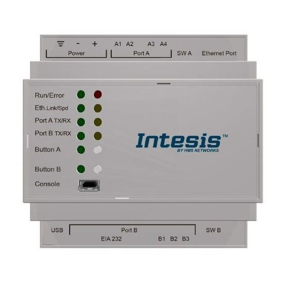
KNX – DALI Intesis User Manual r1.1 EN Powering the device A power supply working with any of the voltage range allowed is needed (check section 0). Once connected the RUN led (Figure above) will turn on. WARNING! In order to avoid earth loops that can damage the gateway and/or any other equipment connected to it, we strongly recommend: •... -
Page 21: Set-Up Process And Troubleshooting
KNX – DALI Intesis User Manual r1.1 EN 4 Set-up process and troubleshooting Pre-requisites It is necessary to have the KNX system (specific KNX power supply and bus) operative and properly connected to the corresponding port of the gateway. It is also required to have a DALI installation connected to the gateway, in its respective dali port. -
Page 22: Configuration Tab
KNX – DALI Intesis User Manual r1.1 EN 4.2.3 Configuration tab Select the Configuration tab to configure the connection parameters. Three subsets of information are shown in this window: General (Gateway general parameters), KNX (KNX interface configuration) and DALI (DALI channel and DALI devices configuration). -
Page 23: Sending The Configuration To Intesis
KNX – DALI Intesis User Manual r1.1 EN 4.2.5 Sending the configuration to Intesis When the configuration is finished, follow the steps to program the gateway. 1.- Click on Save button to save the project to the project folder on your hard disk (more information in Intesis MAPS User Manual). - Page 24 KNX – DALI Intesis User Manual r1.1 EN Figure 4.5 Diagnostic More information about the Diagnostic section can be found in Intesis MAPS user manual for Intesis KNX Series. © HMS Industrial Networks S.L.U - All rights reserved https://www.intesis.com This information is subject to change without notice 24 / 34...
-
Page 25: Set-Up Procedure
KNX – DALI Intesis User Manual r1.1 EN Set-up procedure 1. Install Intesis MAPS on your laptop, use the setup program supplied for this and follow the instructions given by the Installation wizard. 2. Install Intesis in the desired installation site. Installation can be on DIN rail or on a stable not vibrating surface (DIN rail mounted inside a metallic industrial cabinet connected to ground is recommended). -
Page 26: Electrical & Mechanical Features
KNX – DALI Intesis User Manual r1.1 EN 5 Electrical & Mechanical Features Plastic, type PC (UL 94 V-0) Size: Coin 20mm x 3.2mm Net dimensions (d h): 90x88x56 mm Enclosure Battery Capacity: 3V / 225mAh Recommended space for installation (d h): 130x100x100mm Type: Manganese Dioxide Lithium Color: Light Grey. -
Page 27: Dimensions
KNX – DALI Intesis User Manual r1.1 EN 6 Dimensions 56 mm (h) 88 mm (w) 90 mm (d) Recommended available space for its installation into a cabinet (wall or DIN rail mounting), with space enough for external connections 100 mm (h) 100 mm (w) 130 mm (d) ©... -
Page 28: Annex A - Quick Setup And Commissioning Of A Dali Network
KNX – DALI Intesis User Manual r1.1 EN Annex A – Quick setup and commissioning of a DALI network This section provides a brief summary on commissioning a DALI channel using MAPS software tool. The process of commissioning involves: Scanning the existing ballasts (ECGs) in the DALI network Identifying their physical location Obtaining or setting up ECG short addresses Obtaining or editing ECG configuration parameters (preset levels, scenes, groups addressing…) -
Page 29: Ecg Declaration In Project
KNX – DALI Intesis User Manual r1.1 EN ECG declaration in project Once new project has been created, ballasts can be added to the configured project, without the need of scanning them in bus. As mentioned above, this allows defining its configuration parameters (preset values, groups, scenes, …) before having actual access to the installation. -
Page 30: Scan And Commissioning Of Ecgs
KNX – DALI Intesis User Manual r1.1 EN Figure Instantiation of DALI ECGs If too many ECGs have been instantiated, they can be deleted by selecting them, and pressing button ‘Delete ECG(s)’. Multiple selection is also possible. Figure Deleting DALI ECGs Finally, for all ballasts in configuration, you will need to define: ECG Name (optional): Name to ease its identification in the network Device type: It’s important that this field is suitably chosen and according to existing ballast in the... - Page 31 KNX – DALI Intesis User Manual r1.1 EN Finally, click on button ‘Connect’ in order to establish connection. Bar at the bottom in MAPS main window will become green, switching from ‘Not Connected’ to ‘Connected’. Now go back to ‘Configuration’ tab of MAPS, and click on button ‘Commissioning’: Figure DALI commissioning button Commissioning window will appear:...
- Page 32 KNX – DALI Intesis User Manual r1.1 EN There is also a ‘DALI network’ area that will show DALI scan results, empty by now. In order to start a DALI network scan, select suitable DALI channel (if applicable) and then click on button ‘Scan’: Figure Starting DALI scan process New ballasts will appear in the ‘DALI Network’...
- Page 33 KNX – DALI Intesis User Manual r1.1 EN 1. Identify the ballast in the installation with the Wink button (it will set it to MAX level for a while), and then double click in short address field of the ballast in DALI Network window, and assign it an address 0..63. 2.
- Page 34 KNX – DALI Intesis User Manual r1.1 EN In Figure’s example, we’ll associate LED ballasts with short addres 0, 1 and 2 and Emergency light with short address 5 to existing ballasts (with ‘<-‘ button), and add ballasts from short addresses 3 and 4 as new ballasts in the configuration.
Need help?
Do you have a question about the Intesis DALI and is the answer not in the manual?
Questions and answers