Advertisement
Quick Links
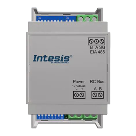
Interfaz IN485HIT001R000
Instrucciones de seguridad
ATENCIÓN
Siga atentamente estas instrucciones de seguridad e
instalación. Un manejo inadecuado puede ocasionar daños
graves para su salud y daños irreparables en la interfaz y/o
en la unidad interna del aire acondicionado.
•
Esta interfaz debe ser instalada por personal técnico
acreditado (electricista, instalador o personal técnico
cualificado) y siguiendo todas las instrucciones de
seguridad.
•
Antes
de
manipular
acondicionado, asegúrese de que está completamente
desconectado de la red eléctrica.
•
En caso de instalación mural del interfaz junto a la
unidad interior del aire acondicionado, fije la interfaz
de forma segura siguiendo las instrucciones del
diagrama de abajo.
•
La interfaz debe ser instalada en una ubicación con
acceso restringido.
Instrucciones de instalación
•
Desconecte el sistema AC de la red eléctrica.
•
Fije el interfaz a la pared junto a la unidad interior del
aire acondicionado siguiendo las instrucciones del
diagrama de abajo (respete las instrucciones de
seguridad anteriores).
•
Conecte la interfaz al bus AB en cualquier punto de
este. El bus AB es el bus que conecta la unidad interior
de aire acondicionado y el mando por cable. Es un bus
de dos cables que conecta los terminales AB de ambos.
Este bus no tiene polaridad.
•
Conecte el bus EIA-485 al conector EIA485 de la
interfaz (para conexión MS/TP).
•
Tape la unidad interior del aire acondicionado y vuelva
a conectarlo a la red eléctrica.
•
Siga las instrucciones del manual de usuario para la
configuración y puesta en servicio de la interfaz.
•
Siga las instrucciones de la página siguiente para
configurar
la
interfaz
Interruptores.
IMPORTANT! Connection to an external power supply: This gateway is powered by the AB bus itself, and there is no need to
connect an external power supply. Nonetheless, the bus could not supply the needed power* depending on the number and type of
remote controllers installed. If that's the case, connect a 12VDC/AC SELV-rated NEC class 2 or Limited Power Source (LPS) power
supply in the gateway's Power connector.
*Some signs indicating there is not enough power in the bus may include, for example, a malfunction
of the remote controllers' displays or performance.
BACnet MS/TP
EIA-485 Bus
Conexión de la malla
Shield connection
Conecte la malla a tierra
solo en un punto
Connect shield to ground
only at one point
FCC:
This device complies with part 15 of the FCC Rules. Operation is subject to the following two conditions:
1) This device may not cause harmful interference.
2) This device must accept any interference received, including interference that may cause undesired operation.
IMPORTANTE:
Mantenga el cable de conexión lo más
alejado posible del cableado eléctrico y del cable de tierra,
no los enrolle juntos.
Version 1.0
© HMS Industrial Networks S.L.U - All rights reserved
This information is subject to change without notice
en
el
interior
del
aire
a
través
de
los
Micro
AB Bus
Interface IN485HIT001R000
Safety instructions
WARNING
Follow carefully this safety and installation instructions.
Improper work may lead to serious harmful for your health
and also may damage seriously the interface and/or the AC
indoor unit.
•
This interface must be installed by accredited technical
personnel
(electrician,
personnel) and following all the safety instructions.
•
Before manipulating the AC indoor unit be sure it is
completely disconnected from mains power.
•
In case of wall mounting of the interface beside the AC
indoor unit, fix the interface safely following the
instructions of the diagram below.
•
This interface must be installed in an access-restricted
location.
Installation instructions
•
Disconnect the AC system from mains power.
•
Fix the interface beside the AC indoor unit (wall
mounting) following the instructions in the diagram
below (respect the safety instructions given above).
•
Connect the interface at any point of the AB bus. The
AB bus is the bus that connects the AC indoor unit and
the wired remote controller. It is a two-wire bus
connecting AB terminals of both. This AB connection
has no specific polarity.
•
Connect the EIA-485 bus to the connector EIA485 of
the interface (for MS/TP connection).
•
Close the AC indoor unit and reconnect it to mains
power.
•
Follow the instructions on the user manual for
configuring and commissioning the interface.
•
Follow the instructions on the next page to configure
the interface through its on-board DIP switches.
OPCIONAL/OPTIONAL
IMPORTANT:
Keep the cable as far as possible from
mains and ground wires. Do not bundle them together.
installer,
or
technical
Conector/
Connector
A/B
URL
https://www.intesis.com
1 / 2
Advertisement

Related Manuals for HMS Networks Intesis IN485HIT001R000


Summary of Contents for HMS Networks Intesis IN485HIT001R000
- Page 1 Interfaz IN485HIT001R000 Interface IN485HIT001R000 Instrucciones de seguridad Safety instructions WARNING ATENCIÓN Follow carefully this safety and installation instructions. Siga atentamente estas instrucciones de seguridad e Improper work may lead to serious harmful for your health instalación. Un manejo inadecuado puede ocasionar daños and also may damage seriously the interface and/or the AC graves para su salud y daños irreparables en la interfaz y/o indoor unit.
- Page 2 Interfaz IN485HIT001R000 Interface IN485HIT001R000 Configuración por Micro Interruptores Configuration through DIP switches SW1 Configuración del dispositivo y velocidad de baudios BACnet MS/TP – Device configuration and BACnet MS/TP baudrate Valor binario Valor binario Interruptores Descripción Interruptores Descripción Binary value Binary value Switches Description Switches...
Need help?
Do you have a question about the Intesis IN485HIT001R000 and is the answer not in the manual?
Questions and answers