
Related Manuals for Pentair SOLARTOUCH 521592


Summary of Contents for Pentair SOLARTOUCH 521592
- Page 1 SOLARTOUCH SOLAR CONTROLLER ® FOR POOL AND SPA INSTALLATION USER’S GUIDE IMPORTANT SAFETY INSTRUCTIONS READ AND FOLLOW ALL INSTRUCTIONS SAVE THESE INSTRUCTIONS SolarTouch Solar Control System Installation and User’s Guide ®...
-
Page 2: Table Of Contents
Contents Important Warning and Safety Instructions..........i-ii Introduction....................SolarTouch Controller Control Panel ..............Using the SolarTouch Controller Control Buttons ..........SolarTouch Controller Main Status Screens ............. Temperature Control..................Normal Operating Mode..................SolarTouch Controller Menus (Main Menu - Advanced Menu) ......Heating ...................... -
Page 3: Important Warning And Safety Instructions
IMPORTANT WARNING AND SAFETY INSTRUCTIONS Most states and local codes regulate the construction, installation, and operation of public pools and spas, and the construction of residential pools and spas. It is important to comply with these codes, many of which directly regulate the installation and use of this product. - Page 4 IMPORTANT WARNING AND SAFETY INSTRUCTIONS To reduce the risk of injury, do not permit children to use this product. A wire connector is provided on this unit to connect a minimum 8 AWG (8.4 mm) solid copper conductor between this unit and any metal equipment, metal enclosures of electrical equipment, metal water pipe, or conduit within 5 feet (1.5 m) of the unit.
-
Page 5: Introduction
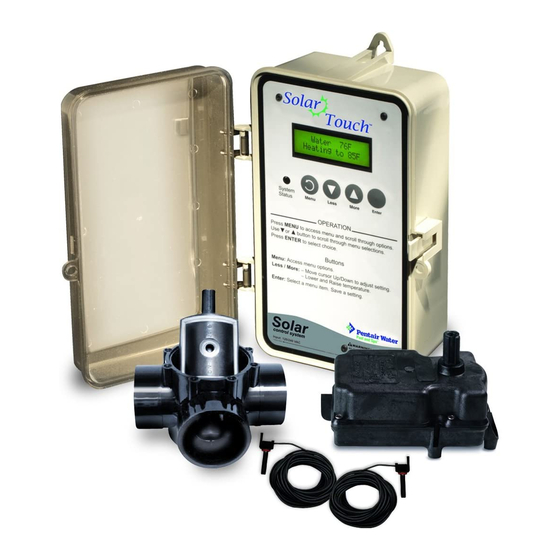
Introduction The SolarTouch Solar Controller system consists of a four button controller, a valve ® actuator, a positive sealed diverter valve and two temperature sensors (used for water and solar). SolarTouch solar controller maximizes available solar heat by monitoring the temperature of both the solar collectors and the pool water. When the pool calls for heat, and solar is available (collectors are in energy-receiving mode), the controller automatically diverts the water flowing between the pool’s filter and gas heater or heat pump and circulates the water through the solar collectors. -
Page 6: Solartouch Controller Control Panel
SolarTouch Controller Control Panel ® Liquid Crystal Display (LCD): The system LCD displays backlighting for easy viewing of the menu items and status messages. Each button press will light the display. When an event message is displayed, the backlight will also be on. System Status LED indicator: When indicator is green, the system is running normally. -
Page 7: Using The Solartouch Controller Control Buttons
Using the SolarTouch Controller Control Buttons ® Main Menu Water 60F Water 60F Target Temp 81F Solar 50F Press Enter button Press Menu button Main Menu Enable/Disable Enable Enter Enter Heating Menu / Disable Enter Press Target Temp UP/DOWN Enter Enter button 104F... -
Page 8: Temperature Control
Temperature Control From the SolarTouch Controller control panel you can set the desired target temperature ® setting using the Less (Down arrow) button or More (Up arrow) button. After the target temperature is reached, the solar system will automatically switch off or when solar energy is no longer available. -
Page 9: Solartouch Controller Menus (Main Menu - Advanced Menu)
SolarTouch Controller Menus ® Main Menus Use the Main Menu for everyday solar operating features and the Advanced Menu for solar utility settings. To access the Main Menu, press the MENU button. The Main Menu items are as follows: Main Menu Heating Menu Enable/Disable: [Enable/Disable] Target Temp - 40°... - Page 10 Heating (continued) Heating will start when the Start differential condition is met and the water temperature is below the Target Temp. When these conditions are satisfied heating is turned ON. Example: Water Temperature is 75° F; Target Temperature is 82° F. When the roof solar collectors temperature exceeds the water temperature by 6°...
-
Page 11: Cooling
Cooling The SolarTouch Controller can cool the pool/spa by circulating water through the solar ® collectors when the solar temperature is at a lower temperature than the pool/spa water (typically at night). Cooling must be enabled in the Cooling Menu. The default setting is “Disabled.”... -
Page 12: Freeze Protect
Freeze Protect When the solar sensor temperature falls to 40°F (4°C) or below, the pool/spa water is automatically circulated through the system to prevent freezing. If the solar sensor is placed at the solar collectors and when the temperature in the solar collector reaches 42°... -
Page 13: Manual Mode
Manual Mode To access the Manual mode menu from the Advanced menu, press and hold the MENU button for three (3) seconds. Manual mode is useful for system setup or service purposes. Manual mode settings will override existing SolarTouch Controller settings. After you ®... -
Page 14: Calibrating Sensors
Calibrating Sensors Control Panel LED indicator To adjust the calibration of the pool water and solar collector sensor go to: Advanced Menu > Utility Menu >Calibrate Water or Calibrate Solar Sensor Use the Up or Down arrow button to adjust the calibration of the sensor. The sensor can be adjusted up to +/-10°. -
Page 15: Error Conditions
Error Conditions Error Conditions When the control panel LED indicator is solid red, a sensor error has occurred; a blinking LED indicates an IntelliFlo Pump communication problem or the IntelliFlo Pump has ® ® been manually stopped. For sensor resistance data, see page 22. If the water or solar temperature sensor is shorted or open, heating and cooling will stop and not restart until the condition is corrected. - Page 16 Using IntelliFlo and IntelliPro Variable Speed Pump ® ® ® The SolarTouch Controller communicates with the IntelliFlo or IntelliPro Variable Speed Pump via a two conductor RS-485 communication cable (P/N 350122) which is connected to the COM PORT on the SolarTouch controller circuit board (see wiring diagram on page 19).
- Page 17 Setting Pump Speeds (IntelliFlo and IntelliPro VS Pumps) ® ® Setting the IntelliFlo/IntelliPro Variable Speed (VS) Pump speed for solar/cooling and freeze protect mode is setup in the pump’s “Ext. Ctrl” menu. Note: The IntelliFlo pump must be in “Running Schedule” mode to communicate with the SolarTouch Controller.
-
Page 18: Mounting The Suntouch Controller
Mounting the SunTouch Controller ® The SolarTouch Controller can be mounted on a flat vertical surface, such as a wall or post. Note: Select a convenient location to mount the SolarTouch controller and be sure the location is greater than five (5) feet from the pool or spa and no further than 15 feet from the pool/spa valve. -
Page 19: Installing Conduit And Wire To The Enclosure
Installing Conduit and Wire to the Enclosure • Use No. 14 minimum to No. 6 maximum AWG for power relay circuits depending on the power requirement. Be sure to follow all regulation safety codes for the number and size of conductors that can be installed in various sizes of conduit. -
Page 20: Grounding And Bonding To The Controller
Grounding and Bonding to the SolarTouch Controller ® Connect a ground wire from the primary electrical panel to the SolarTouch Controller ground bus bar. Also ground each piece of high voltage (120 VAC or 240 VAC) equipment that is connected to the Controller relays. The SolarTouch controller must also be connected to the pool bonding system using an 8 AWG (minimum) wire. -
Page 21: Transformer Ac Power Connections (High Voltage Connections)
Transformer AC Power Connections High Voltage Wiring The high voltage wiring section is located inside the SolarTouch Controller enclosure on ® the right side. The SolarTouch controller can be connected either to 120 VAC or 220 VAC. The SolarTouch controller should be wired to receive continuous power (connect directly to sub-panel). -
Page 22: Solartouch Controller Circuit Board Connections
Controller Circuit Board Connections The SolarTouch Controller circuit board is mounted onto the back of the enclosure. ® The circuit provides the voltage connections to switch the solar booster pump, cleaner pump, solar valve actuators, connections for temperature sensors and connections for communication with an IntelliFlo or IntelliPro Pump via RS-485 communication cable. -
Page 23: Solartouch Controller Auxiliary Outputs
SolarTouch Controller Auxiliary Outputs (Pool Filter Pump, ® Booster Pump, Cleaner and Time Clock) See Cleaner and Solar Pump Wiring Diagrams on page 20 High voltage relay output, as a solar booster pump control The SolarTouch Controller control panel can control a high voltage booster pump for solar in addition to the valve actuator. -
Page 24: Solar System Installation
Time clock pool daily filtering override When using a single speed pump, or an IntelliFlo or IntelliPro VS 3050 / 4x160 ® ® Pump, for daily pool filtering schedules SolarTouch Controller requires the pump to be ® connected to an external 24 hour time clock. In order to override the daily pool filtering schedules, a two-pole timer or two-pole relay for switching the pump on or off is required. -
Page 25: Winterizing Solar Collectors
Solar System Installation • To ensure maximum flow of water through the solar panels, a solar booster pump may be required if panels are installed at a very high elevation. Please review your filter pump specifications. • It is recommended that the solar panels are mounted in a way that gravity will allow draining whenever the filter pump or solar is not on. -
Page 26: Installing And Connecting Temperature Sensors
Installing and Connecting Temperature Sensors Water Temperature Sensor (P/N 520272) To install the water sensor: Select a convenient location to mount the water sensor in the plumbing system between the filter pump and filter. Drill a 3/8” diameter hole in one side of the pipe. -
Page 27: Solar Hydraulics System
Solar Hydraulics System Plumb the solar system in accordance with recommended hydraulics shown below. • 2” diameter plumbing is advised to ensure maximum flow of water through the solar panels. A solar booster pump should be added if panels are installed at a very high elevation. -
Page 28: Temperature Vs. Resistance Data
Temperature vs. Resistance Data Solar systems use 10K Ohm thermistor sensors. When the solar sensor is disconnected from the SolarTouch Controller system, the sensor will read 10K Ohm at 77° F (25° C). ® Refer to the following table for the resistance at other temperatures. An accurate reading should give a temperature setting that is accurate to ±0.2°... -
Page 29: Solartouch Controller Power Specifications
SolarTouch Controller Power Specifications ® Power: 120 VAC, 0.4A 50/60 Hz 240 VAC, 0.2A 50/60 Hz Output: 24 VAC (for solar actuator valve) High Voltage isolated contacts 10 A at 120 VAC/ 240 VAC SolarTouch Controller Package Contents (Three Versions) SolarTouch Controller kit with 3-way positive seal solar valve with drain-down (P/N 521592) •... - Page 30 Notes Notes SolarTouch Solar Control System Installation and User’s Guide ®...
- Page 31 Notes SolarTouch Solar Control System Installation and User’s Guide ®...
- Page 32 Pentair Water Pool and Spa, Inc. Those names and brands may be the trademarks or registered trademarks of those third parties.
Need help?
Do you have a question about the SOLARTOUCH 521592 and is the answer not in the manual?
Questions and answers