Table of Contents
Advertisement
Quick Links
®
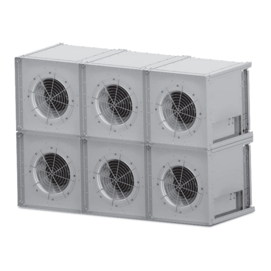
This publication contains the installation, operation and
maintenance procedures for standard units of the MPA:
Modular Plenum Array.
Carefully read this publication and any
supplemental documents prior to any
Installation or maintenance procedure.
Protect yourself and others by observing all safety
information. Failure to comply with instructions could result
in personal injury and/or property damage. For information
and instructions on special equipment, contact Loren Cook
Company at (417) 869-6474.
General Safety
Only qualified personnel should install the fan. Personnel
should have a clear understanding of these instructions and
should be aware of general safety precautions. Improper
installation can result in electric shock, possible injury due
to coming in contact with moving parts, as well as other
potential hazards.
Important Guidelines:
• Follow all local electrical and safety codes, as well as
the National Electrical Code (NEC) and the National Fire
Protection Agency (NFPA), where applicable. In Canada,
follow the Canadian Electric Code (CEC).
• The rotation of the impeller is critical. It must be free to rotate
without striking or rubbing any stationary objects.
• Motor must be securely mounted and adequately grounded.
• Do not operate fan impeller faster than max catalogued fan
rpm. Adjustments to fan speed significantly effects motor
load. If the fan speed is changed, the motor current should be
checked to be sure it is not exceeding the motor nameplate
amps.
• Do not allow the power cable to kink or come in contact with
oil, grease, hot surfaces, or chemicals. Replace power cable
immediately if damaged.
• Verify that the power source is compatible with the equipment.
MPA IO&M
Installation, Operation, and Maintenance Manual
Rotating Parts & Electrical Shock Hazard:
Fans should be installed and serviced by qualified personnel only.
Disconnect electric power before working on unit (prior to removal of
guards or entry into access doors).
Follow proper lockout / tagout procedures to ensure the unit cannot be
energized while being installed or serviced.
A disconnect switch should be placed near the fan in order that the
power can be swiftly cut off, in case of an emergency and in order that
maintenance personnel are provided complete control of the power
source.
When servicing the fan, the motor may be hot enough to cause pain or
injury. Allow motor to cool before servicing
Grounding is required. All field-installed wiring must be completed by
qualified personnel. All field installed wiring must comply with National
Electric Code (NFPA 70) and all applicable local codes.
Fans and blowers create pressure at the discharge and vacuum at the
inlet. This may cause objects to get pulled into the unit and objects to
be propelled rapidly from the discharge. The discharge should always
be directed in a safe direction and inlets should not be left unguarded.
Any object pulled into the inlet will become a projectile capable of
causing serious injury or death.
When air is allowed to move through a non-powered fan, the impeller
can rotate, which is referred to as windmilling.Windmilling will cause
hazardous conditions due to unexpected rotation of components.
Impellers should be blocked in position or air passages blocked to
prevent draft when working on fans.
Friction and power loss inside rotating components will cause them
to be a potential burn hazard. All components should be approached
with caution and/or allowed to cool before contacting them for
maintenance.
Under certain lighting conditions, rotating components may appear
stationary. Components should be verified to be stationary in a
safe manner, before they come into contact with personnel, tools or
clothing.
Failure to follow these instructions could result in death or serious
injury.
Receiving and Inspection
Carefully inspect the fan and accessories for any damage
and shortage immediately upon receipt of fan. All Cook
products are carefully constructed and inspected before
shipment to insure the highest quality and performance.
• Turn the wheel by hand to ensure it turns freely and does
not bind.
• Compare all components with the bill of lading or packing
list to verify that the proper unit was received.
• Check each unit for any damage that may have occurred
in transit.
• Record on the Delivery Receipt any visible sign of
damage.
MPA
Modular Plenum Array
B51223-005
Advertisement
Table of Contents

Related Manuals for COOK MPA Series


Summary of Contents for COOK MPA Series
- Page 1 Carefully inspect the fan and accessories for any damage • The rotation of the impeller is critical. It must be free to rotate and shortage immediately upon receipt of fan. All Cook without striking or rubbing any stationary objects. products are carefully constructed and inspected before •...
- Page 2 Fans are designed to be lifted and moved as a single Long Term Storage module. Cook does not recommend lifting connected fan If a fan is to be stored for any length of time and the modules unless the fan module(s) is supported on a common bearings are re-greasable, the motor bearings should base.
- Page 3 Motor Maintenance Verify fastener tightness, these may have loosened during shipment or installation: The three basic rules of motor maintenance are to keep the • Bushing set screw torque motor clean, dry, and properly lubricated. Keeping motors • Bolts on inlet funnel. and windings clean is important because dirt and dust •...
- Page 4 If a final trim balance is required, it is the end user’s responsibility to bring the fan back to factory specifications (0.15 in/ sec Max). Final trim balancing is not the responsibility of Cook. Foundation Critical to every fan installation is a strong, level foundation.
- Page 5 Radial Gap, Overlap, and Impeller *Intake Side Shown Alignment • 1/2-13 x 1.00 Grade 5 Hex Head Cap Screw (or equivalent) 4 required (1 in each corner) Efficient fan performance can be maintained by having • 1/2 Flat Washer, 8 required (2 in each corner) the correct gap and overlap between the impeller and inlet •...
- Page 6 Piezometric Data Front Pressure Tap Piezometer HIGH PRESSURE LOW PRESSURE How It Works The Piezo system is based on the principle of a flow nozzle. The inlet funnel of the fan is used as the flow nozzle, and the flow can be calculated by measuring the static pressure drop through the inlet funnel.
- Page 7 Parts List Part Description Wheel Inlet Motor MPA IO&M B51223-005...
- Page 8 Limited Warranty Loren Cook Company warrants that your Loren Cook fan was manufactured free of defects in materials and workmanship, to the extent stated herein. For a period of one (1) year after date of shipment, we will replace any parts found to be defective without charge, except for shipping costs which will be paid by you.
Need help?
Do you have a question about the MPA Series and is the answer not in the manual?
Questions and answers