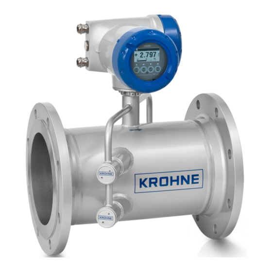
KROHNE OPTISONIC 7300 Quick Start Manual
Ultrasonic process gas flowmeter
Hide thumbs
Also See for OPTISONIC 7300:
- Supplementary instructions manual (36 pages) ,
- Supplementary instructions manual (36 pages) ,
- Supplementary instructions manual (44 pages)

Related Manuals for KROHNE OPTISONIC 7300


Summary of Contents for KROHNE OPTISONIC 7300
- Page 1 OPTISONIC 7300 OPTISONIC 7300 OPTISONIC 7300 OPTISONIC 7300 Quick Start Quick Start Quick Start Quick Start Ultrasonic process gas flowmeter ER 1.1.7_ © KROHNE 09/2018 - 4002312802 - QS OPTISONIC 7300 R04 en...
-
Page 2: Table Of Contents
4 Technical data 4.1 Dimensions and weight ....................25 4.1.1 Flow sensor in carbon steel....................26 4.1.2 Signal converter housing ...................... 30 4.1.3 Mounting plate of field housing .................... 31 www.krohne.com 09/2018 - 4002312802 - QS OPTISONIC 7300 R04 en... -
Page 3: Safety Instructions
If you need to return the device to the manufacturer or supplier, please fill out the form • contained on the CD-ROM and send it with the device. Unfortunately, the manufacturer cannot repair or inspect the device without the completed form. 09/2018 - 4002312802 - QS OPTISONIC 7300 R04 en www.krohne.com... -
Page 4: Installation
5 Signal cable (remote versions only) INFORMATION! Assembly materials and tools are not part of the delivery. Use the assembly materials and tools in compliance with the applicable occupational health and safety directives. www.krohne.com 09/2018 - 4002312802 - QS OPTISONIC 7300 R04 en... -
Page 5: Device Description
Product specific information and extensive product specification is available using PICK, the Product Information Center KROHNE web-tool. PICK can be found via the service menu button on the KROHNE.com website. The following versions are available: • Compact version (the signal converter is mounted directly on the flow sensor) •... -
Page 6: Nameplates
4 PED data 5 Calibration data 6 Type designation and manufacturer date of the flowmeter / CE sign with number(s) of notified body / bodies 7 Name and address of the manufacturer www.krohne.com 09/2018 - 4002312802 - QS OPTISONIC 7300 R04 en... -
Page 7: Examples Of Nameplates On The Signal Converter (Field Housing)
6 Info / web address and Rohs logo 7 Type designation and manufacturer date of the flowmeter / CE sign with number(s) of notified body / bodies 8 Name and address of the manufacturer 09/2018 - 4002312802 - QS OPTISONIC 7300 R04 en www.krohne.com... - Page 8 Do not use the terminals A+ and A- at the same time. The system will be damaged by the direct voltage of 24 VDC and a 1 A peak current. www.krohne.com 09/2018 - 4002312802 - QS OPTISONIC 7300 R04 en...
-
Page 9: Storage
• Allen key (4 and 5 mm) • Small screwdriver • Wrench for cable glands and for pipe mounting bracket (remote version only); refer to Mounting the field housing, remote version on page 15 09/2018 - 4002312802 - QS OPTISONIC 7300 R04 en www.krohne.com... -
Page 10: General Requirements
2.8 Installation requirements for the flow sensor To secure the optimum functioning of the flowmeter, please note the following observations. The OPTISONIC 7300 is designed for the measurement dry gas flow. Excess of liquids may disturb the acoustic signals and should thus be avoided. -
Page 11: Installation Conditions
Figure 2-9: Recommended inlet and oulet for DN100 / 4" 10 DN 3 DN 2.9.2 T-section Figure 2-10: Distance behind a T-section 1 2 path 10 DN, 1 path 20 DN 09/2018 - 4002312802 - QS OPTISONIC 7300 R04 en www.krohne.com... -
Page 12: Control Valve
Figure 2-11: Not recommended installation of the flowmeter and valve in the same pipeline 2.9.4 Flange deviation CAUTION! Max. permissible deviation of pipe flange faces: 0.5 mm / 0.02" Figure 2-12: Flange deviation www.krohne.com 09/2018 - 4002312802 - QS OPTISONIC 7300 R04 en... -
Page 13: Installation Position
< -15 < -15° < -15 < -15 Figure 2-13: Installation position • Horizontal or vertical: allowed installation position in case of dry gas. Figure 2-14: Horizontal and vertical installation 09/2018 - 4002312802 - QS OPTISONIC 7300 R04 en www.krohne.com... -
Page 14: Thermal Insulation
For devices in hazardous area, additional maximum temperature and insulation precautions apply. Please refer to the Ex documentation. Figure 2-15: Leave vent holes free 1 Transducers 2 Connection box 3 Vent holes www.krohne.com 09/2018 - 4002312802 - QS OPTISONIC 7300 R04 en... -
Page 15: Mounting The Field Housing, Remote Version
Figure 2-16: Pipe mounting of the field housing 1 Fix the signal converter to the pipe. 2 Fasten the signal converter using standard U-bolts and washers. 3 Tighten the nuts. 09/2018 - 4002312802 - QS OPTISONIC 7300 R04 en www.krohne.com... -
Page 16: Turning The Display Of The Field Housing Version
Each time a housing cover is opened, the thread should be cleaned and greased. Use only resin- free and acid-free grease. Ensure that the housing gasket is properly fitted, clean and undamaged. www.krohne.com 09/2018 - 4002312802 - QS OPTISONIC 7300 R04 en... -
Page 17: Electrical Connections
1 Signal converter 2 Open connection box 3 Tool for releasing connectors 4 Marking on cable 5 Insert cable (1 path flowmeter) or cables (2 path flowmeter) through cable glands 09/2018 - 4002312802 - QS OPTISONIC 7300 R04 en www.krohne.com... - Page 18 2 Cable glands 3 Grounding clamps 4 Cable with metal shielding bush Figure 3-3: Connect the cables on the signal converter INFORMATION! Connect the cable on connector with similar numeral marking www.krohne.com 09/2018 - 4002312802 - QS OPTISONIC 7300 R04 en...
-
Page 19: Power Supply Connection
3 24 VAC/DC (AC: -15% / +10%; DC: -25% / +30%), 22 VA or 12 W DANGER! The device must be grounded in accordance with regulations in order to protect personnel against electric shocks. 09/2018 - 4002312802 - QS OPTISONIC 7300 R04 en www.krohne.com... -
Page 20: Laying Electrical Cables Correctly
2 Tighten the screw connection of the cable entry securely. 3 Never mount the housing with the cable entries facing upwards. 4 Seal cable entries that are not needed with a plug. www.krohne.com 09/2018 - 4002312802 - QS OPTISONIC 7300 R04 en... -
Page 21: Inputs And Outputs, Overview
• For hazardous areas, all of the input/output variants for the housing designs with terminal compartment in the Ex d (pressure-resistant casing) or Ex e (increased safety) versions can be delivered. • For connection and operation of Ex devices, note the supplementary instructions. 09/2018 - 4002312802 - QS OPTISONIC 7300 R04 en www.krohne.com... -
Page 22: Description Of The Cg Number
Two active current inputs (for Ex i I/O) No additional module installed No further module possible Table 3-1: Description of abbreviations and CG identifier for possible optional modules on terminals A and B www.krohne.com 09/2018 - 4002312802 - QS OPTISONIC 7300 R04 en... -
Page 23: Fixed, Non-Alterable Input/Output Versions
NAMUR ® NAMUR + HART active passive 3 4 0 passive NAMUR ® NAMUR + HART passive passive 2 5 0 active active 1 Function changed by reconnecting 2 Changeable 09/2018 - 4002312802 - QS OPTISONIC 7300 R04 en www.krohne.com... -
Page 24: Alterable Input/Output Versions
V/D- (1) Modbus (option) G _ _ max. 2 optional modules for term. A + B Common Sign. B Sign. A (D1) (D0) 1 Changeable 2 Not activated bus terminator www.krohne.com 09/2018 - 4002312802 - QS OPTISONIC 7300 R04 en... -
Page 25: Technical Data
= 155 mm / 6.1" b = 230 mm / 9.1" c = 260 mm / 10.2" Total height = H + a 1 The value may vary depending on the used cable glands. 09/2018 - 4002312802 - QS OPTISONIC 7300 R04 en www.krohne.com... -
Page 26: Flow Sensor In Carbon Steel
PN [bar] PN 16 PN 16 PN 16 Table 4-2: Dimensions and weight in mm and kg 1 Di = inner diameter at flange face. Inner tube diameter may be smaller. www.krohne.com 09/2018 - 4002312802 - QS OPTISONIC 7300 R04 en... - Page 27 31.5 32.0 23.3 Table 4-4: Dimensions and weight in inch / mm and lb / kg 1 Di = inner diameter at flange face. Inner tube diameter may be smaller. 09/2018 - 4002312802 - QS OPTISONIC 7300 R04 en www.krohne.com...
- Page 28 21.6 2438 1106 Table 4-6: Dimensions and weight in inch / mm and lb / kg 1 Di = inner diameter at flange face. Inner tube diameter may be smaller. www.krohne.com 09/2018 - 4002312802 - QS OPTISONIC 7300 R04 en...
- Page 29 25.2 11.8 1382 Table 4-7: Dimensions and weight in inch / mm and lb / kg 1 Di = inner diameter at flange face. Inner tube diameter may be smaller. 09/2018 - 4002312802 - QS OPTISONIC 7300 R04 en www.krohne.com...
-
Page 30: Signal Converter Housing
4.75 6.10 11.60 10.90 12.60 Table 4-9: Dimensions and weight in inch and lb INFORMATION! The weight of a field stainless steel converter housing is 14 kg / 30.9 lb www.krohne.com 09/2018 - 4002312802 - QS OPTISONIC 7300 R04 en... -
Page 31: Mounting Plate Of Field Housing
TECHNICAL DATA OPTISONIC 7300 4.1.3 Mounting plate of field housing Figure 4-3: Dimensions for mounting plate of field housing [mm] [inch] Ø9 Ø0.4 Table 4-10: Dimensions in mm and inch 09/2018 - 4002312802 - QS OPTISONIC 7300 R04 en www.krohne.com... - Page 32 • Process Analysis • Services Head Office KROHNE Messtechnik GmbH Ludwig-Krohne-Str. 5 47058 Duisburg (Germany) Tel.: +49 203 301 0 Fax: +49 203 301 10389 info@krohne.com The current list of all KROHNE contacts and addresses can be found at: www.krohne.com...
Need help?
Do you have a question about the OPTISONIC 7300 and is the answer not in the manual?
Questions and answers