
Related Manuals for GeoCue True View 410


Summary of Contents for GeoCue True View 410
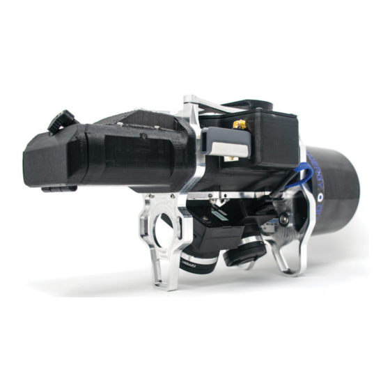
- Page 1 True View 410 Hardware User Guide GeoCue Group, Inc 8/3/2020 Version 1.3.1 8/3/2020...
-
Page 2: Table Of Contents
About GeoCue Group, Inc........................4 About True View® 410 ..........................5 A True View Cycle ........................... 5 True View 410 Hardware Integration Kit ....................6 Installing the Top Plate and Controller Box ..................6 Installing the Ronin Mount ........................ 10 True View 410 Installation ........................ - Page 3 True View 410 Hardware User Guide Y Offset ............................. 36 True View 410/M600 Pro – Mission Checklist ..................37 FAQ ..............................39 Support ..............................40 True View 410 Hardware User Guide 8/3/2020...
-
Page 4: About Geocue Group, Inc
Today GeoCue is the largest supplier of kinematic LIDAR processing tools in North America and LP360 is the world’s most widely used tool for exploiting point cloud data. In 2014, GeoCue Group started a division focused on using small Unmanned Aerial Systems for high accuracy mapping. Leveraging our... -
Page 5: About True View® 410
Cameras, a Quanergy M8 Ultra laser scanner and Applanix Position and Orientation System (POS), the result is a true 3D imaging sensor (3DIS). With its wide 120° fused field of view, the True View 410 provides high efficiency 3D color mapping with vegetation penetration in a payload package of 2.2 kg. -
Page 6: True View 410 Hardware Integration Kit
TRUE VIEW 410 HARDWARE INTEGRATION KIT The True View 410 was designed to be used with the GeoCue True View Integration kit, which includes an antenna mounting plate and a DJI Ronin gimbal mount with vibration dampeners. If your True View 410 and M600 were purchased through GeoCue, the antenna mounting plate and Ronin mount were installed by a GeoCue technician. - Page 7 True View 410 Hardware User Guide c. Set Screw (4) (Figure 3) Figure 3 d. 50mm Spacer (4) (Figure 4) Figure 4 e. Hex Driver – 1.5mm & 2mm (Figure 5) Figure 5 2. On the drone, remove the 4 screws indicated below (Figure 6). These screws will be used to attach the mounting plate later, so save them for step 5.
- Page 8 True View 410 Hardware User Guide 3. Apply Loctite to the 4 Set Screws and install in the empty screw spaces from Step 2 using a 1.5mm hex driver (Figure 7). WARNING - Do not overtighten. If screws are too tight, they will press into the plastic plate below and could cause the plate to crack.
- Page 9 True View 410 Hardware User Guide Figure 10 6. Install the controller box on to the top plate with the LEDs facing out away from the center of the drone. The controller box is designed to fit into the antenna mounting plate without the need for additional hardware.
-
Page 10: Installing The Ronin Mount
True View 410 Hardware User Guide INSTALLING THE RONIN MOUNT 1. On the drone, remove the 3 screws on each leg of the stock mount (Figure 11). Keep the screws, they will be used again. Figure 11 2. On the Ronin Mount, loosen the screws that hold the legs to the rails enough so that they can be rotated (Figure 12). - Page 11 True View 410 Hardware User Guide Figure 13 4. Using the screws removed from the drone in Step 1, apply Loctite to each screw and install the mount with the red lever facing the back of the aircraft (Figure 14).
-
Page 12: True View 410 Installation
The True View 410 mounts using a standard DJI Ronin mount on the DJI M600. The instructions below describe how to install the True View 410 on the M600 when you are ready to use the system to collect data. - Page 13 True View 410 Hardware User Guide Figure 17 5. Tighten the red lever until the True View is tightly locked in place. 6. Loop the safety lanyard through the upper metal plate of the True View and around one of the bars of the payload mount and close the safety lanyard (Figure 18).
- Page 14 True View 410 Hardware User Guide Figure 19 8. Attach the CAT6 cable to the True View unit (Figure 20). Figure 20 9. Attach the GNSS antenna cable to the True View unit (Figure 20) and screw the antenna on to the antenna mount (Figure 21).
- Page 15 True View 410 Hardware User Guide Figure 21 True View 410 Hardware User Guide 8/3/2020...
-
Page 16: True View 410 Battery
True View 410 Hardware User Guide TRUE VIEW 410 BATTERY The True View 410 is powered by its own 3200 mAh removable lithium-ion battery. The True View power system was designed to be standalone and does not use power from the aircraft’s power system. -
Page 17: True View 410 Universal Mass Storage (Ums)
SYSTEM CONFIGURATION FILE (SCF) The System Configuration file (SCF), SystemConfiguration.json, must reside on the True View 410 Universal Mass Storage and is copied into the Cycle\System folder upon creation of each Cycle. The SCF contains information on the calibration parameters of all components for each True View system and is used by True View EVO to process True View data. -
Page 18: Ccfsection8 - Camera
True View 410 Hardware User Guide CCFSECTION8 – CAMERA Figure 24 - Core Configuration – Camera This section is applicable for CCU firmware v2.0.x and later. If the “CameraFileTransferWindDown” is true, the True View is configured to operate in Standard mode and the images will get transferred to the UMS drive during the wind-down sequence. -
Page 19: Ccfsection15 - Battery
True View 410 Hardware User Guide The FOVCenter is set to 90° by default to indicate the center of the laser field of view is pointing downward at nadir and should not be changed. The FocWidth controls the active radial scan zone of the laser scanner. Normally set at 120° to only record data from the laser scanner between +/- 30°... -
Page 20: Ccfsection17 - Storage Auto Delete
True View 410 Hardware User Guide system is ready to take off. It will automatically start recording data when the sensor travels more than the “ProximityDistance” (in meters X, Y and Z) from the home point. Figure 29 - Controller Box SYS LED If “ProximityMode”... - Page 21 True View 410 Hardware User Guide If "AutoDelete” is false, the user must manually delete data from the UMS or SD cards. If storage space is full, flight data will not be stored. True View 410 Hardware User Guide 8/3/2020...
-
Page 22: True View 410 Field Operations
TRUE VIEW 410 FIELD OPERATIONS 1. BASE STATION The True View 410 records GNSS signals during flight which will be corrected later in EVO. This type of system is known as a PPK system. Base station processing methods should be considered during the planning process because the user will need to determine how they plan to correct their flight data before collecting. -
Page 23: Pre-Flight
True View 410 Hardware User Guide 2. PRE-FLIGHT 1. Ready the drone for flight and insert the battery into the True View unit (Figure 31). Figure 31 – Insert True View Battery 2. Lift all antennas up and tighten the nut (Figure 32) on the True View antenna. - Page 24 True View 410 Hardware User Guide 5. Turn on the True View unit with the switch located in the battery compartment (Figure 33). Figure 33 – True View Power Switch 6. Close the battery compartment door and lock the latch.
-
Page 25: Controller Box Leds
True View 410 Hardware User Guide 3. CONTROLLER BOX LEDS 8. When the power switch is turned on, the system will go through its startup procedure and all lights (Figure 34) on the controller box will flash yellow. After a few seconds, each LED light will begin to show a sequence of colors indicating status. - Page 26 True View 410 Hardware User Guide Figure 35 shows all the lighting sequences and their meanings. Figure 36 shows how to interpret the symbols in the table. Figure 35 – Controller Box LEDs Figure 36 – Controller BOX LED Legend...
-
Page 27: Heading Alignment Maneuver
True View 410 Hardware User Guide 4. HEADING ALIGNMENT MANEUVER The heading alignment maneuver needs to be done after takeoff, before flying the mission, and after the mission prior to landing for each flight. This maneuver is critical for getting accurate heading corrections for the IMU and will impact the results of the data if not performed. -
Page 28: After Landing
True View 410 Hardware User Guide 5. AFTER LANDING 1. After landing the SYS LED should be flashing yellow, indicating the system is transferring data. Do not power off the system during this time or it will interrupt the data transfer. -
Page 29: True View Evo
True View Evo is a 64-bit Windows® desktop application used for processing and exploiting True View sensor data. It is GeoCue’s LP360 point cloud exploitation product with the addition of a collection of tools for True View sensor data workflows. Currently, True View Evo is available in two licensing levels: •... -
Page 30: Logging In To Apx15
View Wi-Fi network and connect to the APX-15. CONFIGURE TRUE VIEW WI-FI 1. Power on the True View 410 and wait for 30 seconds, or until “Trueview410” appears in your list of Wi-Fi networks. a. If cannot find the network, turn off the True View 410, connect the UMS to laptop and delete the file “TV_hostapd.conf”... -
Page 31: Log In To Apx-15
The instructions below explain how log in to the APX-15. Be sure the True View Wi-Fi has been previously configured before attempting to connect to the APX-15. 1. Power on the True View 410 and wait for 30 seconds. 2. Connect to Trueview410 Wi-Fi network. -
Page 32: Download T04 Files
True View 410 Hardware User Guide DOWNLOAD T04 FILES 1. After you Log in to APX-15, on the left side menu select Data Logging -> Data Files -> Internal 2. Select the applicable T04 file(s). T04 files are named YYMMDDHHMM.T04. -
Page 33: Measuring Gnss Lever Arm Offsets
M600 with the GeoCue integration kit, the offsets have been preset by a GeoCue technician and should not need to be modified. If you are not using the GeoCue integration kit, or are installing the True View on a different aircraft, you will need to measure the offsets, then log in and enter them into the APX-15 (Figure 41). -
Page 34: Z Offset
True View 410 Hardware User Guide Z OFFSET The Z offset is the distance from the APX-15 to the GNSS antenna phase center in the up/down direction. If the GNSS antenna is above the APX-15, the offset is negative. If the antenna is below the APX-15, the offset is positive. -
Page 35: Offset
True View 410 Hardware User Guide X OFFSET The X offset is the distance from the APX-15 to the GNSS antenna, in the direction of the heading of the aircraft. If the antenna is forward of the APX 15, the X offset is positive. If the antenna is behind the APX-15, the offset is negative. -
Page 36: Y Offset
True View 410 Hardware User Guide Y OFFSET The Y offset is the distance from the APX-15 to the GNSS antenna, perpendicular to the heading of the aircraft. If you are standing behind the aircraft looking in the direction of the heading, the offset will be negative if the antenna is left of the centerline of the APX-15. -
Page 37: True View 410/M600 Pro - Mission Checklist
True View 410 Hardware User Guide TRUE VIEW 410/M600 PRO – MISSION CHECKLIST Step Action Notes 1. Setup base station and turn ON. 2. Check mission plan on iPad; modify if necessary. 3. Complete a safety briefing and flight plan review with field crew. - Page 38 True View 410 Hardware User Guide 30. Ensure landing area is still clear; complete the landing via Return to Home or manually as preferred. 31. After landing, turn off M600. 32. Verify SYS light is flashing yellow (transferring data). 33. Monitor the True View SYS LED; flashing Yellow means data is being copied to USM;...
-
Page 39: Faq
The base station should be configured to record at 1Hz. • Question - What are the base station requirements for the True View 410? Answer - The minimum requirement base station must include: o Static observations recorded to some media... -
Page 40: Support
True View 410 Hardware User Guide SUPPORT Normal support business hours are Monday - Friday, 8 AM — 5 PM USA Central Time. GeoCue Support website contains general workflow information, in addition to specific issue and error messages that you may encounter. Click on the link and search for information contained in the knowledge base.
Need help?
Do you have a question about the True View 410 and is the answer not in the manual?
Questions and answers