Table of Contents
Advertisement
Quick Links
Installation Instructions
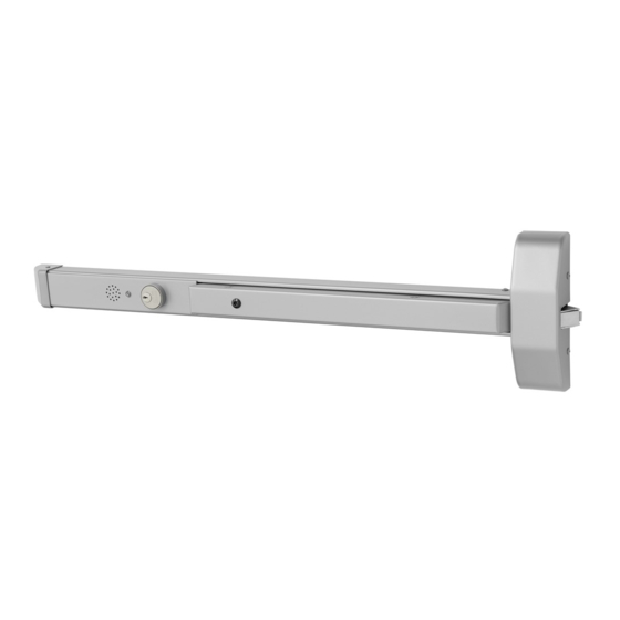
5300 Series
Alarmed Exit Devices
WARNING
This product can expose you to lead
which is known to the state of California
to cause cancer and birth defects or other
reproductive harm. For more information
go to www.P65warnings.ca.gov.
1-800-727-5477 • www.sargentlock.com
Copyright © 2019, SARGENT Manufacturing Company. All rights reserved. Reproduction in whole or in
part without the express written permission of SARGENT Manufacturing Company is prohibited.
ATTENTION INSTALLER
Disconnect all input power before beginning installation
to prevent electrical shock and equipment damage.
A8255A 08/19
Advertisement
Table of Contents

Related Manuals for Assa Abloy SARGENT 5300 Series


Summary of Contents for Assa Abloy SARGENT 5300 Series
- Page 1 Installation Instructions 5300 Series Alarmed Exit Devices WARNING This product can expose you to lead ATTENTION INSTALLER which is known to the state of California to cause cancer and birth defects or other reproductive harm. For more information Disconnect all input power before beginning installation go to www.P65warnings.ca.gov.
-
Page 2: Table Of Contents
5300 Series Alarmed Exit Devices Installation Instructions Table of Contents General Description . . . . . . . . . . . . . . . . . . . . . . . . . . . . . . . . . . . . . . . . . . . . . . . . . . . . . . . . . . . . .3 Contents . -
Page 3: General Description
5300 Series Alarmed Exit Devices Installation Instructions General Description The SARGENT Alarmed Exit is designed for areas that require an alarm to sound upon exiting. Once armed, any push rail movement will activate the horn in the push rail. The horn will continue to sound for two (2) minutes and shut off automatically. -
Page 4: Miscellaneous Parts
5300 Series Alarmed Exit Devices Installation Instructions Contents (cont .) Miscellaneous Parts Endcap Mounting Plate Cover Mounting rail insert Chassis Exit device Assembly chassis and rail Figure 3 assembly shown Dip Switch (SW-2, 6-position) Factory settings shown . 1. DS-1 = OFF, DS-2 = OFF - REX / Passage Delay 3. -
Page 5: Al - Circuit Board
5300 Series Alarmed Exit Devices Installation Instructions AL - Circuit Board Printed Circuit Board: Figure 4 Note SW-1, Arm/Disarm Switch shown in ON (armed) position. Insert with circuit board: 6 5 4 3 2 1 SW-2 6-position Battery dip switch SW-1 Arm/Disarm switch Figure 5... -
Page 6: Installation Instructions
5300 Series Alarmed Exit Devices Installation Instructions Installation Instructions • These instructions are for the 5300 Series exit device, which is designed for areas requiring field selectable time delay and automatic alarm reset options. • Verify hand and bevel of door. Exit devices are always reverse bevel and are mounted on inside of door. -
Page 7: Apply Rail Assembly
5300 Series Alarmed Exit Devices Installation Instructions Apply Rail Assembly 1. Depress lift arm into rail assembly and slide rail onto chassis. 2. Attach rail assembly to chassis with two (2) #8 truss head machine screws. Do not tighten screws (Figure 9). -
Page 8: Add Or Remove Cylinder
5300 Series Alarmed Exit Devices Installation Instructions Cylinder Installation (cont .) Add or Remove Cylinder 3. Remove insert assembly from rail by sliding toward rail end. Figure 13 Installation and Orientation of Cylinder 1. Slide cylinder through collar into insert as shown. 2. -
Page 9: Alarmed Exit (5300) Standard Operating Instructions
5300 Series Alarmed Exit Devices Installation Instructions Alarmed Exit (5300) Standard Operating Instructions Arm Alarm Turn key clockwise. Yellow PASSAGE LED will flash for 15 seconds (default), then a quick chirp and ARMED green LED will flash and repeat every 30 seconds. Signal above cylinder indicates unit is armed. -
Page 10: Optional Features
5300 Series Alarmed Exit Devices Installation Instructions Optional Features Once power is connected, turn key clockwise to activate alarm. A time delay of 7, 10, 15 or 20 seconds initiates prior to rail going into an armed state. This allows individualized alarm setting. LED will flash yellow during this time. - Page 11 5300 Series Alarmed Exit Devices Installation Instructions Page intentionally left blank. 1-800-727-5477 • www.sargentlock.com A8255A 08/19 Copyright © 2019, SARGENT Manufacturing Company. All rights reserved. Reproduction in whole or in part without the express written permission of SARGENT Manufacturing Company is prohibited.
- Page 12 SARGENT Manufacturing Company 100 Sargent Drive New Haven, CT 06511 USA 800-727-5477 www.sargentlock.com A8255A 08/19 Copyright © 2019, SARGENT Manufacturing Company. All rights reserved. Reproduction in whole or in part without the express written permission of SARGENT Manufacturing Company is prohibited.
Need help?
Do you have a question about the SARGENT 5300 Series and is the answer not in the manual?
Questions and answers