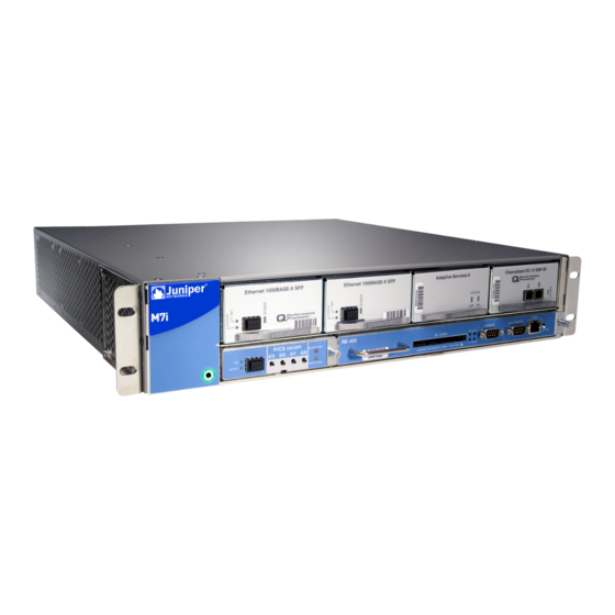
Juniper M7i Hardware Manual
Multiservice edge router
Hide thumbs
Also See for M7i:
- Hardware manual (292 pages) ,
- Quick start manual (23 pages) ,
- Manual (2 pages)

Related Manuals for Juniper M7i


Summary of Contents for Juniper M7i
- Page 1 All manuals and user guides at all-guides.com M7i Multiservice Edge Router Hardware Guide Published: 2010-10-28 Copyright © 2010, Juniper Networks, Inc.
- Page 2 Products made or sold by Juniper Networks or components thereof might be covered by one or more of the following patents that are owned by or licensed to Juniper Networks: U.S. Patent Nos. 5,473,599, 5,905,725, 5,909,440, 6,192,051, 6,333,650, 6,359,479, 6,406,312, 6,429,706, 6,459,579, 6,493,347, 6,538,518, 6,538,899, 6,552,918, 6,567,902, 6,578,186, and 6,590,785.
- Page 3 The information in this document is current as of the date listed in the revision history. YEAR 2000 NOTICE Juniper Networks hardware and software products are Year 2000 compliant. The Junos OS has no known time-related limitations through the year 2038. However, the NTP application is known to have some difficulty in the year 2036.
- Page 4 Juniper, even if such feature, function, service, application, operation, or capability is enabled without a key; (g) distribute any key for the Software provided by Juniper to any third party; (h) use the...
- Page 5 Customer did not originally purchase from Juniper or an authorized Juniper reseller; (k) disclose the results of testing or benchmarking of the Software to any third party without the prior written consent of Juniper; or (l) use the Software in any manner other than as expressly provided herein.
- Page 6 (or services are accessed by) the Software shall be a third party beneficiary with respect to this Agreement, and such licensor or vendor shall have the right to enforce this Agreement in its own name as if it were Juniper. In addition, certain third party software may be provided with the Software and is subject to the accompanying license(s), if any, of its respective owner(s).
-
Page 7: Table Of Contents
M7i CFEB and CFEB-E LEDs ......... . . 14 M7i Fixed Interface Card (FIC) Description ....... 15 M7i FIC LEDs . - Page 8 Verifying the M7i Router Parts Received ....... . . 42...
- Page 9 Maintaining the M7i CFEB and CFEB-E ........
- Page 10 Installing an SFP into an M7i Router ....... . 96...
- Page 11 M7i Router Installation Safety Guidelines and Warnings ....130 M7i Chassis Lifting Guidelines ........131 Installation Safety Warnings for M Series, MX Series, and T Series Routers .
- Page 12 Packing the M7i Router for Shipment ........
- Page 13 Index ............197 Copyright © 2010, Juniper Networks, Inc.
- Page 14 All manuals and user guides at all-guides.com M7i Multiservice Edge Router Hardware Guide Copyright © 2010, Juniper Networks, Inc.
- Page 15 M7i Hardware Components ........
- Page 16 Providing Power to the M7i Router ........
- Page 17 Appendix G Contacting Customer Support and Returning M7i Hardware ... 187 Figure 63: Serial Number ID Label ........188 Figure 64: CFEB or CBEF-E Serial Number ID Label .
- Page 18 All manuals and user guides at all-guides.com M7i Multiservice Edge Router Hardware Guide xviii Copyright © 2010, Juniper Networks, Inc.
- Page 19 Table 6: States for Routing Engine LEDs ....... . . 21 Table 7: States for the M7i Power Supply LED ......24...
- Page 20 M7i Cable Connector Pinouts ........
-
Page 21: About The Documentation
Objectives This documentation describes hardware components, installation, basic configuration, and basic troubleshooting procedures for the Juniper Networks M7i Multiservice Edge Router. It explains how to prepare your site for router installation, unpack and install the hardware, power on the router, perform initial software configuration, and perform routine maintenance. -
Page 22: Audience
Audience This documentation is designed for network administrators who are installing and maintaining a Juniper Networks router or preparing a site for router installation. To use the documentation, you need a broad understanding of networks in general, the Internet in particular, networking principles, and network configuration. Any detailed discussion of these concepts is beyond the scope of this hardware documentation. -
Page 23: Documentation Feedback
Documentation Feedback We encourage you to provide feedback, comments, and suggestions so that we can improve the documentation. You can send your comments to techpubs-comments@juniper.net , or fill out the documentation feedback form at Copyright © 2010, Juniper Networks, Inc. xxiii... -
Page 24: Requesting Technical Support
7 days a week, 365 days a year. Self-Help Online Tools and Resources For quick and easy problem resolution, Juniper Networks has designed an online self-service portal called the Customer Support Center (CSC) that provides you with the following features: Find CSC offerings: http://www.juniper.net/customers/support/... -
Page 25: Opening A Case With Jtac
You can open a case with JTAC on the Web or by telephone. Use the Case Management tool in the CSC at http://www.juniper.net/cm/ Call 1-888-314-JTAC (1-888-314-5822 toll-free in the USA, Canada, and Mexico). For international or direct-dial options in countries without toll-free numbers, see http://www.juniper.net/support/requesting-support.html Copyright © 2010, Juniper Networks, Inc. - Page 26 All manuals and user guides at all-guides.com M7i Multiservice Edge Router Hardware Guide xxvi Copyright © 2010, Juniper Networks, Inc.
-
Page 27: Part 1 Overview Of The M7I Multiservice Edge Router
All manuals and user guides at all-guides.com PART 1 Overview of the M7i Multiservice Edge Router Overview of the M7i Router on page 3 M7i Hardware Components on page 5 System Architecture Overview on page 27 Copyright © 2010, Juniper Networks, Inc. - Page 28 All manuals and user guides at all-guides.com M7i Multiservice Edge Router Hardware Guide Copyright © 2010, Juniper Networks, Inc.
-
Page 29: Overview Of The M7I Router
M7i Router Description on page 3 M7i Router Description The M7i Multiservice Edge Router is a complete routing system that provides ATM, channelized, Ethernet, IP services, and SONET/SDH interfaces for large networks and network applications, such as those supported by Internet service providers (ISPs). - Page 30 All manuals and user guides at all-guides.com M7i Multiservice Edge Router Hardware Guide Copyright © 2010, Juniper Networks, Inc.
-
Page 31: Chapter 2 M7I Hardware Components
M7i Component Redundancy on page 5 M7i Chassis Description on page 6 M7i Midplane Description on page 7 M7i Compact Forwarding Engine Board (CFEB) and Enhanced Compact Forwarding Engine Board (CFEB-E) Description on page 8 M7i CFEB and CFEB-E LEDs on page 14... -
Page 32: M7I Chassis Description
The chassis is 17.5 in. (44.5 cm) wide and 18 in. (45.7 cm) deep. The chassis height of 3.5 in. (8.9 cm) enables stacked installation of 21 M7i routers in a single floor-to-ceiling rack. For more information, see “M7i Router Rack Requirements” on page 36. -
Page 33: M7I Midplane Description
MX Series, and T Series Routers” on page 125 and “General Safety Warnings for M Series, MX Series, and T Series Routers” on page 126. For chassis serial number information , see “Displaying M7i Router Components and Serial Numbers” on page 187. -
Page 34: M7I Compact Forwarding Engine Board (Cfeb) And Enhanced Compact Forwarding Engine Board (Cfeb-E) Description
M7i Compact Forwarding Engine Board (CFEB) and Enhanced Compact Forwarding Engine Board (CFEB-E) Description The M7i Multiservice Edge Router houses either a Compact Forwarding Engine Board (CFEB) or an Enhanced Compact Forwarding Engine Board (CFEB-E), which is located on the rear of the router above the power supplies, as shown in Figure 2 on page 6. It provides route lookup, filtering, and switching on incoming data packets, then directs outbound packets to the appropriate interface for transmission to the network. -
Page 35: Cfeb
All manuals and user guides at all-guides.com Chapter 2: M7i Hardware Components CFEB The CFEB has the following major components: Processing components: 266-MHz CPU and supporting circuitry Integrated ASIC 33-MHz PCI bus Storage components: 128-MB SDRAM for packet memory 128-MB SDRAM for the microkernel... -
Page 36: Cfeb-E
The CFEB-E provides the following additional and enhanced functions: Optional MultiServices Module (MSM)—Provides one or more services on one PIC. See “M7i MultiServices Module” on page 13 for more information. Increased number of logical interfaces. Increased route, nexthop, and interface lookup memory. - Page 37 All manuals and user guides at all-guides.com Chapter 2: M7i Hardware Components Independent EXP and DSCP rewrite Independent Layer 2 and Layer 3 classification on same port The CFEB-E has the following major components: Processing components: 1-GHz CPU and supporting circuitry...
-
Page 38: M7I Adaptive Services Module
All manuals and user guides at all-guides.com M7i Multiservice Edge Router Hardware Guide Figure 6: CFEB-E Figure 7: CFEB-E with Adaptive Services Module Figure 8: CFEB-E with MultiServices Module M7i Adaptive Services Module The Adaptive Services Module is an optional component of the CFEB and CFEB-E. The Adaptive Services Module is similar to the standalone Adaptive Services PIC, but operates Copyright ©... -
Page 39: M7I Multiservices Module
All manuals and user guides at all-guides.com Chapter 2: M7i Hardware Components at a reduced bandwidth. The Adaptive Services Module enables you to perform one or more services on the same PIC by configuring a set of services and applications. -
Page 40: M7I Cfeb And Cfeb-E Leds
Interfaces Configuration Guide. Related M7i CFEB and CFEB-E LEDs on page 14 Documentation M7i and M10i Packet Forwarding Engine Architecture on page 28 M7i Router Description on page 3 M7i Router Physical Specifications on page 159 M7i CFEB and CFEB-E LEDs... -
Page 41: M7I Fixed Interface Card (Fic) Description
See Figure 9 on page 15 and Figure 10 on page 15. For more information about Fast Ethernet and Gigabit Ethernet interfaces, see the M7i Multiservice Edge Router PIC Guide. The networking interface on the FIC is configured the same way as a PIC. -
Page 42: M7I Fic Leds
Related M7i Fixed Interface Card (FIC) Description on page 15 Documentation Connecting FIC and PIC Cables to the M7i Router on page 55 M7i PICs Description PICs physically connect the router to network media. PICs receive incoming packets from the network and transmit outgoing packets to the network, performing framing and line-speed signaling for their media type as required. -
Page 43: M7I Pic Leds
PIC depends on the type of PIC. The M7i router has a maximum throughput of 3.2 Gbps full duplex for the FPC with 4 PIC slots. Inserting a combination of PICs with an aggregate higher than the maximum throughput is supported, but constitutes oversubscription of the FPC. -
Page 44: M7I Flexible Pic Concentrators (Fpcs) Description
Flexible PIC Concentrators (FPCs) house the PICs that connect the router to network media (for information about PICs, see “M7i PICs Description” on page 16). On the M7i router, each FPC is built in (it cannot be removed from the chassis as on other M Series routers). -
Page 45: Boot Sequence
All manuals and user guides at all-guides.com Chapter 2: M7i Hardware Components Figure 12: Routing Engine The Routing Engine (shown in Figure 12 on page 19) is a two-board system with the following components: CPU—Runs Junos OS to maintain the router's routing tables and routing protocols. It has a Pentium-class processor. -
Page 46: M7I Routing Engine Management Ports
100-Mbps connection. For information about the pinouts for the connectors, see “RJ-45 Connector Pinouts for the M7i Routing Engine MGMT Port” on page 181. Figure 13 on page 20 shows the ports that connect to the Routing Engine. -
Page 47: M7I Routing Engine Leds
State Description Green Blinking There is read/write activity on the PC card. Blue On steadily Routing Engine is functioning as master. On an M7i MASTER router, this LED is always lit. On steadily Routing Engine is not operational. FAIL ONLINE... -
Page 48: M7I Ac Power Supply
Power supplies are hot-removable and hot-insertable, as described in “M7I Field-Replaceable Units (FRUs)” on page 85. To avoid electrical injury, carefully follow the instructions in “Replacing an M7i AC Power Supply” on page 106 and “Replacing a DC Power Supply” on page 111. -
Page 49: M7I Dc Power Supply
A DC-powered router has one or two load-sharing DC power supplies, located at the bottom rear of the chassis, as shown in Figure 2 on page 6. For information about power supply redundancy and replaceability, see “M7i Power System Description” on page 21. Figure 15 on page 23 shows the power supply. -
Page 50: M7I Power Supply Leds
Documentation M7i Power System Description on page 21 Replacing an M7i AC Power Supply on page 106 Troubleshooting the M7i Power System When the LED on One M7i Power Supply Is Off on page 81 M7i Cooling System Overview The router cooling system consists of a fan tray, located along the left side of the chassis, that provides side-to-side cooling (see Figure 17 on page 25). -
Page 51: M7I Airflow Through The Chassis
Related Maintaining the M7i Cooling System on page 74 Documentation M7i Router Clearance Requirements for Airflow and Hardware Maintenance on page 38 M7i Router Description on page 3 M7i Cable Management System The cable management system consists of racks that attach vertically to each side of the chassis at the front. - Page 52 All manuals and user guides at all-guides.com M7i Multiservice Edge Router Hardware Guide Copyright © 2010, Juniper Networks, Inc.
-
Page 53: Chapter 3 System Architecture Overview
All manuals and user guides at all-guides.com CHAPTER 3 System Architecture Overview System Architecture Overview on page 27 M7i and M10i Packet Forwarding Engine Architecture on page 28 Routing Engine Architecture on page 29 System Architecture Overview The router architecture consists of two major components: Packet Forwarding Engine—Performs Layer 2 and Layer 3 packet switching, route... -
Page 54: M7I And M10I Packet Forwarding Engine Architecture
All manuals and user guides at all-guides.com M7i Multiservice Edge Router Hardware Guide M7i and M10i Packet Forwarding Engine Architecture The Packet Forwarding Engine performs Layer 2 and Layer 3 packet switching. The Packet Forwarding Engine is implemented in application-specific integrated circuits (ASICs). It uses a centralized route lookup engine and shared memory. -
Page 55: Routing Engine Architecture
M7i Router Description on page 3 Routing Engine Architecture The Routing Engine runs the Junos OS, which Juniper Networks has developed and optimized to handle large numbers of network interfaces and routes. The software consists of a set of system processes running in protected memory modules on top of an independent operating system. -
Page 56: Routing Engine Functions
All manuals and user guides at all-guides.com M7i Multiservice Edge Router Hardware Guide Figure 20: Routing Engine Architecture Routing Engine Functions The Routing Engine handles all routing protocol processes, as well as the software processes that control the router's interfaces, the chassis components, system management, and user access to the router. -
Page 57: Figure 21: Control Packet Handling For Routing And Forwarding Table
Figure 21: Control Packet Handling for Routing and Forwarding Table Updates Related M7i Routing Engine Description on page 18 Documentation Maintaining the M7i Routing Engine on page 72 Replacing the M7i Routing Engine on page 97 Copyright © 2010, Juniper Networks, Inc. - Page 58 All manuals and user guides at all-guides.com M7i Multiservice Edge Router Hardware Guide Copyright © 2010, Juniper Networks, Inc.
-
Page 59: Part 2 Setting Up The M7I Router
All manuals and user guides at all-guides.com PART 2 Setting Up the M7i Router Preparing the Site for M7i Router Installation on page 35 Overview of M7i Router Installation on page 39 Unpacking the M7i Router on page 41 Installing the M7i Router Mounting Hardware on page 45... - Page 60 All manuals and user guides at all-guides.com M7i Multiservice Edge Router Hardware Guide Copyright © 2010, Juniper Networks, Inc.
-
Page 61: Chapter 4 Preparing The Site For M7I Router Installation
M7i Router Site Preparation Checklist on page 35 M7i Router Rack Requirements on page 36 M7i Router Clearance Requirements for Airflow and Hardware Maintenance on page 38 M7i Router Site Preparation Checklist The checklist in Table 8 on page 35 summarizes the tasks you need to perform when preparing a site for router installation. -
Page 62: M7I Router Rack Requirements
The router can be installed in many types of racks, including four-post (telco) racks and open-frame racks. An example of an open-frame rack appears in Figure 22 on page 37.Table 9 on page 36 summarizes rack requirements and specifications for an M7i router. -
Page 63: Figure 22: Typical Open-Frame Rack
Installation Safety Warnings for M Series, MX Series, and T Series Routers on page 131 Documentation M7i Router Clearance Requirements for Airflow and Hardware Maintenance on page 38 M7i Router Physical Specifications on page 159 M7i Router Site Preparation Checklist on page 35... -
Page 64: M7I Router Clearance Requirements For Airflow And Hardware Maintenance
All manuals and user guides at all-guides.com M7i Multiservice Edge Router Hardware Guide M7i Router Clearance Requirements for Airflow and Hardware Maintenance When planning the installation site, you need to allow sufficient clearance around the rack (see Figure 23 on page 38): For the cooling system of side-cooled routers to function properly, the airflow around the chassis must be unrestricted. -
Page 65: Overview Of M7I Router Installation
If you are center-mounting the router, move the mounting brackets as described in “Moving the Mounting Brackets” on page 46. Install the router as described in “Installing the M7i Router Into the Rack” on page 47. Connect the grounding cable as described in “Connecting the Grounding Cable to the M7i Router”... - Page 66 All manuals and user guides at all-guides.com M7i Multiservice Edge Router Hardware Guide M7i Chassis Description on page 6 M7i Chassis Lifting Guidelines on page 131 Copyright © 2010, Juniper Networks, Inc.
-
Page 67: Chapter 6 Unpacking The M7I Router
Unpacking the M7i Router The router is shipped in a cardboard carton, secured with foam packing material. The carton also contains an accessory box and the M7i Internet Router Installation Quick Start. NOTE: The router is maximally protected inside the shipping carton. Do not unpack it until you are ready to begin installation. -
Page 68: Verifying The M7I Router Parts Received
Related M7i Router Description on page 3 Documentation M7i Router Physical Specifications on page 159 M7i Router Rack Requirements on page 36 Verifying the M7i Router Parts Received A packing list is included in each shipment. Check the parts in the shipment against the items on the packing list. -
Page 69: Table 10: Generic Inventory Of Router Components Installed In The M7I Chassis
Table 10 on page 43, and an accessory box, which contains the parts listed in Table 11 on page 43. The parts shipped with your router can vary depending on the configuration you ordered. Table 10: Generic Inventory of Router Components Installed in the M7i Chassis Component... - Page 70 Ethernet cable, RJ-45/RJ-45, 4-pair stranded UTP, Category 5E, 15' ESD wrist strap with cable Related M7i Router Description on page 3 Documentation M7i Router Physical Specifications on page 159 M7i Chassis Description on page 6 Copyright © 2010, Juniper Networks, Inc.
-
Page 71: Chapter 7 Installing The M7I Router Mounting Hardware
CHAPTER 7 Installing the M7i Router Mounting Hardware Installing the M7i Cable Management System on page 45 Moving the Mounting Brackets on page 46 Installing the M7i Cable Management System The cable management system organizes and supports the PIC cables to prevent damage. -
Page 72: Moving The Mounting Brackets
Secure the mounting brackets to the chassis by installing screws along both the front and rear of the brackets. Related Installation Safety Warnings for M Series, MX Series, and T Series Routers on page 131 Documentation Installing the M7i Router Into the Rack on page 47 Copyright © 2010, Juniper Networks, Inc. -
Page 73: Chapter 8 Installing The M7I Router
CHAPTER 8 Installing the M7i Router Tools and Parts Required to Install the M7i Router Into a Rack on page 47 Installing the M7i Router Into the Rack on page 47 Tools and Parts Required to Install the M7i Router Into a Rack... -
Page 74: Figure 26: Installing The Router
M7i Multiservice Edge Router Hardware Guide Review the guidelines in “M7i Chassis Lifting Guidelines” on page 131. Remove the router from the shipping carton, as described in “Unpacking the M7i Router” on page 41. Then, perform the following procedures to install the router: NOTE: If you are installing multiple routers in one rack, install the lowest one first and proceed upward in the rack. - Page 75 Verify that all the mounting screws on one side of the rack are aligned with the mounting screws on the opposite side and that the router is level. To continue the installation, proceed to “Connecting the M7i Router to Management and Alarm Devices” on page 53.
- Page 76 All manuals and user guides at all-guides.com M7i Multiservice Edge Router Hardware Guide Copyright © 2010, Juniper Networks, Inc.
-
Page 77: Grounding The M7I Router
All manuals and user guides at all-guides.com CHAPTER 9 Grounding the M7i Router Connecting the Grounding Cable to the M7i Router on page 51 Connecting the Grounding Cable to the M7i Router To connect the grounding cable: Attach an electrostatic discharge (ESD) grounding strap to your bare wrist, and connect the strap to an approved site ESD grounding point. - Page 78 All manuals and user guides at all-guides.com M7i Multiservice Edge Router Hardware Guide Copyright © 2010, Juniper Networks, Inc.
-
Page 79: Chapter 10 Connecting The M7I Router To External Devices
CHAPTER 10 Connecting the M7i Router to External Devices After installing the router into the rack as described in “Installing the M7i Router Into the Rack” on page 47, complete the installation by performing the procedures described in the following topics:... -
Page 80: Connecting The M7I Router To A Network For Out-Of-Band Management
(EIA-232) serial cable with DB-9/DB-9 connectors. One such cable is provided with the router. If you want to connect a device to both ports, you must supply another cable. See “Routing Engine Interface Cable and Wire Specifications for the M7i Router” on page 179. To connect a management console or auxiliary device: Turn off the power to the console or auxiliary device. -
Page 81: Inserting An Sfp Into The 1-Port Gigabit Ethernet Fic
M7i Router Site Preparation Checklist on page 35 Initially Configuring the M7i Router on page 63 Connecting Power to an AC-Powered M7i Router on page 57 Connecting Power to a DC-Powered Router on page 57 Inserting an SFP into the 1-port Gigabit Ethernet FIC Before inserting cables into the 1-port Gigabit Ethernet FIC, you must install a small form-factor pluggable (SFP). -
Page 82: Figure 30: Attaching The Cable To A Pic
30 on page 56, which shows a fiber-optic PIC): Have ready a length of the type of cable used by the FIC or PIC, as specified in “FIC Specifications for the M7i Router” on page 173 or the M7i Multiservice Edge Router PIC Guide. -
Page 83: Chapter 11 Providing Power To The M7I Router
To connect power to an AC-powered router: Locate the power cords shipped with the router, which should have a plug appropriate for your geographical location (see “M7i Router AC Power, Connection, and Power Cord Specifications” on page 164). Attach an electrostatic discharge (ESD) grounding strap to your bare wrist, and connect the strap to one of the ESD points on the chassis. - Page 84 All manuals and user guides at all-guides.com M7i Multiservice Edge Router Hardware Guide NOTE: The router must be connected to at least two separate external DC power sources. CAUTION: There is no standard color coding for DC power cables. The color...
-
Page 85: Powering On The M7I Router
). For more information AUX/MODEM CONSOLE MGMT on connecting management devices, see “Connecting the M7i Router to Management and Alarm Devices” on page 53. Turn on the power to the external management device. Press the power switch for one power supply to the ) position. -
Page 86: Powering Off The M7I Router
On the external management device connected to the Routing Engine, monitor the startup process to verify that the system has booted properly. Related Troubleshooting the M7i Power System When the LED on One M7i Power Supply Is Off Documentation on page 81... - Page 87 All manuals and user guides at all-guides.com Chapter 11: Providing Power to the M7i Router For more information about the command, see the Junos OS System Basics and Services Command Reference. NOTE: The CFEB might continue forwarding traffic for approximately 5 minutes after the request system halt command has been issued.
- Page 88 All manuals and user guides at all-guides.com M7i Multiservice Edge Router Hardware Guide Copyright © 2010, Juniper Networks, Inc.
-
Page 89: Chapter 12 Configuring Junos Os
The router is shipped with the Junos OS preinstalled and ready to be configured when the router is powered on. The default boot order for the M7i Multiservice Edge Router is different from other Juniper Networks routers, because the default configuration of the Routing Engine on the M7i router does not include an CompactFlash card. - Page 90 For complete information about enabling the router to forward traffic, including examples, see the Junos OS configuration guides. To configure the software: Verify that the router is powered on as described in “Powering on the M7i Router” on page 59. Log in as the “root” user. There is no password.
- Page 91 (the first rollback rescue.conf juniper.conf.1 configuration file). When the search finds the first configuration file that can be loaded properly, the file loads and the search ends. If none of the file can be loaded properly, Copyright © 2010, Juniper Networks, Inc.
- Page 92 If the router boots from an alternate boot device, the Junos OS displays a message indication this when you log in to the router. Related M7i Router Description on page 3 Documentation Overview of M7i Router Installation on page 39 Copyright © 2010, Juniper Networks, Inc.
- Page 93 All manuals and user guides at all-guides.com PART 3 Hardware Maintenance, Troubleshooting, and Replacement Procedures Maintaining M7i Router Hardware Components on page 69 Troubleshooting M7i Hardware Components on page 75 Replacing M7i Hardware Components on page 85 Copyright © 2010, Juniper Networks, Inc.
- Page 94 All manuals and user guides at all-guides.com M7i Multiservice Edge Router Hardware Guide Copyright © 2010, Juniper Networks, Inc.
-
Page 95: Chapter 13 Maintaining M7I Router Hardware Components
Routine Maintenance Procedures for the M7i Router on page 69 Maintaining the M7i CFEB and CFEB-E on page 69 Maintaining the M7i FIC and FIC Cables and PICs and PIC Cables on page 70 Maintaining the M7i Routing Engine on page 72... -
Page 96: Maintaining The M7I Fic And Fic Cables And Pics And Pic Cables
Action Check the LEDs on the FIC faceplate. The Fast Ethernet and Gigabit Ethernet ports on the FIC have LEDs that display the status of the ports. For more information, see “M7i Fixed Interface Card (FIC) Description” on page 15. - Page 97 All manuals and user guides at all-guides.com Chapter 13: Maintaining M7i Router Hardware Components differs for various PICs. For more information, see the M7i Multiservice Edge Router PIC Guide. Issue the CLI show chassis fpc pic-status command. The following example specifies an FPC slot number ( ), which is optional.
-
Page 98: Maintaining The M7I Routing Engine
Check the LEDs on the Routing Engine. The green LED labeled ONLINE lights steadily when it is functioning normally. For more information about the LEDs, see “M7i Routing Engine Description” on page 18. Issue the CLI command to check the status of the Routing... - Page 99 Related M7i Power System Description on page 21 Documentation M7i Router Power Requirements on page 163 Troubleshooting the M7i Power System When the LED on One M7i Power Supply Is Off on page 81 Copyright © 2010, Juniper Networks, Inc.
-
Page 100: Maintaining The M7I Cooling System
All manuals and user guides at all-guides.com M7i Multiservice Edge Router Hardware Guide Troubleshooting the M7i Power System When the LEDs on All M7i Power Supplies Are Blinking or Off on page 81 Maintaining the M7i Cooling System Purpose For optimum cooling, verify the condition of the fans. -
Page 101: Chapter 14 Troubleshooting M7I Hardware Components
CLI to determine the cause of the alarm. For more information about the alarm LEDs, see “M7i Fixed Interface Card (FIC) Description” on page 15. For more information about the causes of alarms, see “Hardware and Interface Alarm Messages” on page 76. -
Page 102: Leds On Hardware Components
PIC faceplate. Some PICs have STATUS additional LEDs, often one per port. The meaning of the LED states differs for various PICs. For more information, see the M7i Multiservice Edge Router PIC Guide. CFEB or CFEB-E—A green LED labeled , a red one labeled... - Page 103 All manuals and user guides at all-guides.com Chapter 14: Troubleshooting M7i Hardware Components Table 12: Chassis Alarm Messages (continued) Chassis Alarm Component Alarm Condition Remedy Severity CFEB/CFEB-E CFEB/CFEB-E has failed. If this Replace failed occurs, the board attempts to reboot.
- Page 104 All manuals and user guides at all-guides.com M7i Multiservice Edge Router Hardware Guide Table 12: Chassis Alarm Messages (continued) Chassis Alarm Component Alarm Condition Remedy Severity Routing Engine Error in reading or writing hard disk. Reformat hard disk Yellow and install bootable image.
-
Page 105: Table 13: Sonet/Sdh Interface Alarm Messages
All manuals and user guides at all-guides.com Chapter 14: Troubleshooting M7i Hardware Components Table 12: Chassis Alarm Messages (continued) Chassis Alarm Component Alarm Condition Remedy Severity Temperature The chassis temperature has Check room Yellow exceeded 55° C and the fans have temperature. -
Page 106: Troubleshooting The M7I Cfeb And Cfeb-E
- SONET remote error indicator interface-name so-x/x/x - SONET severely errored frame interface-name so-x/x/x - SONET unequipped Related Displaying M7i Router Components and Serial Numbers on page 187 Documentation M7i Midplane Description on page 7 M7i Router Description on page 3... -
Page 107: Troubleshooting The M7I Power System
For further description of the output from the command, see the Junos OS System Basics and Services Command Reference. Related Maintaining the M7i FIC and FIC Cables and PICs and PIC Cables on page 70 Documentation Replacing an M7i FIC or PIC Cable on page 92... -
Page 108: Troubleshooting The M7I Fan Tray
You might also try replacing the AC power cord (on an AC-powered router) or DC power cables (on a DC-powered router). For instructions, see Replacing an AC Power Cord and “Replacing an M7i DC Power Cable” on page 115 (you do not need to disconnect and reconnect the grounding cable). - Page 109 See “Troubleshooting the M7i Power System When the LEDs on All M7i Power Supplies Are Blinking or Off” on page 81. If the fan tray has failed, it must be replaced for the router to operate normally. For replacement instructions, see “Replacing the M7i Fan Tray”...
- Page 110 All manuals and user guides at all-guides.com M7i Multiservice Edge Router Hardware Guide Copyright © 2010, Juniper Networks, Inc.
-
Page 111: Chapter 15 Replacing M7I Hardware Components
M7I Field-Replaceable Units (FRUs) on page 85 Tools and Parts Required to Replace M Series Hardware Components on page 86 Replacing, Upgrading, and Downgrading the M7i CFEB and CFEB-E on page 86 Replacing an M7i PIC on page 89 Replacing an M7i FIC or PIC Cable on page 92... -
Page 112: Tools And Parts Required To Replace M Series Hardware Components
The CFEB and CFEB-E are hot-pluggable when you replace a CFEB with a CFEB or a CFEB-E with a CFEB-E, as described in “M7I Field-Replaceable Units (FRUs)” on page 85. Upgrading or downgrading a CFEB device requires a system reboot, as described in... -
Page 113: Removing The M7I Cfeb And Cfeb-E
“Upgrading and Downgrading the CFEB and CFEB-E” on page 88. To replace the CFEB or CFEB-E, perform the following procedures: Removing the M7i CFEB and CFEB-E on page 87 Installing the M7i CFEB and CFEB-E on page 88 Upgrading and Downgrading the CFEB and CFEB-E on page 88... -
Page 114: Installing The M7I Cfeb And Cfeb-E
CFEB requires a system reboot after swapping the CFEB devices. To upgrade from a CFEB to a CFEB-E or downgrade from a CFEB-E to a CFEB: Remove the CFEB or CFEB-E as described in “Removing the M7i CFEB and CFEB-E” on page 87. -
Page 115: Replacing An M7I Pic
Chapter 15: Replacing M7i Hardware Components After the reboot, the router recognizes the new CFEB or CFEB-E. Related Preventing Electrostatic Discharge Damage to an M7i Router on page 128 Documentation Maintaining the M7i CFEB and CFEB-E on page 69 Troubleshooting the M7i CFEB and CFEB-E on page 80 Replacing an M7i PIC PICs are housed in the front of the router, as shown in Figure 1 on page 6. -
Page 116: Installing An M7I Pic
Press and hold the PIC offline button on the FIC until its failure indicator LED lights, which usually takes about 5 seconds. The failure LED is usually red; for more information, see the M7i Multiservice Edge Router PIC Guide. Disconnect the cables from the PIC. If the PIC uses fiber-optic cable, immediately cover each transceiver and the end of each cable with a rubber safety cap. - Page 117 M7i Multiservice Edge Router PIC Guide. You can verify correct PIC functioning by issuing the command, show chassis fpc pic-status described in “Maintaining the M7i FIC and FIC Cables and PICs and PIC Cables” on page 70. Copyright © 2010, Juniper Networks, Inc.
-
Page 118: Replacing An M7I Fic Or Pic Cable
PIC does not receive or transmit data while its cable is disconnected. To replace a PIC cable, perform the following procedures: Removing an M7i FIC or PIC Cable on page 92 Installing an M7i FIC or PIC Cable on page 93... -
Page 119: Installing An M7I Fic Or Pic Cable
If removing all cables connected to the interface, press and hold the PIC offline button on the FIC until its failure indicator LED lights, which usually takes about 5 seconds. The failure LED is usually red; for more information, see the M7i Multiservice Edge Router PIC Guide. -
Page 120: Replacing An Sfp On An M7I Router
M7i Flexible PIC Concentrators (FPCs) Description on page 18 Documentation M7i PICs Description on page 16 Maintaining the M7i FIC and FIC Cables and PICs and PIC Cables on page 70 Troubleshooting the M7i FIC or PICs on page 80 Replacing an SFP on an M7i Router Small form-factor pluggables (SFPs) are optical transceivers that can be removed from a PIC (for more information, see “M7i PICs Description”... -
Page 121: Removing An Sfp From An M7I Router
All manuals and user guides at all-guides.com Chapter 15: Replacing M7i Hardware Components Removing an SFP from an M7i Router WARNING: Do not look directly into transceivers or into the ends of fiber-optic cables connected to a transceiver. Fiber-optic transceivers emit laser light that can damage your eyes. -
Page 122: Installing An Sfp Into An M7I Router
Figure 37: Small Form-Factor Pluggable (SFP) Connector Locking pin Installing an SFP into an M7i Router WARNING: Do not look directly into transceivers or into the ends of fiber-optic cables connected to a transceiver. Fiber-optic transceivers emit laser light that can damage your eyes. -
Page 123: Replacing The M7I Routing Engine And Routing Engine Components
Verify that the status LEDs on the PIC faceplate indicate that the SFP is functioning correctly (there is an LED for each SFP port). For more information about the PIC LEDs, see the M7i Multiservice Edge Router PIC Guide. You can also verify PIC functioning by issuing the command described in “Maintaining the M7i... -
Page 124: Removing An M7I Routing Engine
Figure 39: Removing the Routing Engine Installing the Routing Engine in a M7i Router To install the Routing Engine (see Figure 40 on page 99): Attach an electrostatic discharge (ESD) grounding strap to your bare wrist and connect the strap to one of the ESD points on the chassis. -
Page 125: Replacing The Routing Engine Interface Port Cables
“Maintaining the M7i Routing Engine” on page 72. Figure 40: Installing the Routing Engine Related Preventing Electrostatic Discharge Damage to an M7i Router on page 128 Documentation M7i Chassis Description on page 6 M7i Routing Engine Description on page 18... -
Page 126: Replacing The Console Or Auxiliary Cable
FIC Specifications for the M7i Router on page 173 Removing and Inserting the CompactFlash Card The CompactFlash card is an optional component of the M7i router. If installed, it provides primary storage for the router. It can accommodate software images, configuration files, and microcode. -
Page 127: Removing The Compactflash Card From A Routing Engine
45 on page 102). Use needlenose pliers with grooved jaws to lower and secure the wire clasp. Install the Routing Engine as described in “Installing the Routing Engine in a M7i Router” on page 98. Copyright © 2010, Juniper Networks, Inc. -
Page 128: Configuring The Compactflash Card
To copy software to the CompactFlash card: Install the CompactFlash card and replace the Routing Engine as described in “Inserting the CompactFlash Card” on page 101 and “Installing the Routing Engine in a M7i Router” on page 98. On the console or other management device connected to the Routing Engine, enter... -
Page 129: Removing And Inserting Sdram Modules
Pressing firmly on both ends, push the module into the slot until the ejectors return completely to the closed position. Install the Routing Engine as described in “Installing the Routing Engine in a M7i Router” on page 98. Copyright © 2010, Juniper Networks, Inc. -
Page 130: Removing And Inserting The Pc Card
PC card, for example, to create a backup copy of upgrade software that you have obtained from Juniper Networks. Instructions for copying software to a PC card are available at the Juniper Networks Customer Support Center Web site );... -
Page 131: Removing The Pc Card
All manuals and user guides at all-guides.com Chapter 15: Replacing M7i Hardware Components Removing the PC Card The PC card is inserted in the slot labeled in the Routing Engine faceplate. To PC CARD remove the PC card (see Figure 47 on page 105): Press the eject button located to the right of the PC card slot in the Routing Engine faceplate. -
Page 132: Inserting The Pc Card
Inserting the PC Card To insert the PC card (see Figure 49 on page 106): Orient the PC card with the Juniper Networks logo facing in the direction specified on the Routing Engine faceplate. Insert the card into the slot. -
Page 133: Removing An M7I Ac Power Supply
Before removing the AC power supply from an M7i router with only one power supply, you must power off the router. See “Powering Off the M7i Router” on page 60. The AC power supplies are located at the bottom rear of the chassis, as shown in Figure 2 on page 6. -
Page 134: Installing An M7I Ac Power Supply
) position. Locate the power cord shipped with the router, which should be appropriate for your geographical location (see “M7i Router AC Power, Connection, and Power Cord Specifications” on page 164). Attach an electrostatic discharge (ESD) grounding strap to your bare wrist and connect the strap to one of the ESD points on the chassis. -
Page 135: Replacing An M7I Ac Power Cord
If the Routing Engine finishes booting and you need to power off the router again, see “Powering Off the M7i Router” on page 60. After a power supply is powered on, it can take up to 60 seconds for status indicators—such as the output status LED on the power supply, the... -
Page 136: Removing An M7I Ac Power Cord
Removing an M7i AC Power Cord Before removing the AC power cord from an M7i router with only one power supply, you must power off the router. See “Powering Off the M7i Router” on page 60. To remove the AC power cord: Press the power switch on each power supply faceplate to the ) position. -
Page 137: Replacing A Dc Power Supply
NOTE: If the Routing Engine finishes booting and you need to power off the router again, see “Powering Off the M7i Router” on page 60. After powering off a power supply, wait at least 60 seconds before turning it back on. -
Page 138: Removing A Dc Power Supply
Before removing a DC power supply from an M7i router with only one power supply, you must power off the router. See “Powering Off the M7i Router” on page 60. The DC power supplies are located at the bottom rear of the chassis, as shown in Figure 2 on page 6. -
Page 139: Installing A Dc Power Supply
All manuals and user guides at all-guides.com Chapter 15: Replacing M7i Hardware Components Figure 52: Removing a DC Power Supply Installing a DC Power Supply To install a DC power supply (see Figure 53 on page 114 and Figure 54 on page 115): Verify that there is no power flowing to the power supply from the external power source, so that the voltage across the leads of the power cables is 0 V. -
Page 140: Figure 53: Installing A Dc Power Supply
NOTE: After powering on a power supply, wait at least 60 seconds before turning it off. If the M7I has only one power supply or the router is completely powered off when you power on the power supply, the Routing Engine boots as the power supply completes its startup sequence. -
Page 141: Replacing An M7I Dc Power Cable
Installing an M7i DC Power Cable on page 116 Removing an M7I DC Power Cable Before removing a DC power cable from an M7i router with only one power supply, you must power off the router. To remove a DC power cable from the router: Shut off the power flowing from the external power sources, so that the voltage across the leads of the power cables is 0 V. -
Page 142: Installing An M7I Dc Power Cable
Installing an M7i DC Power Cable For information about the required DC power cables, see “M7i DC Power Cable and Cable Lug Specifications” on page 168. CAUTION: There is no standard color coding for DC power cables. The color... -
Page 143: Replacing The M7I Fan Tray
DC Power Electrical Safety Warnings for M Series, MX Series, and T Series Routers on Documentation page 150 M7i Router DC Power Supply Specifications on page 170 M7i DC Power Electrical Safety Guidelines on page 149 Replacing the M7i Fan Tray... -
Page 144: Installing The M7I Fan Tray
All manuals and user guides at all-guides.com M7i Multiservice Edge Router Hardware Guide CAUTION: To avoid injury, do not touch the fans with your fingers or any tool as you slide the fan tray out of the chassis—they might still be spinning. -
Page 145: Figure 57: Installing The Fan Tray
Chapter 15: Replacing M7i Hardware Components Figure 57: Installing the Fan Tray Related M7i Cooling System Overview on page 24 Documentation M7i Chassis Description on page 6 Troubleshooting the M7i Fan Tray on page 82 Copyright © 2010, Juniper Networks, Inc. - Page 146 All manuals and user guides at all-guides.com M7i Multiservice Edge Router Hardware Guide Copyright © 2010, Juniper Networks, Inc.
-
Page 147: Appendixes
M7i Router Environmental Specifications on page 161 Power Guidelines, Requirements, and Specifications for the M7i Router on page 163 Cable and Wire Guidelines and Specifications for the M7i Router on page 173 M7i Cable Connector Pinouts on page 181 Contacting Customer Support and Returning M7i Hardware on page 187... - Page 148 All manuals and user guides at all-guides.com M7i Multiservice Edge Router Hardware Guide Copyright © 2010, Juniper Networks, Inc.
-
Page 149: Appendix A Safety And Regulatory Compliance Information For The M7I Router
Definition of Safety Warning Levels on page 123 Safety Guidelines and Warnings for the M7i Router on page 125 Agency Approvals and Compliance Statements for the M7i Router on page 153 Definition of Safety Warning Levels The M Series, MX Series, and T Series router documentation uses the following levels of... - Page 150 All manuals and user guides at all-guides.com M7i Multiservice Edge Router Hardware Guide Varoitus Tämä varoitusmerkki merkitsee vaaraa. Olet tilanteessa, joka voi johtaa ruumiinvammaan. Ennen kuin työskentelet minkään laitteiston parissa, ota selvää sähkökytkentöihin liittyvistä vaaroista ja tavanomaisista onnettomuuksien ehkäisykeinoista. Attention Ce symbole d'avertissement indique un danger. Vous vous trouvez dans une situation pouvant causer des blessures ou des dommages corporels.
-
Page 151: Safety Guidelines And Warnings For The M7I Router
Fire Safety Requirements for M Series, MX Series, and T Series Routers on page 129 M7i Router Installation Safety Guidelines and Warnings on page 130 Laser and LED Safety Guidelines and Warnings for the M7i Router on page 136 Maintenance and Operational Safety Warnings for M Series, MX Series, and T Series... -
Page 152: General Safety Warnings For M Series, Mx Series, And T Series Routers
All manuals and user guides at all-guides.com M7i Multiservice Edge Router Hardware Guide Do not push or force any objects through any opening in the chassis frame. Such an action could result in electrical shock or fire. Avoid spilling liquid onto the chassis or onto any router component. Such an action could cause electrical shock or damage the router. -
Page 153: Restricted Access Area Warning
All manuals and user guides at all-guides.com Appendix A: Safety and Regulatory Compliance Information for the M7i Router Restricted Access Area Warning WARNING: The router is intended for installation in restricted access areas. A restricted access area is an area to which access can be gained only by... -
Page 154: Preventing Electrostatic Discharge Damage To An M7I Router
DC Power Electrical Safety Warnings for M Series, MX Series, and T Series Routers on page 150 Preventing Electrostatic Discharge Damage to an M7i Router Many router hardware components are sensitive to damage from static electricity. Some components can be impaired by voltages as low as 30 V. You can easily generate potentially damaging static voltages whenever you handle plastic or foam packing material or if you move components across plastic or carpets. -
Page 155: Fire Safety Requirements For M Series, Mx Series, And T Series Routers
All manuals and user guides at all-guides.com Appendix A: Safety and Regulatory Compliance Information for the M7i Router Figure 58: Placing a Component into an Electrostatic Bag Related Definition of Safety Warning Levels on page 123 Documentation General Safety Warnings for M Series, MX Series, and T Series Routers on page 126... -
Page 156: Fire Suppression Equipment
NOTE: To keep warranties effective, do not use a dry chemical fire extinguisher to control a fire at or near a Juniper Networks router. If a dry chemical fire extinguisher is used, the unit is no longer eligible for coverage under a service agreement. -
Page 157: M7I Chassis Lifting Guidelines
The weight of a fully configured chassis is about 36.5 lb (16.6 kg). Observe the following guidelines for lifting and moving the router: Before moving the router, read the guidelines in “M7i Router Site Preparation Checklist” on page 35 to verify that the intended site meets the specified power, environmental, and clearance requirements. - Page 158 All manuals and user guides at all-guides.com M7i Multiservice Edge Router Hardware Guide ¡Atención! Ver las instrucciones de instalación antes de conectar el sistema a la red de alimentación. Varning! Läs installationsanvisningarna innan du kopplar systemet till dess strömförsörjningsenhet. Rack-Mounting Requirements and Warnings...
- Page 159 All manuals and user guides at all-guides.com Appendix A: Safety and Regulatory Compliance Information for the M7i Router Router on asennettava telineeseen, joka on kiinnitetty rakennukseen. Jos telineessä ei ole muita laitteita, aseta laite telineen alaosaan. Jos laite asetetaan osaksi täytettyyn telineeseen, aloita kuormittaminen sen alaosasta kaikkein raskaimmalla esineellä...
- Page 160 All manuals and user guides at all-guides.com M7i Multiservice Edge Router Hardware Guide Il router deve essere installato in un telaio, il quale deve essere fissato alla struttura dell'edificio. Questa unità deve venire montata sul fondo del supporto, se si tratta dell'unica unità...
- Page 161 All manuals and user guides at all-guides.com Appendix A: Safety and Regulatory Compliance Information for the M7i Router El router debe instalarse en un bastidor fijado a la estructura del edificio. Colocar el equipo en la parte inferior del bastidor, cuando sea la única unidad en el mismo.
-
Page 162: Laser And Led Safety Guidelines And Warnings For The M7I Router
Maintenance and Operational Safety Warnings for M Series, MX Series, and T Series Routers on page 139 Laser and LED Safety Guidelines and Warnings for the M7i Router General Laser Safety Guidelines for the M7i Router on page 136 M7i Laser and LED Safety Warnings on page 136... - Page 163 All manuals and user guides at all-guides.com Appendix A: Safety and Regulatory Compliance Information for the M7i Router Avvertenza Prodotto laser di Classe 1. Advarsel Laserprodukt av klasse 1. Aviso Produto laser de classe 1. ¡Atención! Producto láser Clase I.
- Page 164 All manuals and user guides at all-guides.com M7i Multiservice Edge Router Hardware Guide Advarsel Stirr eller se ikke direkte p strlen med optiske instrumenter. Aviso Não olhe fixamente para o raio, nem olhe para ele directamente com instrumentos ópticos. ¡Atención! No mirar fijamente el haz ni observarlo directamente con instrumentos ópticos.
-
Page 165: Maintenance And Operational Safety Warnings For M Series, Mx Series, And T Series Routers
All manuals and user guides at all-guides.com Appendix A: Safety and Regulatory Compliance Information for the M7i Router Varning! Osynlig strålning kan avges från en portöppning utan ansluten fiberkabel och du bör därför undvika att bli utsatt för strålning genom att inte stirra in i oskyddade öppningar. -
Page 166: Jewelry Removal Warning
All manuals and user guides at all-guides.com M7i Multiservice Edge Router Hardware Guide Advarsel Det kan være fare for eksplosjon hvis batteriet skiftes på feil måte. Skift kun med samme eller tilsvarende type som er anbefalt av produsenten. Kasser brukte batterier i henhold til produsentens instruksjoner. -
Page 167: Lightning Activity Warning
All manuals and user guides at all-guides.com Appendix A: Safety and Regulatory Compliance Information for the M7i Router Avvertenza Prima di intervenire su apparecchiature collegate alle linee di alimentazione, togliersi qualsiasi monile (inclusi anelli, collane, braccialetti ed orologi). Gli oggetti metallici si riscaldano quando sono collegati tra punti di alimentazione e massa: possono causare ustioni gravi oppure il metallo può... -
Page 168: Operating Temperature Warning
All manuals and user guides at all-guides.com M7i Multiservice Edge Router Hardware Guide Advarsel Utfør aldri arbeid på systemet, eller koble kabler til eller fra systemet når det tordner eller lyner. Aviso Não trabalhe no sistema ou ligue e desligue cabos durante períodos de mau tempo (trovoada). -
Page 169: Product Disposal Warning
All manuals and user guides at all-guides.com Appendix A: Safety and Regulatory Compliance Information for the M7i Router ο ο overstiger 40 C (104 F). Sørg for at klaringen rundt lufteåpningene er minst 15,2 cm (6 tommer) for å forhindre nedsatt luftsirkulasjon. -
Page 170: Electrical Safety Guidelines And Warnings For The M7I Router
T Series Routers on page 148 In Case of an Electrical Accident on page 148 M7i AC Power Electrical Safety Guidelines and Warnings on page 149 M7i DC Power Electrical Safety Guidelines on page 149 DC Power Electrical Safety Warnings for M Series, MX Series, and T Series... - Page 171 All manuals and user guides at all-guides.com Appendix A: Safety and Regulatory Compliance Information for the M7i Router Aviso Este equipamento deverá estar ligado à terra. Certifique-se que o host se encontra ligado à terra durante a sua utilização normal.
- Page 172 All manuals and user guides at all-guides.com M7i Multiservice Edge Router Hardware Guide Midplane Energy Hazard Warning WARNING: High levels of electrical energy are distributed across the router midplane. Be careful not to contact the midplane connectors, or any component connected to the midplane, with any metallic object while servicing components installed in the router.
- Page 173 All manuals and user guides at all-guides.com Appendix A: Safety and Regulatory Compliance Information for the M7i Router Power Disconnection Warning WARNING: Before working on the chassis or near power supplies, switch off the power at the DC circuit breaker.
-
Page 174: General Electrical Safety Guidelines And Electrical Codes For M Series, Mx Series, And T Series Routers
General Electrical Safety Guidelines and Electrical Codes for M Series, MX Series, and Documentation T Series Routers on page 148 M7i AC Power Electrical Safety Guidelines and Warnings on page 149 M7i DC Power Electrical Safety Guidelines on page 149 Copyright © 2010, Juniper Networks, Inc. -
Page 175: M7I Ac Power Electrical Safety Guidelines And Warnings
All manuals and user guides at all-guides.com Appendix A: Safety and Regulatory Compliance Information for the M7i Router M7i AC Power Electrical Safety Guidelines and Warnings The following electrical safety guidelines apply to AC-powered routers: AC-powered routers are shipped with a three-wire electrical cord with a grounding-type plug that fits only a grounding-type power outlet. -
Page 176: Dc Power Electrical Safety Warnings For M Series, Mx Series, And T Series Routers
All manuals and user guides at all-guides.com M7i Multiservice Edge Router Hardware Guide Be sure to connect the ground wire or conduit to a solid office (earth) ground. A closed loop ring is recommended for terminating the ground conductor at the ground stud. - Page 177 All manuals and user guides at all-guides.com Appendix A: Safety and Regulatory Compliance Information for the M7i Router Advarsel Bruk bare kobberledninger. Aviso Utilize apenas fios condutores de cobre. ¡Atención! Emplee sólo conductores de cobre. Varning! Använd endast ledare av koppar.
- Page 178 All manuals and user guides at all-guides.com M7i Multiservice Edge Router Hardware Guide Advarsel Før noen av disse prosedyrene utføres, kontroller at strømmen er frakoblet likestrømkretsen. Sørg for at all strøm er slått AV. Dette gjøres ved å lokalisere strømbryteren på brytertavlen som betjener likestrømkretsen, slå...
-
Page 179: Agency Approvals And Compliance Statements For The M7I Router
Agency Approvals for M7i Routers on page 154 Compliance Statements for NEBS for M Series, MX Series, and T Series Routers on page 155 Compliance Statements for EMC Requirements for the M7i Router on page 155 Copyright © 2010, Juniper Networks, Inc. -
Page 180: Agency Approvals For M7I Routers
Compliance Statements for Environmental Requirements for M Series, MX Series, and T Series Routers on page 157 Compliance Statements for Acoustic Noise for the M7i Router on page 157 Agency Approvals for M7i Routers The router complies with the following standards: Safety CAN/CSA-22.2 No. -
Page 181: Compliance Statements For Nebs For M Series, Mx Series, And T Series Routers
Compliance Statements for NEBS for M Series, MX Series, and T Series Routers on Documentation page 155 Compliance Statements for EMC Requirements for the M7i Router on page 155 Compliance Statements for Environmental Requirements for M Series, MX Series, and T Series Routers on page 157... -
Page 182: Declaration Of Conformity
Compliance Statements for NEBS for M Series, MX Series, and T Series Routers on page 155 Compliance Statements for Environmental Requirements for M Series, MX Series, and T Series Routers on page 157 Compliance Statements for Acoustic Noise for the M7i Router on page 157 Copyright © 2010, Juniper Networks, Inc. -
Page 183: Compliance Statements For Emc Requirements For M Series, Mx Series, And T Series Routers (United States)
All manuals and user guides at all-guides.com Appendix A: Safety and Regulatory Compliance Information for the M7i Router Compliance Statements for EMC Requirements for M Series, MX Series, and T Series Routers (United States) The router has been tested and found to comply with the limits for a Class A digital device, pursuant to Part 15 of the FCC Rules. - Page 184 Compliance Statements for NEBS for M Series, MX Series, and T Series Routers on page 155 Compliance Statements for EMC Requirements for the M7i Router on page 155 Compliance Statements for Environmental Requirements for M Series, MX Series, and T Series Routers on page 157...
-
Page 185: Appendix B M7I Router Physical Specifications
All manuals and user guides at all-guides.com APPENDIX B M7i Router Physical Specifications M7i Router Physical Specifications on page 159 M7i Router Physical Specifications Table 16 on page 159 summarizes the physical specifications for the router chassis. Table 16: Chassis Physical Specifications... - Page 186 All manuals and user guides at all-guides.com M7i Multiservice Edge Router Hardware Guide Related M7i Router Environmental Specifications on page 161 Documentation M7i Router Power Requirements on page 163 M7i Router Description on page 3 Copyright © 2010, Juniper Networks, Inc.
-
Page 187: Appendix C M7I Router Environmental Specifications
All manuals and user guides at all-guides.com APPENDIX C M7i Router Environmental Specifications M7i Router Environmental Specifications on page 161 M7i Router Environmental Specifications Table 17 on page 161 specifies the environmental conditions required for normal router operation. In addition, the site should be as dust-free as possible. Dust can clog air intake vents and filters, reducing cooling system efficiency. - Page 188 All manuals and user guides at all-guides.com M7i Multiservice Edge Router Hardware Guide M7i Router Power Requirements on page 163 M7i Router Description on page 3 Copyright © 2010, Juniper Networks, Inc.
-
Page 189: Router
Routing Engine 0.7 A You can use the information in Table 18 on page 163 and the M7i Multiservice Edge Router PIC Guide to calculate power consumption for various hardware configurations, input current from a different source voltage, and thermal output, as shown in the following examples. -
Page 190: M7I Router Ac Power Specifications And Requirements
Site Electrical Wiring Guidelines for M Series, MX Series, and T Series Routers on page 170 M7i Router AC Power Specifications and Requirements M7i Router AC Power, Connection, and Power Cord Specifications on page 164 M7i Router AC Power Supply Specifications on page 166 M7i Router AC Power, Connection, and Power Cord Specifications Detachable AC power cords, each 2.5 m (approximately 8 ft) long, are supplied with the... -
Page 191: Table 19: Ac Power Cord Specifications
All manuals and user guides at all-guides.com Appendix D: Power Guidelines, Requirements, and Specifications for the M7i Router WARNING: Translation from Japanese: The attached power cable is only for this product. Do not use the cable for another product. NOTE: In North America, AC power cords must not exceed 4.5 m (approximately 14.75 ft) in length, to comply with National Electrical Code... -
Page 192: M7I Router Ac Power Supply Specifications
Related M7i AC Power Supply on page 22 Documentation Connecting Power to an AC-Powered M7i Router on page 57 Replacing an M7i AC Power Supply on page 106 Replacing an AC Power Cord M7i Router Power Requirements on page 163... -
Page 193: M7I Router Dc Power Specifications And Requirements
Replacing an AC Power Cord M7i Router Power Requirements on page 163 M7i Router AC Power, Connection, and Power Cord Specifications on page 164 M7i Router DC Power Specifications and Requirements M7i Chassis Grounding, Connection, and Cable Specifications on page 167... -
Page 194: M7I Dc Power Cable And Cable Lug Specifications
Figure 61: Grounding Cable Connection Related M7i Chassis Description on page 6 Documentation Connecting the Grounding Cable to the M7i Router on page 51 M7i DC Power Cable and Cable Lug Specifications DC Power Cables on page 168 DC Power Lugs on page 169... -
Page 195: Dc Power Lugs
All manuals and user guides at all-guides.com Appendix D: Power Guidelines, Requirements, and Specifications for the M7i Router WARNING: For field-wiring connections, use copper conductors only. For other electrical safety information, see . NOTE: Power cords and cables must not block access to router components or drape where people could trip on them. -
Page 196: M7I Router Dc Power Supply Specifications
Replacing an M7i DC Power Cable on page 115 M7i Router Power Requirements on page 163 M7i Chassis Grounding, Connection, and Cable Specifications on page 167 M7i Power Supply LEDs on page 24 Site Electrical Wiring Guidelines for M Series, MX Series, and T Series Routers Distance limitations for signaling—Improperly installed wires can emit radio interference. - Page 197 All manuals and user guides at all-guides.com Appendix D: Power Guidelines, Requirements, and Specifications for the M7i Router distances, use a high-quality twisted-pair cable with one ground conductor for each data signal when applicable. Electromagnetic compatibility—If your site is susceptible to problems with electromagnetic compatibility (EMC), particularly from lightning or radio transmitters, you might want to seek expert advice.
- Page 198 All manuals and user guides at all-guides.com M7i Multiservice Edge Router Hardware Guide Copyright © 2010, Juniper Networks, Inc.
-
Page 199: Appendix E Cable And Wire Guidelines And Specifications For The M7I Router
FIC Specifications for the M7i Router on page 173 Fiber-Optic Specifications and Guidelines for the M7i Router on page 174 Routing Engine Interface Cable and Wire Specifications for the M7i Router on page 179 FIC Specifications for the M7i Router Table 24 on page 173 lists the specifications for the type of network cable accepted by the FIC. -
Page 200: Fiber-Optic Specifications And Guidelines For The M7I Router
For information about the type of cable used by each PIC, see the M7i Multiservice Edge Router PIC Guide. Related Signal Loss in Multimode and Single-Mode Fiber-Optic Cable for the M7i Router on Documentation page 175... -
Page 201: Router
All manuals and user guides at all-guides.com Appendix E: Cable and Wire Guidelines and Specifications for the M7i Router Signal Loss in Multimode and Single-Mode Fiber-Optic Cable for the M7i Router Multimode fiber is large enough in diameter to allow rays of light to reflect internally (bounce off the walls of the fiber). -
Page 202: Calculating Power Budget For Fiber-Optic Cable For M Series, Mx Series, And T Series Routers
Fiber-Optic and Network Cable Specifications for the M7i Router on page 174 Documentation Signal Loss in Multimode and Single-Mode Fiber-Optic Cable for the M7i Router on page 175 Calculating Power Budget for Fiber-Optic Cable for M Series, MX Series, and T Series... -
Page 203: Calculating Power Margin For Fiber-Optic Cable For M Series, Mx Series, And T Series Routers
Fiber-Optic and Network Cable Specifications for the M7i Router on page 174 Documentation Signal Loss in Multimode and Single-Mode Fiber-Optic Cable for the M7i Router on page 175 Attenuation and Dispersion in Fiber-Optic Cable on M Series, MX Series, and T Series... - Page 204 Related Fiber-Optic and Network Cable Specifications for the M7i Router on page 174 Documentation Signal Loss in Multimode and Single-Mode Fiber-Optic Cable for the M7i Router on page 175 Copyright © 2010, Juniper Networks, Inc.
-
Page 205: Routing Engine Interface Cable And Wire Specifications For The M7I Router
All manuals and user guides at all-guides.com Appendix E: Cable and Wire Guidelines and Specifications for the M7i Router Attenuation and Dispersion in Fiber-Optic Cable on M Series, MX Series, and T Series Routers on page 175 Calculating Power Budget for Fiber-Optic Cable for M Series, MX Series, and T Series... - Page 206 All manuals and user guides at all-guides.com M7i Multiservice Edge Router Hardware Guide Copyright © 2010, Juniper Networks, Inc.
-
Page 207: Appendix F M7I Cable Connector Pinouts
All manuals and user guides at all-guides.com APPENDIX F M7i Cable Connector Pinouts RJ-45 Connector Pinouts for the M7i Routing Engine MGMT Port on page 181 DB-9 Connector Pinouts for the M7i Routing Engine AUX/MODEM and CONSOLE Ports on page 182... -
Page 208: Db-9 Connector Pinouts For The M7I Routing Engine Aux/Modem And Console Ports
Replacing the M7i Routing Engine on page 97 Replacing the Routing Engine Interface Port Cables on page 99 RJ-45 Connector Pinouts for the M7i Routing Engine MGMT Port on page 181 RJ-48 Cable Pinouts for E1 and T1 PICs The E1 and T1 PICs use an RJ-48 cable, which is not supplied with the PIC. -
Page 209: Table 29: Rj-48 Connector To Rj-48 Connector (Straight) Pinout For The
All manuals and user guides at all-guides.com Appendix F: M7i Cable Connector Pinouts CAUTION: To maintain agency approvals, use only a properly constructed, shielded cable. Table 29 on page 183, Table 30 on page 183, Table 31 on page 184, and Table 32 on page 185 describe the RJ-48 connector pinouts. -
Page 210: Table 31: Rj-48 Connector To Db-15 Connector (Straight) Pinout For The Router
All manuals and user guides at all-guides.com M7i Multiservice Edge Router Hardware Guide Table 30: RJ-48 Connector to RJ-48 Connector (Crossover) Pinout for the Router (continued) RJ-48 Pin RJ-48 Pin (on T1/E1 PIC) (Data numbering (Data numbering form) form) Signal... -
Page 211: Table 32: Rj-48 Connector To Db-15 Connector (Crossover) Pinout For The
Replacing an M7i FIC or PIC Cable on page 92 Connecting FIC and PIC Cables to the M7i Router on page 55 Maintaining the M7i FIC and FIC Cables and PICs and PIC Cables on page 70 Troubleshooting the M7i FIC or PICs on page 80... - Page 212 All manuals and user guides at all-guides.com M7i Multiservice Edge Router Hardware Guide Copyright © 2010, Juniper Networks, Inc.
-
Page 213: Appendix G Contacting Customer Support And Returning M7I Hardware
Contacting Customer Support on page 191 Returning a Hardware Component to Juniper Networks, Inc. on page 191 Tools and Parts Required to Remove Components from an M7i Router on page 192 Packing the M7i Router for Shipment on page 193... -
Page 214: Cfeb And Cfeb-E Serial Number Id Label
All manuals and user guides at all-guides.com M7i Multiservice Edge Router Hardware Guide user@host> show chassis hardware Hardware inventory: Item Version Part number Serial number Description Chassis J4479 Midplane REV 05 710-008761 PP1018 M7i Midplane Power Supply 0 Rev 08... -
Page 215: Pic Serial Number Id Label
Related M7i PICs Description on page 16 Documentation Maintaining the M7i FIC and FIC Cables and PICs and PIC Cables on page 70 Troubleshooting the M7i FIC or PICs on page 80 Replacing an M7i PIC on page 89 Copyright © 2010, Juniper Networks, Inc. -
Page 216: Power Supply Serial Number Id Label
Related M7i Power System Description on page 21 Documentation Troubleshooting the M7i Power System When the LED on One M7i Power Supply Is Off on page 81 Replacing an M7i AC Power Supply on page 106 Replacing a DC Power Supply on page 111... -
Page 217: Contacting Customer Support
Appendix G: Contacting Customer Support and Returning M7i Hardware Contacting Customer Support You can contact Juniper Networks Technical Assistance Center (JTAC) 24 hours a day, 7 days a week in one of the following ways: On the Web, using the Case Manager link at: http://www.juniper.net/support/... -
Page 218: Tools And Parts Required To Remove Components From An M7I Router
To return a hardware component: Determine the part number and serial number of the component. Obtain an RMA number from the Juniper Networks Technical Assistance Center (JTAC). You can send e-mail or telephone as described above. Provide the following information in your e-mail message or during the telephone call:... -
Page 219: Packing The M7I Router For Shipment
Remove the cables that connect to all external devices. For instructions, see “Replacing the Routing Engine Interface Port Cables” on page 99 and “Removing an M7i PIC” on page 89. Remove all Field Replaceable Units (FRUs) from the router. -
Page 220: Guidelines For Packing M7I Components For Shipment
Documentation Returning a Hardware Component to Juniper Networks, Inc. on page 191 Tools and Parts Required to Remove Components from an M7i Router on page 192 Guidelines for Packing M7i Components for Shipment on page 194 Guidelines for Packing M7i Components for Shipment... - Page 221 All manuals and user guides at all-guides.com PART 5 Index Index on page 197 Copyright © 2010, Juniper Networks, Inc.
- Page 222 All manuals and user guides at all-guides.com M7i Multiservice Edge Router Hardware Guide Copyright © 2010, Juniper Networks, Inc.
- Page 223 LEDs (red and yellow) on FIC........16 messages, list of.............76 alarms handling by Routing Engine........30 Copyright © 2010, Juniper Networks, Inc.
- Page 224 All manuals and user guides at all-guides.com M7i Multiservice Edge Router Hardware Guide CFEB cable ASICs on................8 auxiliary or console port (for Routing Engine components...............8 management) description (hardware and function).......8 connecting during initial installation.....54 downgrade instructions..........88 replacing for maintenance......100 installation instructions tools required............86...
- Page 225 Class A notice tools required..............86 Canada................155 control packets, handling of..........8 electrostatic conventions discharge See ESD............6 notice icons..............xxii electrostatic bag text and syntax..............xxii using to store components........128 cooling system redundancy...............24 Copyright © 2010, Juniper Networks, Inc.
- Page 226 All manuals and user guides at all-guides.com M7i Multiservice Edge Router Hardware Guide EMC (EMI) grounding (electrical) specifications......167 compliance with requirements.......155, 157 grounding cables standards................154 lugs..................167 Enhanced Compact Forwarding Engine Board See specifications..............167 CFEB-E..................8 guidelines See specifications..........35 environmental specifications..........161 points on chassis..............6 hardware components preventing damage to components by....128...
- Page 227 See PIC or specific PIC name....173 description................7 modal dispersion in fiber-optic cable......175 Junos OS mode loss, higher-order............175 multimode fiber-optic cable See cable, configuration..............63 fiber-optic................175 modularity and scalability..........30 role in system architecture.........29 MultiServices Module description (hardware and function)......13 NEBS standards..............154 Copyright © 2010, Juniper Networks, Inc.
- Page 228 All manuals and user guides at all-guides.com M7i Multiservice Edge Router Hardware Guide network cable See cable, fiber-optic; cable, PIC removal instructions.............89 network cable See cable, FIC and cable, serial number..............189 fiber-optic................173 SONET/SDH network cable See cable, PIC and cable, alarm messages.............76...
- Page 229 Routing Engine removal instructions.............95 alarm handling by............30 shipping carton configuration files, storage.........30 description (hardware and function).....18 unpacking the router............41 Copyright © 2010, Juniper Networks, Inc.
- Page 230 All manuals and user guides at all-guides.com M7i Multiservice Edge Router Hardware Guide shipping crate system repacking.................193 architecture...............27 show chassis alarms command........76 description................3 show chassis cfeb command..........69 show chassis environment command......72 T1 PIC show chassis fpc command pinouts for RJ-48 cable..........182 for PIC status..............70...
- Page 231 All manuals and user guides at all-guides.com Index wavelength ranges supported by fiber-optic cable..................175 Copyright © 2010, Juniper Networks, Inc.
- Page 232 All manuals and user guides at all-guides.com M7i Multiservice Edge Router Hardware Guide Copyright © 2010, Juniper Networks, Inc.
Need help?
Do you have a question about the M7i and is the answer not in the manual?
Questions and answers