Table of Contents
Advertisement
Quick Links
Advertisement
Table of Contents

Related Manuals for Juniper PTX10001-36MR


Summary of Contents for Juniper PTX10001-36MR
- Page 1 PTX10001-36MR Packet Transport Router Hardware Guide Published 2022-09-15...
- Page 2 The Juniper Networks product that is the subject of this technical documentation consists of (or is intended for use with) Juniper Networks software. Use of such software is subject to the terms and conditions of the End User License Agreement ("EULA") posted at https:/ /support.juniper.net/support/eula/.
-
Page 3: Table Of Contents
PTX10001-36MR Cooling System Description | 21 PTX10001-36MR Fan Module LEDs | 24 PTX10001-36MR Power System | 25 PTX10001-36MR AC/HVDC Power Supply Description | 26 PTX10001-36MR DC Power Supply Description | 38 Site Planning, Preparation, and Specifications PTX10001-36MR Site Preparation Checklist | 47... - Page 4 How to Calculate Power Margin for Fiber-Optic Cables | 69 PTX10001-36MR Management Cable Specifications and Pinouts | 70 Cable Specifications for Console and Management Connections for the PTX10001-36MR | 71 Management Port Connector Pinouts for the PTX10001-36MR | 71 Console and ToD Port Connector Pinouts for the PTX10001-36MR | 72...
- Page 5 Mount the PTX10001-36MR in a Rack or Cabinet | 80 Before You Begin Rack Installation | 80 Mount the PTX10001-36MR on Four Posts in a Rack | 81 Mount the PTX10001-36MR on Two Posts in a Rack | 83 Connect the PTX10001-36MR to Power | 85...
- Page 6 Contact Customer Support | 135 Return the PTX10001-36MR Chassis or Components | 136 Locate the Serial Number on a PTX10001-36MR Chassis or Component | 136 List the Chassis and Component Details by Using the CLI | 137 Locate the PTX10001-36MR Chassis Serial Number ID Label | 138...
- Page 7 Definitions of Safety Warning Levels | 149 Qualified Personnel Warning | 151 Warning Statement for Norway and Sweden | 151 Fire Safety Requirements | 152 Installation Instructions Warning | 153 Chassis and Component Lifting Guidelines | 154 Restricted Access Warning | 154 Ramp Warning | 156 Rack-Mounting and Cabinet-Mounting Warnings | 156 Grounded Equipment Warning | 160...
- Page 8 TN Power Warning | 184 PTX10001-36MR Agency Approvals and Compliance Statements | 184 PTX10001-36MR Agency Approvals | 185 Compliance Statements for EMC Requirements | 186 Compliance Statements for Environmental Requirements | 189 Compliance Statements for NEBS | 189 PTX10001-36MR Compliance Statements for Acoustic Noise | 189...
-
Page 9: About This Guide
About This Guide Use this guide to plan, install, perform initial software configuration, perform routine maintenance, and to troubleshoot PTX10001-36MR Packet Transport Routers. After completing the installation and basic configuration procedures covered in this guide, refer to the Junos OS Evolved documentation for further software configuration. -
Page 10: Overview
C HAPTER Overview PTX10001-36MR System Overview | 2 PTX10001-36MR Port Panel | 7 PTX10001-36MR Management Panel | 15 PTX10001-36MR Cooling System | 21 PTX10001-36MR Power System | 25... -
Page 11: Ptx10001-36Mr System Overview
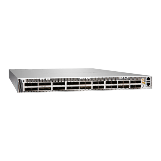
100-Gigabit and 400-Gigabit Ethernet (GbE) ports in a low-profile 1-U form factor. With 9.6 Tbps of throughput, the PTX10001-36MR is optimally designed for peering, core routing, and infrastructure edge routing roles in cloud provider, service provider and content provider networks. -
Page 12: Benefits Of The Ptx10001-36Mr
Benefits of the PTX10001-36MR • Scalability—The PTX10001-36MR scales to 9.6 Tbps in a single chassis, supporting up to 120 10GbE interfaces, 30 40GbE, 96 100GbE interfaces (at line-rate), or 108 100GbE interfaces (oversubscribed), and 24 400GbE interfaces, giving cloud and service providers the performance and scalability needed as networks grow. -
Page 13: Ptx10001-36Mr System Software
PTX10001-36MR System Software The PTX10001-36MR runs Junos OS Evolved, which provides Layer 2 and Layer 3 switching, routing, and security services. Junos OS Evolved runs natively on Linux, giving it direct access to all the Linux utilities and operations. It is designed to be modular, allowing for upgrades to be done on a component- by-component basis without a system reboot. -
Page 14: Cooling And Power
10-Gbps, 25-Gbps, 40-Gbps, and 100-Gbps. Cooling and Power The cooling system in a PTX10001-36MR consists of six fan modules as well as fans housed in the power supplies. Each fan module has dual counter-rotating fans. These fan modules can be hot-swapped and hot-inserted, meaning that you do not need to power off the router or disrupt the routing function to replace a module. -
Page 15: Ptx10001-36Mr Field-Replaceable Units
JNP-3000W-AC-AFO AC AFO 3000W PSU JNP-3000W-DC-AFO DC AFO 3000W PSU NOTE: If you have a Juniper Care service contract, register any addition, change, or upgrade of hardware components at https:/ /www.juniper.net/customers/support/tools/updateinstallbase/. Failure to do so can result in significant delays if you need replacement parts. This note does not apply if you replace existing components with the same type of component. -
Page 16: Ptx10001-36Mr Port Panel
CAUTION: Do not connect feed A and feed B to the same power supply input terminal. • Cooling system—The PTX10001-36MR has six fan modules and within each fan module there are two counter-rotating fans. If a fan module fails and the remaining fan modules are unable to keep the PTX10001-36MR within the desired temperature thresholds, chassis alarms occur and the PTX10001-36MR can shut down. - Page 17 How to Configure the QSFP28 Ports for 10-Gbps, 25-Gbps, and 40-Gbps Speeds | 12 Operating in a fixed core router configuration, the PTX10001-36MR features flexible interface configuration options. The port panel has 24 double density quad small-form factor pluggable (QSFP56-...
- Page 18 • QSFP56-DD transceivers • QSFP28-DD transceivers • QSFP28 transceivers • QSFP+ transceivers • Active optical cables (AOC) • Direct attach copper (DAC) cables • Direct attach copper break out (DACBO) cables • QSA adapters NOTE: Installing either the QDD-400G-LR8 or the QDD-400G-FR4 transceivers next to each other in ports 1, 3, 9, or 11 (on each logical PIC) is supported up to a maximum operating temperature of 35°C at an altitude of up to 6000 feet above sea level.
- Page 19 • The QDD-400G-ZR transceiver can be installed in the top 12 QSFP56-DD ports and 10 bottom QSFP56-DD ports. • The QDD-400G-ZR-M transceiver can be installed in the top 12 QSFP56-DD ports and 6 bottom (in separate 1x2 cages) QSFP56-DD ports. •...
- Page 20 QSFP28 Network Ports The PTX10001-36MR has 12 quad small-form factor pluggable (QSFP28) sockets that are configured as 100GbE ports by default. The QSFP28 network ports support: • QSFP28 transceivers • QSFP+ transceivers • Active optical cables (AOC) • Direct attach copper (DAC) cables •...
- Page 21 The network port is reset to the default Ethernet interface. Port Numbering The interfaces for the PTX10001-36MR are divided into logical PICs and physical optical ports as follows: • PICs: There are three logical PICs, numbered 0, 1, and 2 from left to right.
-
Page 22: Ptx10001-36Mr Network Port Leds
PTX10001-36MR Network Port LEDs Each PTX10001-36MR network port uses a single bicolored LED to indicate link status, activity on the link, or a fault condition. The LEDs for the QSFP28 ports are located above the ports. The LEDs for the QSFP56-DD ports are located to the left of the ports. - Page 23 Figure 5: Network Port LEDs on a PTX10001-36MR 12 network ports—QSFP28 cages 24 network ports—QSFP56-DD cages — — The number next to the LED indicates the port number that the LED belongs to. All 36 network port LEDs behave the same.
-
Page 24: Ptx10001-36Mr Management Panel
You manage the PTX10001-36MR by using the Junos OS Evolved CLI, which is accessible through the console and out-of-band management ports on the management panel. In addition, the management... -
Page 25: Ptx10001-36Mr Management Panel Leds
SSD status LEDs, external clock synchronization ports, and a USB port to support software installation and recovery. Figure 6: PTX10001-36MR Port and Management Panel ESD grounding point RJ-45 console and time of day (TOD) port — — 12 network ports—QSFP28 cages Offline button. - Page 26 The following sections explain how to interpret these LEDs. PTX10001-36MR SSD Port LEDs The PTX10001-36MR has two 200-GB Serial Advanced Technology Attachment (SATA) solid-state drives (SSD). Each SSD has its own status LED. The LEDs are located on the management panel next to the chassis status LEDs.
- Page 27 PTX10001-36MR Chassis Status LEDs The PTX10001-36MR has three LEDs that indicate system status. They are located in the middle of the management panel (see Figure 7 on page 17). Table 7 on page 18 describes the chassis status LEDs on a PTX10001-36MR, their colors and states, and the status that they indicate.
- Page 28 A fault has occurred on the device. PTX10001-36MR Management Port LEDs There is one management port on the PTX10001-36MR that has LEDs that indicate link status and link activity. The port is located on the management panel above the USB port and is labeled MGMT. The...
- Page 29 Status LED (RJ-45) Link activity LED (RJ-45) — — Table 8 on page 20 describes the RJ-45 management port LEDs. Table 8: PTX10001-36MR RJ-45 Management Port LEDs Color State Description Status Unlit No link is established or the port speed is 10 Mbps.
-
Page 30: Ptx10001-36Mr Cooling System
Airflow Through the Chassis | 23 Fan Modules The cooling system in a PTX10001-36MR device consists of fan modules and a single fan in each power supply. There are six fan modules in the PTX10001-36MR. The airflow direction on the PTX10001-36MR is airflow out;... - Page 31 — — Figure 10 on page 22 shows the fan module for the PTX10001-36MR. Figure 10: PTX10001-36MR Fan Module You remove and replace a fan module from the back end of the chassis. During replacement, the device continues to operate for four minutes if one fan module is removed. If two fans are removed, the chassis will shut down immediately.
- Page 32 AIR OUT labels. Airflow Through the Chassis In the PTX10001-36MR cooling system, cool air enters through the vents in the port panel and hot air airflow out or port-to-FRU airflow. exhausts through the FRU panel. This type of airflow is known as hot aisle .
-
Page 33: Ptx10001-36Mr Fan Module Leds
LED on the fan module. Figure 12: Fan Module LEDs Fan LED — Table 10 on page 24 describes the function of the fan module LED. Table 10: PTX10001-36MR Fan Module LED LED Color LED State Description Green On steadily The fan module is operating normally. -
Page 34: Ptx10001-36Mr Power System
The PTX10001-36MR is powered by 3000-W redundant AC/HDVC or DC power supplies that are preinstalled at the factory. The PTX10001-36MR is powered by two power supplies for 1 + 1 redundancy. The power supplies are hot-removable and hot-insertable. If one power supply fails, you can replace it without powering off or disrupting the routing function. -
Page 35: Ptx10001-36Mr Ac/Hvdc Power Supply Description
Each 3000-W AC/HVDC power supply module has a single AC or HVDC input and provides 12 V of power to the system. Figure 13 on page 26 shows the location of the power supplies on the back panel. Figure 13: PTX10001-36MR Back Panel (AC/HVDC Power Supplies Installed) Fan modules (6) Power supplies (2) —... - Page 36 Figure 14 on page 27 shows an example of the AC/HVDC power supply module components. Figure 14: PTX10001-36MR AC/HVDC Power Supply Plug power connector Ejector lever — — Status LED Orange handle — — CAUTION: To avoid electrical injury, carefully follow instructions in "Connect the...
- Page 37 PTX10001-36MR AC Power Supply LED Each PTX10001-36MR AC/HVDC power supply module has a status LED on the power supply module faceplate. Refer to Figure 15 on page Figure 15: PTX10001-36MR AC/HVDC Power Supply Status LED Location Power supply LED —...
- Page 38 (Continued) Table 11: PTX10001-36MR AC/HVDC Power Supply Status LED Description LED Color LED State Description Amber On steadily • The power supply module shut down due to a critical event. Possible causes: high temperature, high power, high current, or fan failure.
- Page 39 1023 W Total system capacity: 6000 W (maximum 6000 W) PTX10001-36MR AC/HVDC Power Specifications The PTX10001-36MR operates within the AC/HVDC input voltage range listed in Table 12 on page 30. The PTX10001-36MR power consumption is listed in Table 13 on page...
- Page 40 210-52 and Canadian Electrical Code (CEC) Section 4-010(3). The cords that can be ordered for the PTX10001-36MR are in compliance. Table 14 on page 31 lists AC power cord specifications provided for each country or region. Table 14: PTX10001-36MR Power Cord Specifications Locale Cord Set Rating Plug Standards...
- Page 41 (Continued) Table 14: PTX10001-36MR Power Cord Specifications Locale Cord Set Rating Plug Standards Spare Juniper Model Graphic Number China, Japan, and 16 A, 250 VAC C20 to Anderson CBL-JNP-SG4-C20- Europe 3-5958p4 Europe (except Italy, 20 A, 250 VAC CEE 7/7 STRAIGHT...
- Page 42 (Continued) Table 14: PTX10001-36MR Power Cord Specifications Locale Cord Set Rating Plug Standards Spare Juniper Model Graphic Number North America 20 A, 250 VAC C20 to Anderson CBL-JNP-SG4-C20 3-5958p4 North America 16 A, 250 VAC Locking NEMA CBL-JNP-SG4-US-L L6-20P North America...
- Page 43 Table 15: PTX10001-36MR Default Power Cords Supplied Locale Spare Juniper Model Number Graphic Australia, Cook Islands, Fiji, Kiribati, CBL-JNP-SG4-AU Nauru, New Zealand, Papua New Guinea, Samoa, Tonga, and Vanuatu Brazil CBL-JNP-SG4-BR China CBL-JNP-SG4-CH...
- Page 44 (Continued) Table 15: PTX10001-36MR Default Power Cords Supplied Locale Spare Juniper Model Number Graphic Afghanistan, Albania, Algeria, CBL-JNP-SG4-EU Andorra, Angola, Argentina, Armenia, Austria, Azerbaijan, Bangladesh, Belarus, Belgium, Benin, Bhutan, Bolivia, Bosnia and Herzegovina, Bulgaria, Burundi, Burkina Faso, Cambodia, Cameroon, Cape Verde, Central African...
- Page 45 (Continued) Table 15: PTX10001-36MR Default Power Cords Supplied Locale Spare Juniper Model Number Graphic Israel CBL-JNP-SG4-IL Chile, Italy, and San Marino CBL-JNP-SG4-IT South Africa CBL-JNP-SG4-SA Maldives and United Kingdom CBL-JNP-SG4-UK...
- Page 46 Panama, Peru, Philippines, Puerto Rico, Saudi Arabia, Taiwan, Thailand, Trinidad and Tobago, U.S. Virgin Islands, United States, and Venezuela Table 16: PTX10001-36MR HVDC Cable Specifications (Bare Wire) Locale Cord Set Rating Spare Juniper Model Number HVDC power cord 16 A, 400 VAC CBL-PWR2-BARE NOTE: The insulation for the wires in the HVDC cables is color coded.
-
Page 47: Ptx10001-36Mr Dc Power Supply Description
PTX10001-36MR DC Power Lugs | 43 View Power Statistics | 44 The PTX10001-36MR DC power supplies are hot-removable and hot-insertable FRUs. Each 3000-W power supply module has a single DC input and provides 12-VDC output with a standby voltage of 12- VDC. -
Page 48: Ptx10001-36Mr Dc Power Supply Led
CAUTION: To avoid electrical injury, carefully follow instructions in "Connect the PTX10001-36MR to Power" on page PTX10001-36MR DC Power Supply LED Each PTX10001-36MR DC power supply module has a status LED on the power supply module faceplate (see Figure 17 on page 39). -
Page 49: Ptx10001-36Mr Dc Input Current Selector (Dip Switch)
PTX10001-36MR DC Input Current Selector (DIP Switch) The PTX10001-36MR DC power supply module can operate with an input current of 80 A or 60 A. You select the input rating by moving the DC input current selector (DIP switch) to the desired setting. Refer Figure 16 on page 38 for the location of the DIP switch. -
Page 50: Ptx10001-36Mr Input Dc Voltage Specification
40 VDC through 72 VDC. PTX10001-36MR Input DC Voltage Specification The PTX10001-36MR DC power supply modules operate within the DC input voltage range listed in Table 18 on page 41. The PTX10001-36MR DC power consumption is listed in... -
Page 51: 60-A Input Feed Power Management
Use the show chassis power detail command to determine the behavior. PTX10001-36MR DC Power Cables You must supply the DC power cables that meet the specifications required by the local code, laws, and standards. -
Page 52: Ptx10001-36Mr Dc Power Lugs
PTX10001-36MR DC Power Lugs The accessory box shipped with the PTX10001-36MR includes the cable lugs that attach to the terminal studs of each power supply module. (The cable lug shown in Figure 18 on page 44... -
Page 53: View Power Statistics
(0.625-in.) center line. Figure 18: DC Power Cable Lugs CAUTION: Before you begin to install the PTX10001-36MR, a licensed electrician must attach a cable lug to the power cables that you supply. A cable with an incorrectly attached lug can damage the PTX10001-36MR. - Page 54 Routing Engine 0 CB 0 System: Zone 0: Capacity: 6000 W (maximum 6000 W) Actual usage: 1230 W Total system capacity: 6000 W (maximum 6000 W) RELATED DOCUMENTATION PTX10001-36MR System Overview | 2 Maintain the PTX10001-36MR Power Supplies | 108...
-
Page 55: Site Planning, Preparation, And Specifications
C HAPTER Site Planning, Preparation, and Specifications PTX10001-36MR Site Preparation Checklist | 47 PTX10001-36MR Site Guidelines and Requirements | 48 PTX10001-36MR Network Cable and Transceiver Planning | 58 PTX10001-36MR Management Cable Specifications and Pinouts | 70... -
Page 56: Ptx10001-36Mr Site Preparation Checklist
PTX10001-36MR Site Preparation Checklist The checklist in Table 21 on page 47 summarizes the tasks you need to perform when preparing a site for a PTX10001-36MR installation. Table 21: Site Preparation Checklist Item or Task For More Information Performed by... -
Page 57: Ptx10001-36Mr Site Guidelines And Requirements
Chassis and Component Lifting Guidelines | 154 Restricted Access Warning | 154 Ramp Warning | 156 Rack-Mounting and Cabinet-Mounting Warnings | 156 Grounded Equipment Warning | 160 PTX10001-36MR Site Guidelines and Requirements IN THIS SECTION PTX10001-36MR Environmental Requirements and Specifications | 49... -
Page 58: Ptx10001-36Mr Environmental Requirements And Specifications
PTX10001-36MR Rack Requirements | 54 PTX10001-36MR Cabinet Requirements | 56 PTX10001-36MR Environmental Requirements and Specifications The PTX10001-36MR must be installed in a rack or cabinet. It must be housed in a dry, clean, well- ventilated, and temperature-controlled environment. Follow these environmental guidelines: •... -
Page 59: General Site Guidelines
Designed to comply with Zone 4 earthquake requirements per NEBS GR-63-CORE, Issue 3. NOTE: Install the PTX10001-36MR only in restricted areas, such as dedicated equipment rooms and equipment closets, in accordance with Articles 110-16, 110-17, and 110-18 of the National Electrical Code, ANSI/NFPA 70. -
Page 60: Ptx10001-36Mr Chassis Grounding Cable And Lug Specifications
• The grounding lug required is a Panduit LCD6-14AH-L or equivalent (not provided). • The grounding cable that you provide for a PTX10001-36MR must be the same size or heavier than the input wire of each power supply. Minimum recommendations are 8 AWG (8.4 mm²) stranded... -
Page 61: Ptx10001-36Mr Clearance Requirements For Airflow And Hardware Maintenance
• You must leave at least 24 in. (61 cm) both in front of and behind the PTX10001-36MR for service personnel to remove and install hardware components. You must leave adequate space at the front and back of the PTX10001-36MR. -
Page 62: Site Electrical Wiring Guidelines
Table 23: Physical Specifications for the PTX10001-36MR Product SKU Weight Height Width Depth PTX10001-36MR With all power supplies and 1.72 in. (4.3 cm) 17.36 in. 25.89 in. fans installed: 39.7 lb (44.09 cm) (65.76 cm) (18.0 kg) Site Electrical Wiring Guidelines... -
Page 63: Ptx10001-36Mr Rack Requirements
• Electrical hazards as a result of power surges conducted over the lines into the equipment. PTX10001-36MR Rack Requirements The PTX10001-36MR chassis is designed to be installed in two-post or four-post racks. Rack requirements consist of: • Rack type • Mounting bracket hole spacing •... - Page 64 Mounting bracket The holes in the mounting brackets are spaced at 1-U (1.75 in. or 4.45 cm) increments, so hole spacing that the PTX10001-36MR can be mounted in any rack that provides holes spaced at that distance. Rack size and •...
-
Page 65: Ptx10001-36Mr Cabinet Requirements
Secure the rack to the ceiling brackets as well as wall or floor brackets for maximum stability. PTX10001-36MR Cabinet Requirements You can mount the PTX10001-36MR in an enclosure or cabinet that contains a four-post 19-in. open rack as defined in Cabinets, Racks, Panels, and Associated Equipment (document number EIA-310-D) published by the Electronics Industry Association. - Page 66 • The PTX10001-36MR fans exhaust hot air through the vents on the fans and power supplies. Install the device in the cabinet in a way that maximizes the open space on the FRU side of the chassis. This maximizes the clearance for critical airflow.
-
Page 67: Ptx10001-36Mr Network Cable And Transceiver Planning
Calculating Power Budget and Power Margin for Fiber-Optic Cables | 68 Determine Transceiver Support for the PTX10001-36MR The PTX10001-36MR has 36 network ports. The 12 QSFP28 network ports on the port panel support QSFP+ and QSFP28 transceivers, direct-attach copper (DAC) cables, active optical cables (AOC) , and DAC breakout cables (DACBO). -
Page 68: Cable And Connector Specifications For Mx And Ptx Series Devices
Juniper Networks. If you face a problem running a Juniper device that uses third-party optical modules or cables, JTAC may help you diagnose host-related issues if the observed issue is not, in the opinion of JTAC, related to the use of the third-party optical modules or cables. - Page 69 12-Fiber MPO Connectors There are two types of cables used with 12-fiber MPO connectors on Juniper Networks devices—patch cables with MPO connectors on both ends, and breakout cables with an MPO connector on one end and four LC duplex connectors on the opposite end. Depending on the application, the cables might use single-mode fiber (SMF) or multimode fiber (MMF).
- Page 70 (Continued) Table 27: Cable Signals for 12-Fiber Ribbon Patch Cables Fiber Signal Unused Unused Unused Unused Rx3 (Receive) Rx2 (Receive) Rx1 (Receive) Rx0 (Receive) Table 28: Cable Pinouts for 12-Fiber Ribbon Patch Cables MPO Pin MPO Pin...
- Page 71 (Continued) Table 28: Cable Pinouts for 12-Fiber Ribbon Patch Cables MPO Pin MPO Pin 12-Fiber Ribbon Breakout Cables with MPO-to-LC Duplex Connectors You can use 12-ribbon breakout cables with MPO-to-LC duplex connectors to connect a QSFP+ transceiver to four separate SFP+ transceivers—for example, 4x10GBASE-LR-to-10GBASE-LR or 4x10GBASE-SR-to-10GBASE-SR SFP+ transceivers.
- Page 72 Rx on LC Duplex 1 12-Ribbon Patch and Breakout Cables Available from Juniper Networks Juniper Networks sells 12-ribbon patch and breakout cables with MPO connectors that meet the requirements described above. It is not required to purchase cables from Juniper Networks.
- Page 73 Table 30: 12-Ribbon Patch and Breakout Cables Available from Juniper Networks Cable Type Connector Type Fiber Type Cable Length Juniper Model Number 12-ribbon patch Socket MPO/PC to socket MPO/PC, MTP12-FF-M1M key up to key up (OM3) MTP12-FF-M3M MTP12-FF-M5M 10 m...
- Page 74 (Continued) Table 30: 12-Ribbon Patch and Breakout Cables Available from Juniper Networks Cable Type Connector Type Fiber Type Cable Length Juniper Model Number 10 m MTP-4LC-S10M 24-Fiber MPO Connectors You can use patch cables with 24-fiber MPO connectors to connect two supported transceivers of the same type—for example, 100GBASE-SR10-to-100GBASE-SR10.
-
Page 75: Fiber-Optic Cable Signal Loss, Attenuation, And Dispersion
The optical interface must meet the requirement FT-1435-CORE in Generic Requirements for Multi- Fiber Optical Connectors . The module must pass the wiggle test defined by IEC 62150-3. LC Duplex Connectors You can use patch cables with LC duplex connectors to connect two supported transceivers of the same type—for example, 40GBASE-LR4-to-40GBASE-LR4 or 100GBASE-LR4-to100GBASE-LR4. - Page 76 Signal Loss in Multimode and Single-Mode Fiber-Optic Cable Multimode fiber is large enough in diameter to allow rays of light to reflect internally (bounce off the walls of the fiber). Interfaces with multimode optics typically use LEDs as light sources. However, LEDs are not coherent sources.
-
Page 77: Calculating Power Budget And Power Margin For Fiber-Optic Cables
TIP: You can use the Hardware Compatibility Tool to find information about the pluggable transceivers supported on your Juniper Networks device. To calculate the power budget and power margin, perform the following tasks: How to Calculate Power Budget for Fiber-Optic Cables To ensure that fiber-optic connections have sufficient power for correct operation, you need to calculate the link's power budget, which is the maximum amount of power it can transmit. -
Page 78: How To Calculate Power Margin For Fiber-Optic Cables
How to Calculate Power Margin for Fiber-Optic Cables After calculating a link's power budget, you can calculate the power margin (P ), which represents the amount of power available after subtracting attenuation or link loss (LL) from the power budget (P ). -
Page 79: Ptx10001-36Mr Management Cable Specifications And Pinouts
PTX10001-36MR Management Cable Specifications and Pinouts IN THIS SECTION Cable Specifications for Console and Management Connections for the PTX10001-36MR | 71 Management Port Connector Pinouts for the PTX10001-36MR | 71 Console and ToD Port Connector Pinouts for the PTX10001-36MR | 72... -
Page 80: Cable Specifications For Console And Management Connections For The Ptx10001-36Mr
Cable Specifications for Console and Management Connections for the PTX10001-36MR Table 32 on page 71 lists the specifications for the cables that connect the PTX10001-36MR to a management device. NOTE: All RJ-45 connectors must conform to the rules and regulations as described in the FCC specification 47 CFR Part 68. -
Page 81: Console And Tod Port Connector Pinouts For The Ptx10001-36Mr
RJ-45 to DB-9 adapter are supplied with the PTX10001-36MR. NOTE: If your laptop or PC does not have a DB-9 plug connector pin and you want to connect your laptop or PC directly to a PTX10001-36MR, use a combination of the RJ-45 cable and... -
Page 82: Usb Port Specifications The Ptx10001-36Mr
Time of Day (ToD) for Precision Time Protocol (PTP) applications. You can use DTR pins as a ToD universal asynchronous receiver/transmitter (UART) by using breakout cables. RTS Output Request to send USB Port Specifications the PTX10001-36MR USB flash drives used with the PTX10001-36MR must support USB 2.0 or later. - Page 83 CAUTION: Remove the USB flash drive before upgrading Junos OS Evolved or rebooting a PTX10001-36MR. Failure to do so could expose your router to unpredictable behavior. RELATED DOCUMENTATION PTX10001-36MR Management Panel | 15...
-
Page 84: Initial Installation And Configuration
Unpack and Mount the PTX10001-36MR | 78 Connect the PTX10001-36MR to Power | 85 Connect the PTX10001-36MR to External Devices | 95 Register Products—Mandatory to Validate SLAs | 97 Perform the Initial Software Configuration for the PTX10001-36MR | 98 Power Off the PTX10001-36MR | 100... -
Page 85: Ptx10001-36Mr Installation Overview
Overview of Installing the PTX10001-36MR | 76 PTX10001-36MR Installation Safety Guidelines | 77 Overview of Installing the PTX10001-36MR Before you begin to install and connect a PTX10001-36MR, ensure that you have reviewed the information in "PTX10001-36MR Installation Safety Guidelines" on page You can mount a PTX10001-36MR: •... -
Page 86: Ptx10001-36Mr Installation Safety Guidelines
Table 18 on page 41 PTX10001-36MR Chassis Lifting Guidelines The weight of a fully loaded PTX10001-36MR is approximately 39.7 lb (18.0 kg). Observe the following guidelines for lifting and moving a PTX10001-36MR: CAUTION: If you are installing the PTX10001-36MR above 60 in. (152.4 cm) from the floor, remove the power supplies and fan modules before attempting to install the device, or ask someone to assist you during the installation. -
Page 87: Unpack And Mount The Ptx10001-36Mr
The PTX10001-36MR chassis is a rigid sheet-metal structure that houses the hardware components. The PTX10001-36MR is shipped in a cardboard carton, secured with foam packing material. The carton also contains an accessory kit and a pointer card with links to the quick start instructions. - Page 88 • The chassis with six fan modules and two power supplies installed • 4-post rack mount kit—2 side mounting blades and 2 side mounting rails NOTE: If you are installing the PTX10001-36MR on a two-post rack, you must order the 2-post rack mount kit separately.
-
Page 89: Mount The Ptx10001-36Mr In A Rack Or Cabinet
Mount the PTX10001-36MR in a Rack or Cabinet IN THIS SECTION Before You Begin Rack Installation | 80 Mount the PTX10001-36MR on Four Posts in a Rack | 81 Mount the PTX10001-36MR on Two Posts in a Rack | 83 You can mount a PTX10001-36MR: •... -
Page 90: Mount The Ptx10001-36Mr On Four Posts In A Rack
6. Ensure that you have all the parts and tools available to mount the PTX10001-36MR in a rack (see "Mount the PTX10001-36MR on Two Posts in a Rack" on page 83 "Mount the PTX10001-36MR on Four Posts in a Rack" on page 81). - Page 91 Figure 24: Attach the PTX10001-36MR to the Rack 8. Continue to support the PTX10001-36MR while sliding the rear mounting blades into the channel of the side mounting rails and securing the blades to the rack. Use four mounting screws (and cage nuts...
-
Page 92: Mount The Ptx10001-36Mr On Two Posts In A Rack
Figure 25 on page Figure 25: Slide Mounting Blades into Mounting Rail 9. Ensure that the PTX10001-36MR chassis is level by verifying that all the screws on the front of the rack are aligned with the screws at the back of the rack. - Page 93 2. Decide whether to place the front (port) end or the back (FRU) end of the PTX10001-36MR at the front of the rack. Position the PTX10001-36MR in such a manner that the AIR OUT labels on components are next to the hot aisle.
-
Page 94: Connect The Ptx10001-36Mr To Power
8. Ensure that the device is level by verifying that all the screws on one side of the rack are aligned with the screws on the other side of the rack. Figure 28: The PTX10001-36MR Secured in a Two-Post Rack RELATED DOCUMENTATION... -
Page 95: Connect The Ptx10001-36Mr To Ground
NOTE: Mount your device in the rack before attaching the grounding lug to the switch. See "Unpack and Mount the PTX10001-36MR" on page NOTE: You must install the PTX10001-36MR in a restricted-access location and ensure that the chassis is always properly grounded. The PTX10001-36MR has a two-hole protective grounding terminal provided on the chassis. - Page 96 • Screwdriver appropriate for the M6 x 10 mm screws. To connect a grounding cable to the PTX10001-36MR: 1. Attach a grounding cable to earth ground (such as the rack in which the PTX10001-36MR is mounted) and then attach it to the chassis grounding point.
-
Page 97: Connect Ac/Hvdc Power To The Ptx10001-36Mr
Each 3000 W AC/HVDC power supply module has a single AC or HVDC input and provides 12 V of power to the system. The power supply in a PTX10001-36MR is a hot-removable and hot-insertable field-replaceable unit (FRU). After removing the power cord from an individual power supply, you can remove and replace it without powering off the router or disrupting router functions. - Page 98 89). NOTE: The coupler end of the power cord model is APP-400. Figure 31: Connect an AC Power Cord to the PTX10001-36MR 5. If the AC power source outlet has a power switch, set it to the off (O) position.
-
Page 99: Connect Dc Power To The Ptx10001-36Mr
For installations that require a separate grounding conductor to the chassis, use the protective earthing terminal on the PTX10001-36MR chassis to connect to the earth ground (see "Connect the PTX10001-36MR to Ground"... - Page 100 • Power cable or cables appropriate for your geographical location to connect DC power to the PTX10001-36MR. We recommend you use a 4 AWG gauge DC power cable such as a Panduit/ LCDX4-14AH-L. The cable lugs are provided with the power supplies.
- Page 101 Figure 32 on page 92 shows the location of the DC input current selector (sometimes called the DIP switch ). Figure 32: PTX10001-36MR DC Power Supply Ejector lever Handle — — Status LED Terminal block cover — — DC input current selector (DIP switch) —...
- Page 102 Figure 34 on page Figure 34: Connect a Straight DC Power Cable to a DC Power Supply in a PTX10001-36MR Connect the power supply to a 80 A or 60 A power source by securing the power cables to the four terminal studs with hex nuts.
- Page 103 WARNING: Ensure that the power cables do not block access to device components or drape where people could trip over them. Figure 36: Close the Cable Manager Latch RELATED DOCUMENTATION PTX10001-36MR Power System | 25 PTX10001-36MR Chassis Grounding Cable and Lug Specifications | 51...
-
Page 104: Connect The Ptx10001-36Mr To External Devices
"Cable Specifications for Console and Management Connections for the PTX10001-36MR" on page You can monitor and manage the PTX10001-36MR by using a dedicated management channel. The device has one management port—a 10/100/1000BASE-T RJ-45 port for copper connections. You use the management port to connect the device to a network for out-of-band management. -
Page 105: Connect The Ptx10001-36Mr To A Management Console
RJ-45 to DB-9 adapter (provided) and a USB to DB-9 plug adapter (not provided). The PTX10001-36MR has a console port with an RJ-45 connector. Use the console port to connect the device directly to a management console, such as a laptop, or to a console server. -
Page 106: Register Products-Mandatory To Validate Slas
PTX10001-36MR Management Panel | 15 Register Products—Mandatory to Validate SLAs Register all new Juniper Networks hardware products and changes to an existing installed product using the Juniper Networks website to activate your hardware replacement service-level agreements (SLAs). CAUTION: Register product serial numbers on the Juniper Networks website. Update the installation base data if any addition or change to the installation base occurs or if the installation base is moved. -
Page 107: Perform The Initial Software Configuration For The Ptx10001-36Mr
• Stop Bits—1 • DCD State—Disregard You’ll need to perform the initial configuration of the PTX10001-36MR through the console port using the CLI or through zero-touch provisioning (ZTP). To provision the PTX10001-36MR using ZTP, you’ll need access to a Dynamic Host Control Protocol (DHCP) server and a File Transfer Protocol (anonymous FTP), Hypertext Transfer Protocol (HTTP), or Trivial File Transfer Protocol (TFTP) server on which the software image and configuration files are stored. - Page 108 New password: password Retype new password: (Optional) Configure the name of the PTX10001-36MR. If the name includes spaces, enclose the name in quotation marks (“ ”). [edit] host-name root@# set system host-name Configure the default gateway.
-
Page 109: Power Off The Ptx10001-36Mr
[edit] root@# set system services telnet NOTE: When Telnet is enabled, you cannot log in to a PTX10001-36MR through Telnet by using root credentials. Root login is allowed only for SSH access. 11. Commit the configuration to activate it on the device. -
Page 110: Power Off The Ac-Powered Ptx10001-36Mr
Power Off the AC-Powered PTX10001-36MR 1. Connect to the router by using one of the following methods: • Connect a management device to the console (COM/ToD) port on a PTX10001-36MR by following the instructions in "Connect the PTX10001-36MR to a Management Console" on page •... -
Page 111: Power Off The Dc-Powered Ptx10001-36Mr
4. Disconnect power to the PTX10001-36MR. If the AC power source outlet has a power switch, set it to the off (O) position. If the AC power source outlet does not have a power switch, gently pull out the plug end of the power cord connected to the power source outlet. - Page 112 CAUTION: The final output of any version of the request system halt command is the “The operating system has halted.” Although traffic and the operating system have stopped, the PTX10001-36MR power supply LEDs remain lit and a fan module continues to run. Wait at least 60 seconds after first seeing this message before following continuing with this procedure.
-
Page 113: Remove, Install, And Maintain Components
C HAPTER Remove, Install, and Maintain Components Maintain the PTX10001-36MR Fan Modules | 105 Maintain the PTX10001-36MR Power Supplies | 108 Maintain the PTX10001-36MR Transceivers and Fiber-Optic Cables | 114 Uninstall the PTX10001-36MR | 125... -
Page 114: Maintain The Ptx10001-36Mr Fan Modules
Install a Fan Module in the PTX10001-36MR | 106 Remove a Fan Module from the PTX10001-36MR Before you remove a fan module from a PTX10001-36MR, ensure that you have taken the necessary precautions to prevent electrostatic discharge (ESD) damage (see "Prevention of Electrostatic Discharge... -
Page 115: Install A Fan Module In The Ptx10001-36Mr
Install a Fan Module in the PTX10001-36MR Before you install a fan module in a PTX10001-36MR, ensure that you have taken the necessary precautions to prevent electrostatic discharge (ESD) damage (see "Prevention of Electrostatic Discharge... - Page 116 2. Taking care not to touch the connectors, remove the fan module from its bag. 3. Align the module with the open slot on the FRU end of the PTX10001-36MR and slide it in until it is fully seated.
-
Page 117: Maintain The Ptx10001-36Mr Power Supplies
Install the DC Power Supply in the PTX10001-36MR | 113 The power supplies in a PTX10001-36MR are hot-removable and hot-insertable field-replaceable units; You can remove and replace them without powering off the PTX10001-36MR or disrupting routing functions. CAUTION: Do not mix AC/HVDC and DC power supplies in the same chassis. - Page 118 ESD point on the device. 3. Disconnect power to the PTX10001-36MR power supply you are going to replace. If the AC input power source outlet has a power switch, set it to the off (O) position. If the AC input power source outlet does not have a power switch, gently pull out the plug end of the power cord connected to the power source outlet.
-
Page 119: Install The Ac/Hvdc Power Supply In The Ptx10001-36Mr
7. Place the power supply in the antistatic bag or on the antistatic mat placed on a flat, stable surface. 8. Install a new power supply within two minutes of removing the old one. Install the AC/HVDC Power Supply in the PTX10001-36MR CAUTION: Install the power supply within two minute of removal to prevent chassis overheating. -
Page 120: Remove The Dc Power Supply From The Ptx10001-36Mr
4. Using both hands, place the power supply in the power supply slot on the field replaceable units (FRU) panel of the PTX10001-36MR and slide it in until it is fully seated and the ejector lever slides into place. See Figure 44 on page 111. - Page 121 Labels on the power supply handle indicate the direction of airflow. See "PTX10001-36MR Cooling System" on page CAUTION: Before you replace a power supply in a PTX10001-36MR, ensure that you have taken the necessary precautions to prevent electrostatic discharge (ESD) damage (see "Prevention of Electrostatic Discharge Damage"...
-
Page 122: Install The Dc Power Supply In The Ptx10001-36Mr
6. Using both hands, place the power supply in the power supply slot on the field replaceable units (FRU) panel of the PTX10001-36MR and slide it in until it is fully seated and the locking lever slides into place. See Figure 46 on page 113. -
Page 123: Maintain The Ptx10001-36Mr Transceivers And Fiber-Optic Cables
NOTE: Each power supply must be connected to a dedicated power source outlet. NOTE: If you have a Juniper Care service contract, register any addition, change, or upgrade of hardware components at https:/ /www.juniper.net/customers/support/tools/updateinstallbase/ Failure to do so can result in significant delays if you need replacement parts. This note does not apply if you replace existing components with the same type of component. -
Page 124: Remove A Qsfp28 Or Qsfp56-Dd Transceiver
To understand how to install or remove a transceiver of a PTX10001-36MR router, read the following sections. Remove a QSFP28 or QSFP56-DD Transceiver 28-Gbps quad small form-factor pluggable (QSFP28) transceivers and double density quad small-form factor pluggable (QSFP56-DD) transceivers can be removed from the device. Transceivers are hot- insertable and hot-removable. -
Page 125: Install A Qsfp28 Or Qsfp56-Dd Transceiver
CAUTION: Do not leave a fiber-optic transceiver uncovered except when inserting or removing cable. The safety cap keeps the port clean and prevents accidental exposure to laser light. 5. Arrange the cable in the cable management system to prevent it from dislodging or developing stress points. -
Page 126: Remove A Transceiver
CAUTION: Do not leave a fiber-optic transceiver uncovered except when inserting or removing cable. The safety cap keeps the port clean and prevents accidental exposure to laser light. 6. Arrange the cable in the cable management system to prevent the cable from dislodging or developing stress points. - Page 127 4. Remove the cable connected to the transceiver (see "Disconnect a Fiber-Optic Cable from the PTX10001-36MR" on page 122). Cover the transceiver and the end of each fiber-optic cable connector with a rubber safety cap immediately after disconnecting the fiber-optic cables.
-
Page 128: Install A Transceiver
NOTE: After you insert a transceiver or after you change the media-type configuration, wait for 6 seconds for the interface to display operational commands. NOTE: We recommend that you use only optical transceivers and optical connectors purchased from Juniper Networks with your Juniper Networks device. - Page 129 Juniper Networks. If you face a problem running a Juniper device that uses third-party optical modules or cables, JTAC may help you diagnose host-related issues if the observed issue is not, in the opinion of JTAC, related to the use of the third-party optical modules or cables.
- Page 130 CAUTION: Before you slide the transceiver into the port, ensure that the transceiver is aligned correctly. Misalignment might cause the pins to bend, making the transceiver unusable. 6. Slide the transceiver in gently until it is fully seated. 7. Remove the rubber safety cap from the transceiver and the end of the cable, and insert the cable into the transceiver.
-
Page 131: Disconnect A Fiber-Optic Cable From The Ptx10001-36Mr
Ejector lever — Disconnect a Fiber-Optic Cable from the PTX10001-36MR Before you disconnect a fiber-optic cable from a PTX10001-36MR, ensure that you have taken the necessary precautions for safe handling of lasers (see "Radiation from Open Port Apertures Warning" on page 164 "Laser and LED Safety Guidelines and Warnings"... -
Page 132: Connect A Fiber-Optic Cable To The Ptx10001-36Mr
4. Cover the fiber-optic cable connector with the rubber safety cap. Connect a Fiber-Optic Cable to the PTX10001-36MR Before you connect a fiber-optic cable to a PTX10001-36MR, ensure that you have taken the necessary precautions for safe handling of lasers (see "Radiation from Open Port Apertures Warning"... -
Page 133: Maintain Fiber-Optic Cables In The Ptx10001-36Mr
Maintain Fiber-Optic Cables in the PTX10001-36MR To maintain fiber-optic cables in a PTX10001-36MR: • When you unplug fiber-optic cables from transceivers, place rubber safety caps over the transceivers and on the end of the cables. -
Page 134: Uninstall The Ptx10001-36Mr
• Two people. One to hold the rack while the other one removes the screws. • Screwdriver appropriate for your rack-mounting screws. If you need to relocate an installed PTX10001-36MR, use the procedure described in this topic. (The remainder of this topic uses “rack” to mean “rack or cabinet.” ) - Page 135 • Ensure that the rack is stable and secured to the building. • Ensure that there is enough space to place the removed PTX10001-36MR in its new location and along the path to the new location.
-
Page 136: Troubleshoot The Hardware
C HAPTER Troubleshoot the Hardware Troubleshoot the PTX10001-36MR | 128... -
Page 137: Troubleshoot The Ptx10001-36Mr
System Alarm Messages on the PTX10001-36MR | 129 PTX10001-36MR Troubleshooting Resources Overview To troubleshoot a PTX10001-36MR, you use the Junos OS Evolved CLI, alarms, and LEDs on the network ports, management panel, and components. • LEDs—When the Routing Engine detects an alarm condition, it lights the red or yellow alarm LED on the management panel as appropriate. -
Page 138: Ptx10001-36Mr Alarm Messages Overview
• JTAC—If you need assistance during troubleshooting, you can contact the Juniper Networks Technical Assistance Center (JTAC) by using the Web or by telephone. If you encounter software problems, or problems with hardware components not discussed here, contact JTAC. PTX10001-36MR Alarm Messages Overview When the Routing Engine detects an alarm condition, it lights the red or yellow alarm LED on the management panel as appropriate. - Page 139 (Continued) Table 35: PTX10001-36MR System Alarm Messages Component Alarm Type CLI Message Recommended Action Fan I2C Failure Check the system log for one of the following messages and report the error message to customer support: • CM ENV Monitor: Get fan speed...
- Page 140 (Continued) Table 35: PTX10001-36MR System Alarm Messages Component Alarm Type CLI Message Recommended Action pem-number is not powered Check the power cord connection and reconnect, if necessary. pem-number is not supported Replace the power supply with a supported power supply.
- Page 141 (Continued) Table 35: PTX10001-36MR System Alarm Messages Component Alarm Type CLI Message Recommended Action sensor-location Temp Sensor Too Hot Check environmental conditions and alarms on other devices. Ensure that environmental factors (such as hot air blowing around the equipment) do not affect the temperature sensor.
- Page 142 (Continued) Table 35: PTX10001-36MR System Alarm Messages Component Alarm Type CLI Message Recommended Action Management Major (red) Management Ethernet 1 Link Down Check whether a cable is connected Ethernet to the management Ethernet interface interface, or whether the cable is defective.
-
Page 143: Contact Customer Support And Return The Chassis Or Components
C HAPTER Contact Customer Support and Return the Chassis or Components Contact Customer Support | 135 Return the PTX10001-36MR Chassis or Components | 136... -
Page 144: Contact Customer Support
Contact Customer Support You can contact Juniper Networks Technical Assistance Center (JTAC) 24 hours a day, 7 days a week in one of the following ways: • On the Web, using the Service Request Manager link at: https:/ /support.juniper.net/support/ • By telephone: •... -
Page 145: Return The Ptx10001-36Mr Chassis Or Components
Return Material Authorization" on page 142. If the PTX10001-36MR is operational and you can access the command-line interface (CLI), you can list serial numbers for the router and some components with a CLI command. If you do not have access to the CLI or if the serial number for the FRU does not appear in the command output, you can locate the serial number ID label on the router or FRU. -
Page 146: List The Chassis And Component Details By Using The Cli
0 and counts from left to right. List the Chassis and Component Details by Using the CLI To list the PTX10001-36MR and components and their serial numbers, use the show chassis hardware CLI operational mode command. user@host> show chassis hardware... -
Page 147: Locate The Ptx10001-36Mr Chassis Serial Number Id Label
JNP10001 Fan Tray, Front to Back Airflow - AFO Locate the PTX10001-36MR Chassis Serial Number ID Label The serial number ID label is located on a label on the top cover. Locate the Serial Number ID Labels on FRU Components For each FRU, you must remove the FRU from the chassis to see the FRU’s serial number ID label. - Page 148 • Fan module—The serial number ID label is on the top of the fan module. See Figure 52 on page 140. Figure 50: Locate the PTX10001-36MR AC Power Supply Serial Number Label Figure 51: Locate the PTX10001-36MR DC Power Supply Serial Number Label...
-
Page 149: Remove The Solid-State Drives For Rma
Figure 52: Locate the PTX10001-36MR Fan Module Serial Number Label Remove the Solid-State Drives for RMA The PTX10001-36MR has two solid-state drives (SSDs) that store the software images, system logs, and the configuration files. Before returning a chassis to Juniper Networks as part of a Return Merchandise Authorization (RMA), you have the option of removing the SSDs and disposing them according to your own company’s security procedures. - Page 150 4. Using the number 2 Phillips screwdriver, remove the four flat-head screws that secure the access door on the the device. Retain the screws for later use. Figure 53: Removing Flat-head Screws in the Access Door 5. Remove the screw holding the SSD in place. 6.
-
Page 151: Return A Ptx10001-36Mr Or Component For Repair Or Replacement
Return a PTX10001-36MR or Component for Repair or Replacement If you need to return a PTX10001-36MR or component to Juniper Networks for repair or replacement, follow this procedure: 1. Determine the serial number of the component. For instructions, see "Locate the Serial Number on a PTX10001-36MR Chassis or Component"... -
Page 152: How To Pack A Ptx10001-36Mr Chassis Or Component For Shipping
How to Pack a PTX10001-36MR for Shipping | 144 How to Pack PTX10001-36MR Components for Shipping | 144 If you are returning a PTX10001-36MR chassis or component to Juniper Networks for repair or replacement, pack the item as described in this topic. -
Page 153: How To Pack A Ptx10001-36Mr For Shipping
How to Pack a PTX10001-36MR for Shipping Here’s how to pack a PTX10001-36MR for shipping: Power off the PTX10001-36MR and remove the AC power cords or DC power cables. See "Power Off the PTX10001-36MR" on page 100. - Page 154 2. Ensure that the components are adequately protected with packing materials and packed so that the pieces are prevented from moving around inside the carton. 3. Close the top of the cardboard shipping box and seal it with packing tape. 4.
-
Page 155: Safety And Compliance Information
C HAPTER Safety and Compliance Information General Safety Guidelines and Warnings | 148 Definitions of Safety Warning Levels | 149 Qualified Personnel Warning | 151 Warning Statement for Norway and Sweden | 151 Fire Safety Requirements | 152 Installation Instructions Warning | 153 Chassis and Component Lifting Guidelines | 154 Restricted Access Warning | 154 Ramp Warning | 156... - Page 156 DC Power Grounding Requirements and Warning | 179 DC Power Wiring Sequence Warning | 180 DC Power Wiring Terminations Warning | 181 Multiple Power Supplies Disconnection Warning | 183 TN Power Warning | 184 PTX10001-36MR Agency Approvals and Compliance Statements | 184...
-
Page 157: General Safety Guidelines And Warnings
General Safety Guidelines and Warnings The following guidelines help ensure your safety and protect the device from damage. The list of guidelines might not address all potentially hazardous situations in your working environment, so be alert and exercise good judgment at all times. •... -
Page 158: Definitions Of Safety Warning Levels
• Some parts of the chassis, including AC and DC power supply surfaces, power supply unit handles, SFB card handles, and fan tray handles might become hot. The following label provides the warning for hot surfaces on the chassis: • Always ensure that all modules, power supplies, and cover panels are fully inserted and that the installation screws are fully tightened. - Page 159 dient u zich bewust te zijn van de bij elektrische schakelingen betrokken risico's en dient u op de hoogte te zijn van standaard maatregelen om ongelukken te voorkomen. Varoitus Tämä varoitusmerkki merkitsee vaaraa. Olet tilanteessa, joka voi johtaa ruumiinvammaan. Ennen kuin työskentelet minkään laitteiston parissa, ota selvää sähkökytkentöihin liittyvistä...
-
Page 160: Qualified Personnel Warning
Qualified Personnel Warning WARNING: Only trained and qualified personnel should install or replace the device. Waarschuwing Installatie en reparaties mogen uitsluitend door getraind en bevoegd personeel uitgevoerd worden. Varoitus Ainoastaan koulutettu ja pätevä henkilökunta saa asentaa tai vaihtaa tämän laitteen. Avertissement Tout installation ou remplacement de l'appareil doit être réalisé... -
Page 161: Fire Safety Requirements
In addition, you should establish procedures to protect your equipment in the event of a fire emergency. Juniper Networks products should be installed in an environment suitable for electronic equipment. We recommend that fire suppression equipment be available in the event of a fire in the vicinity of the equipment and that all local fire, safety, and electrical codes and ordinances be observed when you install and operate your equipment. -
Page 162: Installation Instructions Warning
NOTE: To keep warranties effective, do not use a dry chemical fire extinguisher to control a fire at or near a Juniper Networks device. If a dry chemical fire extinguisher is used, the unit is no longer eligible for coverage under a service agreement. -
Page 163: Chassis And Component Lifting Guidelines
Chassis and Component Lifting Guidelines • Before moving the device to a site, ensure that the site meets the power, environmental, and clearance requirements. • Before lifting or moving the device, disconnect all external cables and wires. • As when lifting any heavy object, ensure that most of the weight is borne by your legs rather than your back. - Page 164 Avertissement Cet appareil est à installer dans des zones d'accès réservé. Ces dernières sont des zones auxquelles seul le personnel de service peut accéder en utilisant un outil spécial, un mécanisme de verrouillage et une clé, ou tout autre moyen de sécurité. L'accès aux zones de sécurité...
-
Page 165: Ramp Warning
Ramp Warning WARNING: When installing the device, do not use a ramp inclined at more than 10 degrees. Waarschuwing Gebruik een oprijplaat niet onder een hoek van meer dan 10 graden. Varoitus Älä käytä sellaista kaltevaa pintaa, jonka kaltevuus ylittää 10 astetta. Avertissement Ne pas utiliser une rampe dont l'inclinaison est supérieure à... - Page 166 Les directives ci-dessous sont destinées à assurer la protection du personnel: • Le rack sur lequel est monté le Juniper Networks switch doit être fixé à la structure du bâtiment.
- Page 167 Le seguenti direttive vengono fornite per garantire la sicurezza personale: • Il Juniper Networks switch deve essere installato in un telaio, il quale deve essere fissato alla struttura dell'edificio. • Questa unità deve venire montata sul fondo del supporto, se si tratta dell'unica unità...
- Page 168 Para garantizar su seguridad, proceda según las siguientes instrucciones: • El Juniper Networks switch debe instalarse en un bastidor fijado a la estructura del edificio. • Colocar el equipo en la parte inferior del bastidor, cuando sea la única unidad en el...
-
Page 169: Grounded Equipment Warning
Följande riktlinjer ges för att trygga din säkerhet: • Juniper Networks switch måste installeras i en ställning som är förankrad i byggnadens struktur. • Om denna enhet är den enda enheten på ställningen skall den installeras längst ned på... -
Page 170: Laser And Led Safety Guidelines And Warnings
Class 1 LED Product Warning | 163 Laser Beam Warning | 163 Juniper Networks devices are equipped with laser transmitters, which are considered a Class 1 Laser Product by the U.S. Food and Drug Administration and are evaluated as a Class 1 Laser Product per IEC/EN 60825-1 requirements. - Page 171 General Laser Safety Guidelines When working around ports that support optical transceivers, observe the following safety guidelines to prevent eye injury: • Do not look into unterminated ports or at fibers that connect to unknown sources. • Do not examine unterminated optical ports with optical instruments. •...
- Page 172 Class 1 LED Product Warning LASER WARNING: Class 1 LED product. Waarschuwing Klasse 1 LED-product. Varoitus Luokan 1 valodiodituote. Avertissement Alarme de produit LED Class I. Warnung Class 1 LED-Produktwarnung. Avvertenza Avvertenza prodotto LED di Classe 1. Advarsel LED-produkt i klasse 1. Aviso Produto de classe 1 com LED.
-
Page 173: Radiation From Open Port Apertures Warning
Aviso Não olhe fixamente para o raio, nem olhe para ele directamente com instrumentos ópticos. ¡Atención! No mirar fijamente el haz ni observarlo directamente con instrumentos ópticos. Varning! Rikta inte blicken in mot strålen och titta inte direkt på den genom optiska instrument. -
Page 174: Maintenance And Operational Safety Guidelines And Warnings
EXposição à radiação e não deverá olhar fixamente para orifícios que se encontrarem a descoberto. ¡Atención! Debido a que la apertura del puerto puede emitir radiación invisible cuando no existe un cable de fibra conectado, evite mirar directamente a las aperturas para no exponerse a la radiación. - Page 175 Waarschuwing Er is ontploffingsgevaar als de batterij verkeerd vervangen wordt. Vervang de batterij slechts met hetzelfde of een equivalent type dat door de fabrikant aanbevolen is. Gebruikte batterijen dienen overeenkomstig fabrieksvoorschriften weggeworpen te worden. Varoitus Räjähdyksen vaara, jos akku on vaihdettu väärään akkuun. Käytä vaihtamiseen ainoastaan saman- tai vastaavantyyppistä...
- Page 176 Jewelry Removal Warning WARNING: Before working on equipment that is connected to power lines, remove jewelry, including rings, necklaces, and watches. Metal objects heat up when connected to power and ground and can cause serious burns or can be welded to the terminals. Waarschuwing Alvorens aan apparatuur te werken die met elektrische leidingen is verbonden, sieraden (inclusief ringen, kettingen en horloges) verwijderen.
- Page 177 ¡Atención! Antes de operar sobre equipos conectados a líneas de alimentación, quitarse las joyas (incluidos anillos, collares y relojes). Los objetos de metal se calientan cuando se conectan a la alimentación y a tierra, lo que puede ocasionar quemaduras graves o que los objetos metálicos queden soldados a los bornes.
- Page 178 6 in. (15.2 cm) of clearance around the ventilation openings. Waarschuwing Om te voorkomen dat welke switch van de Juniper Networks router dan ook oververhit raakt, dient u deze niet te bedienen op een plaats waar de maximale aanbevolen omgevingstemperatuur van 40°...
- Page 179 ¡Atención! Para impedir que un encaminador de la serie Juniper Networks switch se recaliente, no lo haga funcionar en un área en la que se supere la temperatura ambiente máxima recomendada de 40° C. Para impedir la restricción de la entrada de aire, deje un espacio mínimo de 15,2 cm alrededor de las aperturas para ventilación.
-
Page 180: General Electrical Safety Guidelines And Warnings
General Electrical Safety Guidelines and Warnings WARNING: Certain ports on the device are designed for use as intrabuilding (within- GR-1089-CORE ) the-building) interfaces only (Type 2 or Type 4 ports as described in and require isolation from the exposed outside plant (OSP) cabling. To comply with NEBS requirements and protect against lightning surges and commercial power must not be metallically connected to interfaces disturbances, the intrabuilding ports... -
Page 181: Action To Take After An Electrical Accident
• Canada—Canadian Electrical Code, Part 1, CSA C22.1. • Suitable for installation in Information Technology Rooms in accordance with Article 645 of the National Electrical Code and NFPA 75. Peut être installé dans des salles de matériel de traitement de l’information conformément à l’article 645 du National Electrical Code et à... -
Page 182: Prevention Of Electrostatic Discharge Damage
Prevention of Electrostatic Discharge Damage Device components that are shipped in antistatic bags are sensitive to damage from static electricity. Some components can be impaired by voltages as low as 30 V. You can easily generate potentially damaging static voltages whenever you handle plastic or foam packing material or if you move components across plastic or carpets. -
Page 183: Ac Power Electrical Safety Guidelines
• When removing or installing a component that is subject to ESD damage, always place it component- side up on an antistatic surface, in an antistatic card rack, or in an antistatic bag (see Figure 55 on page 174). If you are returning a component, place it in an antistatic bag before packing it. Figure 55: Placing a Component into an Antistatic Bag CAUTION: ANSI/TIA/EIA-568 cables such as Category 5e and Category 6 can get electrostatically charged. -
Page 184: Ac Power Disconnection Warning
“ATTENTION: CET APPAREIL COMPORTE PLUS D'UN CORDON D'ALIMENTATION. AFIN DE PRÉVENIR LES CHOCS ÉLECTRIQUES, DÉBRANCHER TOUT CORDON D'ALIMENTATION AVANT DE FAIRE LE DÉPANNAGE.” • AC-powered devices are shipped with a three-wire electrical cord with a grounding-type plug that fits only a grounding-type power outlet. Do not circumvent this safety feature. Equipment grounding must comply with local and national electrical codes. -
Page 185: Dc Power Electrical Safety Guidelines
Avertissement Avant de travailler sur un châssis ou à proximité d'une alimentation électrique, débrancher le cordon d'alimentation des unités en courant alternatif. Warnung Bevor Sie an einem Chassis oder in der Nähe von Netzgeräten arbeiten, ziehen Sie bei Wechselstromeinheiten das Netzkabel ab bzw. Avvertenza Prima di lavorare su un telaio o intorno ad alimentatori, scollegare il cavo di alimentazione sulle unità... -
Page 186: Dc Power Copper Conductors Warning
NOTE: Primary overcurrent protection is provided by the building circuit breaker. This breaker must protect against excess currents, short circuits, and earth grounding faults in accordance with NEC ANSI/NFPA 70. • Ensure that the polarity of the DC input wiring is correct. Under certain conditions, connections with reversed polarity might trip the primary circuit breaker or damage the equipment. -
Page 187: Dc Power Disconnection Warning
DC Power Disconnection Warning WARNING: Before performing any of the DC power procedures, ensure that power is removed from the DC circuit. To ensure that all power is off, locate the circuit breaker on the panel board that services the DC circuit, switch the circuit breaker to the OFF position, and tape the device handle of the circuit breaker in the OFF position. -
Page 188: Dc Power Grounding Requirements And Warning
Aviso Antes de executar um dos seguintes procedimentos, certifique-se que desligou a fonte de alimentação de energia do circuito de corrente contínua. Para se assegurar que toda a corrente foi DESLIGADA, localize o disjuntor no painel que serve o circuito de corrente contínua e coloque-o na posição OFF (Desligado), segurando nessa posição a manivela do interruptor do disjuntor com fita isoladora. -
Page 189: Dc Power Wiring Sequence Warning
Avvertenza In fase di installazione dell'unità, eseguire sempre per primo il collegamento a massa e disconnetterlo per ultimo. Advarsel Når enheten installeres, må jordledningen alltid tilkobles først og frakobles sist. Aviso Ao instalar a unidade, a ligação à terra deverá ser sempre a primeira a ser ligada, e a última a ser desligada. -
Page 190: Dc Power Wiring Terminations Warning
Stromversorgung ist -48V zu -48V, +RTN zu +RTN und dann Erdanschluss zu Erdanschluss. Es ist zu beachten dass der Erdanschluss immer zuerst angeschlossen und als letztes abgetrennt wird. Avvertenza Mostra la morsettiera dell alimentatore CC. Cablare l'alimentatore CC usando i connettori adatti all'estremità del cablaggio, come illustrato. La corretta sequenza di cablaggio è... - Page 191 Waarschuwing Wanneer geslagen bedrading vereist is, dient u bedrading te gebruiken die voorzien is van goedgekeurde aansluitingspunten, zoals het gesloten-lus type of het grijperschop type waarbij de aansluitpunten omhoog wijzen. Deze aansluitpunten dienen de juiste maat voor de draden te hebben en dienen zowel de isolatie als de geleider vast te klemmen.
-
Page 192: Multiple Power Supplies Disconnection Warning
Varning! När flertrådiga ledningar krävs måste godkända ledningskontakter användas, t.ex. kabelsko av sluten eller öppen typ med uppåtvänd tapp. Storleken på dessa kontakter måste vara avpassad till ledningarna och måste kunna hålla både isoleringen och ledaren fastklämda. Multiple Power Supplies Disconnection Warning WARNING: The network device has more than one power supply connection. -
Page 193: Tn Power Warning
PTX10001-36MR Agency Approvals and Compliance Statements IN THIS SECTION PTX10001-36MR Agency Approvals | 185 Compliance Statements for EMC Requirements | 186 Compliance Statements for Environmental Requirements | 189 Compliance Statements for NEBS | 189 PTX10001-36MR Compliance Statements for Acoustic Noise | 189... -
Page 194: Ptx10001-36Mr Agency Approvals
PTX10001-36MR Agency Approvals IN THIS SECTION Compliance Statement for Argentina | 186 The PTX10001-36MR complies with the following standards Electromagnetic Compatibility (EMC) Requirements • FCC 47 CFR Part 15 • ICES-003 / ICES-GEN • EN 300 386 V1.6.1 • EN 300 386 V2.1.1 •... -
Page 195: Compliance Statements For Emc Requirements
• CFR, Title 21, Chapter 1, Subchapter J, Part 1040 • REDR c 1370 OR CAN/CSA-E 60825-1- Part 1 • IEC 60825-1 • IEC 60825-2 The PTX10001-36MR complies with the following standards: • GR-1089-Core • GR-3160-Core Compliance Statement for Argentina EQUIPO DE USO IDÓNEO. - Page 196 Canada CAN ICES-3 (A)/NMB-3(A) European Community This is a Class A product. In a domestic environment, this product might cause radio interference in which case the user might be required to take adequate measures. Israel Translation from Hebrew—Warning: This product is Class A. In residential environments, the product might cause radio interference, and in such a situation, the user might be required to take adequate measures.
- Page 197 Korea The preceding translates as follows: This equipment is Industrial (Class A) electromagnetic wave suitability equipment and seller or user should take notice of it, and this equipment is to be used in the places except for home. Taiwan The preceding translates as follows: This is Class A product.
-
Page 198: Compliance Statements For Environmental Requirements
• The battery return connection is to be treated as an isolated DC return (that is, DC-I), as defined in GR-1089-CORE. NOTE: • PTX10001-36MR meets the NEBS GR-1089 Issue 6 requirements. • You must provision a readily accessible device outside of the equipment to disconnect power. The device must also be rated based on local electrical code practice.
Need help?
Do you have a question about the PTX10001-36MR and is the answer not in the manual?
Questions and answers