Juniper M320 Hardware Manual
Multiservice edge router
Hide thumbs
Also See for M320:
- Hardware manual (392 pages) ,
- Quick start manual (38 pages) ,
- Datasheet (8 pages)

Related Manuals for Juniper M320


Summary of Contents for Juniper M320
- Page 1 All manuals and user guides at all-guides.com M320 Multiservice Edge Router Hardware Guide Published: 2010-10-26 Copyright © 2010, Juniper Networks, Inc.
- Page 2 Products made or sold by Juniper Networks or components thereof might be covered by one or more of the following patents that are owned by or licensed to Juniper Networks: U.S. Patent Nos. 5,473,599, 5,905,725, 5,909,440, 6,192,051, 6,333,650, 6,359,479, 6,406,312, 6,429,706, 6,459,579, 6,493,347, 6,538,518, 6,538,899, 6,552,918, 6,567,902, 6,578,186, and 6,590,785.
- Page 3 The information in this document is current as of the date listed in the revision history. YEAR 2000 NOTICE Juniper Networks hardware and software products are Year 2000 compliant. The Junos OS has no known time-related limitations through the year 2038. However, the NTP application is known to have some difficulty in the year 2036.
- Page 4 Juniper, even if such feature, function, service, application, operation, or capability is enabled without a key; (g) distribute any key for the Software provided by Juniper to any third party; (h) use the...
- Page 5 Customer did not originally purchase from Juniper or an authorized Juniper reseller; (k) disclose the results of testing or benchmarking of the Software to any third party without the prior written consent of Juniper; or (l) use the Software in any manner other than as expressly provided herein.
- Page 6 (or services are accessed by) the Software shall be a third party beneficiary with respect to this Agreement, and such licensor or vendor shall have the right to enforce this Agreement in its own name as if it were Juniper. In addition, certain third party software may be provided with the Software and is subject to the accompanying license(s), if any, of its respective owner(s).
-
Page 7: Table Of Contents
M320 Routing Engine Description ........19... - Page 8 M320 Power System Description ........33...
- Page 9 Reinstalling an M320 Rear Fan Tray ....... . . 82...
- Page 10 Initially Configuring the M320 Router ........103...
- Page 11 Removing an M320 Front Fan Tray ....... . . 153...
- Page 12 M320 Chassis Lifting Guidelines ........216...
- Page 13 M320 Router Physical Specifications ....... 245 M320 Router Physical Specifications ........245 Appendix C M320 Router Environmental Specifications .
- Page 14 Tools and Parts Required to Remove Components From an M320 Router ..282 Packing the M320 Router for Shipment ....... . 283 Packing M320 Router Components for Shipment .
- Page 15 M320 Hardware Components ........
- Page 16 Chapter 9 Providing Power to the M320 Router ....... . 95 Figure 54: Connecting AC Power to the M320 Router .
- Page 17 Appendix A M320 Router Safety and Regulatory Compliance Information ..209 Figure 109: Placing a Component into an Electrostatic Bag ....215 Copyright ©...
- Page 18 M320 Router Hardware Guide Figure 110: M320 Declaration of Conformity ......242 Appendix D M320 Router Power Guidelines, Requirements, and Specifications .
- Page 19 M320 Hardware Components ........5 Table 3: FPCs Supported by the M320 Router ......14 Table 4: SIB LEDs .
- Page 20 M320 Router Physical Specifications ....... 245 Table 25: M320 Physical Specifications ....... . 245 Appendix C M320 Router Environmental Specifications .
-
Page 21: About The Documentation
Objectives This documentation describes hardware components, installation, basic configuration, and basic troubleshooting procedures for the Juniper Networks M320 router. It explains how to prepare your site for router installation, unpack and install the hardware, power on the router, perform initial software configuration, and perform routine maintenance. -
Page 22: Audience
Audience This documentation is designed for network administrators who are installing and maintaining a Juniper Networks router or preparing a site for router installation. To use the documentation, you need a broad understanding of networks in general, the Internet in particular, networking principles, and network configuration. Any detailed discussion of these concepts is beyond the scope of this hardware documentation. -
Page 23: Documentation Feedback
Documentation Feedback We encourage you to provide feedback, comments, and suggestions so that we can improve the documentation. You can send your comments to techpubs-comments@juniper.net , or fill out the documentation feedback form at Copyright © 2010, Juniper Networks, Inc. xxiii... -
Page 24: Requesting Technical Support
7 days a week, 365 days a year. Self-Help Online Tools and Resources For quick and easy problem resolution, Juniper Networks has designed an online self-service portal called the Customer Support Center (CSC) that provides you with the following features: Find CSC offerings: http://www.juniper.net/customers/support/... -
Page 25: Opening A Case With Jtac
You can open a case with JTAC on the Web or by telephone. Use the Case Management tool in the CSC at http://www.juniper.net/cm/ Call 1-888-314-JTAC (1-888-314-5822 toll-free in the USA, Canada, and Mexico). For international or direct-dial options in countries without toll-free numbers, see http://www.juniper.net/support/requesting-support.html Copyright © 2010, Juniper Networks, Inc. - Page 26 All manuals and user guides at all-guides.com M320 Router Hardware Guide xxvi Copyright © 2010, Juniper Networks, Inc.
-
Page 27: Part 1 M320 Multiservice Edge Router Overview
Unpacking the M320 Router on page 49 Installing the M320 Router Mounting Hardware on page 55 Installing the M320 Router Using a Mechanical Lift on page 63 Installing the M320 Router Without a Mechanical Lift on page 71 Connecting the M320 Router on page 89... - Page 28 All manuals and user guides at all-guides.com M320 Router Hardware Guide Copyright © 2010, Juniper Networks, Inc.
-
Page 29: M320 Router Overview
The router can be deployed in core, peering, and data center applications, but is optimized for dense edge aggregation and service creation. The M320 router can provide a single point of edge aggregation for thousands of customers over any access type, including ATM, Frame Relay, Ethernet, and TDM, at any speed from DS0 up to OC192/STM64 and 10-Gigabit Ethernet. - Page 30 All manuals and user guides at all-guides.com M320 Router Hardware Guide M320 Environmental Specifications on page 247 M320 Power Requirements on page 250 Copyright © 2010, Juniper Networks, Inc.
-
Page 31: Chapter 2 M320 Hardware Components
M320 Component Redundancy on page 5 M320 Chassis Description on page 6 M320 Midplane Description on page 9 M320 Flexible PIC Concentrator (FPC) Description on page 11 M320 FPCs Supported on page 14 M320 PIC Description on page 15 M320 Switch Interface Board (SIB) Overview on page 16... -
Page 32: M320 Chassis Description
M320 Router Hardware Guide For information about the effect of taking the host subsystem offline, see “Taking the M320 Host Subsystem Offline” on page 160. For more information about high availability features, see the Junos OS High Availability Configuration Guide. -
Page 33: Chapter 2 M320 Hardware Components
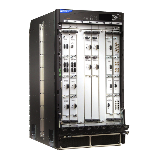
All manuals and user guides at all-guides.com Chapter 2: M320 Hardware Components Figure 1: Front View of a Fully Configured Router Chassis Copyright © 2010, Juniper Networks, Inc. -
Page 34: Figure 2: Rear View Of A Fully Configured Ac-Powered Router Chassis
All manuals and user guides at all-guides.com M320 Router Hardware Guide Figure 2: Rear View of a Fully Configured AC-Powered Router Chassis Copyright © 2010, Juniper Networks, Inc. -
Page 35: M320 Midplane Description
All manuals and user guides at all-guides.com Chapter 2: M320 Hardware Components Figure 3: Rear View of a Fully Configured DC-Powered Router Chassis For chassis serial number information , see “Locating M320 Component Serial Numbers Using the CLI” on page 273. Related... -
Page 36: Figure 4: Midplane
Signal path—The midplane provides the signal path to the FPCs, SIBs, Routing Engines, CB, and other system components for monitoring and control of the system. Figure 4: Midplane For chassis serial number information , see “Locating M320 Component Serial Numbers Using the CLI” on page 273. Copyright © 2010, Juniper Networks, Inc. -
Page 37: M320 Flexible Pic Concentrator (Fpc) Description
Depending on the FPC type, an FPC has either two or four slots into which a PIC can be installed (see “M320 FPCs Supported” on page 14 for more information). An FPC can be installed into any FPC slot on the router, regardless of which PICs it contains. -
Page 38: Figure 5: Fpc Installed In Router Chassis
M320 Router Hardware Guide Figure 5: FPC Installed in Router Chassis The M320 router supports the following types of FPCs (see Figure 6 on page 13 ): FPC1, Enhanced II FPC1, and Enhanced III FPC1—Rated at 4 gigabits per second (Gbps) full duplex FPC2, Enhanced II FPC2, and Enhanced III FPC2—Rated at 16 Gbps full duplex... -
Page 39: Figure 6: Fpc1, Fpc2, And Fpc3 For The M320 Router
Chapter 2: M320 Hardware Components Figure 6: FPC1, FPC2, and FPC3 for the M320 Router Figure 7 on page 13 shows the Enhanced II FPCs that the M320 router supports. Figure 7: Enhanced II FPC1, FPC2, and FPC3 for the M320 Router... -
Page 40: M320 Fpcs Supported
Troubleshooting the M320 FPCs on page 131 M320 FPCs Supported Table 3 on page 14 lists the FPCs that the M320 router supports. You can install any combination of the following FPCs in the M320 router. Table 3: FPCs Supported by the M320 Router... -
Page 41: M320 Pic Description
All manuals and user guides at all-guides.com Chapter 2: M320 Hardware Components Table 3: FPCs Supported by the M320 Router (continued) Maximum Maximum Throughput per FPC First Junos OS Number of PICs FPC Type FPC Name FPC Model Number (Full-Duplex) -
Page 42: M320 Switch Interface Board (Sib) Overview
SIB0 through SIB3 (top to bottom). The M320 router can be configured with two, three, or four SIBs. You can upgrade from two to three SIBs or from three to four SIBs without resetting or stopping Packet Forwarding Engines. Each FPC has a dedicated ASIC with up to four high-speed links that connect to the SIBs (one link per SIB). -
Page 43: M320 Performance For Different Sib Configurations
On steadily SIB has failed. FAIL Related Replacing an M320 SIB on page 172 Documentation Maintaining the M320 SIBs on page 121 M320 Performance for Different SIB Configurations Table 5 on page 17 describes expected performance per total active SIBs for different FPC and PIC configurations. -
Page 44: M320 Host Subsystem Overview
M320 Routing Engine 600 on page 20 M320 Routing Engine 1600 on page 21 M320 Routing Engine 2000 on page 22 M320 Control Board (CB) Description on page 23 M320 Control Board (CB) LEDs on page 25 M320 Host Subsystem Description The host subsystem provides the routing and system management functions of the router. -
Page 45: M320 Routing Engine Description
(including Routing Engine status) are located in the middle of the craft interface rather than the Routing Engine faceplate. For more information about the host subsystem LEDs, see “M320 Craft Interface Host Subsystem LEDs” on page 30. -
Page 46: M320 Routing Engine 600
M320 Routing Engine 1600 on page 21 M320 Routing Engine 2000 on page 22 M320 Routing Engine 600 Each M320 Routing Engine 600 consists of the following components: CPU—Runs Junos OS to maintain the router's routing tables and routing protocols. It has a Pentium-class processor. -
Page 47: M320 Routing Engine 1600
M320 Routing Engine Ports on page 26 Documentation M320 Routing Engine Description on page 19 Replacing an M320 Routing Engine on page 166 M320 Routing Engine 1600 Figure 10: Routing Engine 1600 Each Routing Engine (shown in Figure 10 on page 21) consists of the following components: CPU—Runs Junos OS to maintain the router's routing tables and routing protocols. -
Page 48: M320 Routing Engine 2000
M320 Routing Engine Ports on page 26 Documentation M320 Routing Engine Description on page 19 Replacing an M320 Routing Engine on page 166 M320 Routing Engine 2000 Figure 11: Routing Engine 2000 Each Routing Engine (shown in Figure 11 on page 22 consists of the following components: CPU—Runs Junos OS to maintain the router's routing tables and routing protocols. -
Page 49: M320 Control Board (Cb) Description
M320 Routing Engine Ports on page 26 Documentation M320 Routing Engine Description on page 19 Replacing an M320 Routing Engine on page 166 M320 Control Board (CB) Description Each CB works with an adjacent Routing Engine to provide control and monitoring functions for the router (see Figure 12 on page 24). -
Page 50: Figure 12: Cb
Fast Ethernet switch—Provides a 100-Mbps Ethernet link to each FPC for Routing Engine data transfers. Three LEDs, located on the CB faceplate, indicate the status of the CB. “M320 Control Board (CB) LEDs” on page 25 describes the functions of the CB LEDs. -
Page 51: M320 Control Board (Cb) Leds
M320 Control Board (CB) Description on page 23 Replacing an M320 CB on page 163 M320 Connector Interface Panel (CIP) Overview M320 Connector Interface Panel (CIP) Description on page 25 M320 Routing Engine Ports on page 26 T640 Alarm Relay Contacts on page 27... -
Page 52: M320 Routing Engine Ports
All manuals and user guides at all-guides.com M320 Router Hardware Guide Figure 13: CIP Related M320 Craft Interface Description on page 28 Documentation M320 Alarm Relay Contacts Replacing the M320 CIP on page 140 M320 Routing Engine Ports The CIP has two sets of ports that you use to connect the Routing Engines to external management devices. -
Page 53: T640 Alarm Relay Contacts
M320 Connector Interface Panel (CIP) Description on page 25 Replacing the M320 CIP on page 140 M320 RJ-48 Connector Pinouts for the Control Board External Clock Inputs on page 269 T640 Alarm Relay Contacts The CIP has two alarm relay contacts for connecting the router to external alarm devices. -
Page 54: M320 Craft Interface Description
M320 Router Hardware Guide M320 Craft Interface Power Supply LEDs on page 31 M320 Craft Interface FPC LEDs and Online/Offline Buttons on page 32 M320 Craft Interface Description The craft interface allows you to view status and troubleshooting information at a glance and to perform many system control functions. -
Page 55: M320 Craft Interface Led Display And Navigation Buttons
M320 Craft Interface Description on page 28 Documentation M320 Alarm Relay Contacts M320 Craft Interface LED Display and Navigation Buttons on page 29 M320 Craft Interface LED Display and Navigation Buttons A four-line LED display is located in the craft interface, along with six navigation buttons. -
Page 56: M320 Craft Interface Host Subsystem Leds
The prefix on each line indicates whether the alarm is a red ( ) or yellow ( alarm. For a list of alarm messages that can appear on the LED display, see “M320 Chassis and Interface Alarm Messages” on page 127. Related... -
Page 57: M320 Craft Interface Sib Leds
M320 Host Subsystem Description on page 18 Documentation M320 Craft Interface Description on page 28 M320 Craft Interface Alarm LEDs and ACO/LT Button on page 28 M320 Alarm Relay Contacts M320 Craft Interface SIB LEDs Each SIB has two LEDs on the craft interface that indicate its status. The SIB LEDs, labeled... -
Page 58: M320 Craft Interface Fpc Leds And Online/Offline Buttons
M320 Alarm Relay Contacts M320 AC Power Supply on page 33 M320 DC Power Supply on page 34 M320 Craft Interface FPC LEDs and Online/Offline Buttons Each FPC slot has two LEDs that indicate its status. The FPC LEDs, labeled FPC0... -
Page 59: M320 Power System Overview
M320 Fuse Specifications on page 36 M320 Power System Description The M320 router uses either AC or DC power supplies. The router is configurable with two, three, or four AC power supplies or two or four DC power supplies. The power supplies connect to the midplane, which distributes the different output voltages produced by the power supplies to the router components, depending on their voltage requirements. -
Page 60: M320 Dc Power Supply
“check” state and does not operate even though it has not failed (this is because the router requires two power supplies to operate). For AC power supply and power system electrical specifications, see “M320 AC Power Electrical Specifications” on page 252 and “M320 AC Power Cord Specifications” on page 253. -
Page 61: M320 Power Supply Leds
(see Table 12 on page 35 , which applies to the AC and DC power supply). The power supply status is also reflected in two LEDs on the craft interface (see “M320 Craft Interface Power Supply LEDs” on page 31). In addition, a power supply failure triggers the red alarm LED on the craft interface. -
Page 62: M320 Fuses
PEM0 though it is installed correctly and the power supplies are providing power to the router. For more information, see “Troubleshooting the M320 Fuses” on page 133. For fuse replacement instructions, see “Replacing an M320 Fuse” on page 204. Related... -
Page 63: M320 Cooling System Description
M320 Fuses on page 36 Documentation Site Electrical Wiring Guidelines for M Series, MX Series, and T Series Routers on page 249 Preventing Electrostatic Discharge Damage to an M320 Router on page 214 Troubleshooting the M320 Fuses on page 133 M320 Cooling System Description... -
Page 64: M320 Cable Management System Description
Related M320 Cabinet Airflow Requirements on page 47 Documentation Maintaining the M320 Fan Trays on page 111 Troubleshooting the M320 Cooling System on page 129 M320 Cable Management System Description The cable management system (see Figure 20 on page 39) consists of a row of nine semicircular plastic bobbins mounted on the front of the router below the FPC card cage. -
Page 65: Figure 20: Cable Management System
Included with your router shipment is a clear plastic cable cover that you can attach to slots in the cable guards without using tools. The cable cover prevents the PIC and CIP cables from being disturbed or snagged. Related M320 Chassis Description on page 6 Documentation Copyright © 2010, Juniper Networks, Inc. - Page 66 All manuals and user guides at all-guides.com M320 Router Hardware Guide Copyright © 2010, Juniper Networks, Inc.
-
Page 67: Chapter 3 Preparing The Site For M320 Router Installation
Preparing the Site for M320 Router Installation M320 Site Preparation Checklist Requirements on page 41 Rack Requirements for the M320 Router on page 42 M320 Clearance Requirements on page 44 M320 Cabinet Requirements on page 45 M320 Site Preparation Checklist Requirements The checklist in Table 14 on page 41 summarizes the tasks you need to perform when preparing a site for router installation. -
Page 68: Rack Requirements For The M320 Router
“Maintaining M320 PICs and PIC Cables” on page 119 Related M320 Chassis Lifting Guidelines on page 216 Documentation General Safety Guidelines for M Series, MX Series, and T Series Routers on page 211 Maintenance and Operational Safety Warnings for M Series, MX Series, and T Series... -
Page 69: Chapter 3 Preparing The Site For M320 Router Installation
Cabinets, Racks, Panels, and Associated Equipment (document number EIA-310-D) published by the Electronics Industry Association. You can stack two M320 routers in a rack that has at least 40 U (70 in. or 1.78 m) of usable vertical space. -
Page 70: M320 Clearance Requirements
(see Figure 22 on page 44): For the cooling system to function properly, the airflow around the chassis must be unrestricted. “M320 Cooling System Description” on page 37 depicts the airflow in the router. For service personnel to remove and install hardware components, there must be adequate space at the front and back of the router. -
Page 71: M320 Cabinet Requirements
All manuals and user guides at all-guides.com Chapter 3: Preparing the Site for M320 Router Installation For instructions about installing the mounting hardware, see “Installing the M320 Mounting Hardware for a Four-Post Rack or Cabinet” on page 56. The chassis height of 34.80 in. (88.4 cm) is approximately 20 U. A... -
Page 72: M320 Cabinet Size And Clearance Requirements
All manuals and user guides at all-guides.com M320 Router Hardware Guide M320 Cabinet Size and Clearance Requirements The minimum size enclosed cabinet that can accommodate the router is 600 mm wide and 800 mm deep. A cabinet larger than the minimum requirement provides better airflow and reduces the chance of overheating. -
Page 73: M320 Cabinet Airflow Requirements
If the cabinet contains a top or doors, perforations in these elements assist with removing the hot air exhaust. For an illustration of chassis airflow, see “M320 Cooling System Description” on page 37. -
Page 74: Figure 24: Airflow Baffle Template
All manuals and user guides at all-guides.com M320 Router Hardware Guide Figure 24: Airflow Baffle Template Related Maintaining the M320 Air Filters on page 110 Documentation Maintaining the M320 Fan Trays on page 111 Troubleshooting the M320 Cooling System on page 129... -
Page 75: Chapter 4 Unpacking The M320 Router
56or “Installing the M320 Mounting Hardware for Open-Frame Racks” on page 60. Install the chassis. See “Installing the M320 Router Using a Mechanical Lift” on page 63 or “Installing the M320 Chassis in the Rack Manually” on page 79. -
Page 76: Unpacking The M320 Router
M320 Router Hardware Guide Blank panels to cover any slots not occupied by a component Related M320 Chassis Lifting Guidelines on page 216 Documentation Unpacking the M320 Router The Router is shipped in a wooden crate. A wooden pallet forms the base of the crate. -
Page 77: Verifying The M320 Router Parts Received
Related Verifying the M320 Router Parts Received on page 51 Documentation Installing the M320 Router Using a Mechanical Lift on page 63 Installing the M320 Chassis in the Rack Manually on page 79 Verifying the M320 Router Parts Received A packing list is included in each shipment. Check the parts in the shipment against the items on the packing list. -
Page 78: Table 17: M320 Router Accessory Box Parts List
All manuals and user guides at all-guides.com M320 Router Hardware Guide Table 16: M320 Router Parts List for a Fully Configured Router (continued) Component Quantity FPCs Up to 8 PICs Up to 4 per FPC SIBs Routing Engines 1 or 2... - Page 79 All manuals and user guides at all-guides.com Chapter 4: Unpacking the M320 Router Table 17: M320 Router Accessory Box Parts List (continued) Part Quantity PCMCIA card holder and hook-and-loop fasteners (male 1 of each and female) DC Power and grounding cable lugs...
- Page 80 All manuals and user guides at all-guides.com M320 Router Hardware Guide Copyright © 2010, Juniper Networks, Inc.
-
Page 81: Chapter 5 Installing The M320 Router Mounting Hardware
Verifying the M320 Rack-Mounting Hardware Received on page 55 M320 Mounting Hole Locations for Four-Post Racks or Cabinets on page 56 Installing the M320 Mounting Hardware for a Four-Post Rack or Cabinet on page 56 M320 Mounting Hole Locations for Open-Frame Racks on page 59... -
Page 82: M320 Mounting Hole Locations For Four-Post Racks Or Cabinets
Installing the M320 Mounting Hardware for a Four-Post Rack or Cabinet To prepare to install the M320 router in a four-post rack or cabinet, you install the large shelf and the spacer bars on the front rail, and the small mounting shelf on the rear rail (see Figure 26 on page 57. -
Page 83: Installing Cage Nuts (If Needed) For M320 Four-Post Racks Or Cabinets
Figure 26: Installing the Mounting Hardware for a Four-Post Rack or Cabinet Installing Cage Nuts (If Needed) for M320 Four-Post Racks or Cabinets on page 57 Installing the Large Mounting Shelf for M320 Four-Post Racks or Cabinets on page 58... -
Page 84: Cabinets
All manuals and user guides at all-guides.com M320 Router Hardware Guide Installing the Large Mounting Shelf for M320 Four-Post Racks or Cabinets To install the large mounting shelf: On the front of each front rack rail, partially insert a mounting screw into the lowest hole. -
Page 85: M320 Mounting Hole Locations For Open-Frame Racks
All manuals and user guides at all-guides.com Chapter 5: Installing the M320 Router Mounting Hardware Figure 27: Center-Mounting Bracket Removal Related M320 Site Preparation Checklist Requirements on page 41 Documentation M320 Chassis Lifting Guidelines on page 216 M320 Mounting Hole Locations for Open-Frame Racks The mounting holes for the adjustable center-mounting brackets are spaced 0.984 in. -
Page 86: Installing The M320 Mounting Hardware For Open-Frame Racks
0.50 U 0.25 in. (0.6 cm) 0.14 U Related M320 Site Preparation Checklist Requirements on page 41 Documentation Installing the M320 Mounting Hardware for Open-Frame Racks To prepare to center-mount the router in an open-frame rack, you install both the large and small mounting shelves. -
Page 87: Installing Cage Nuts (If Needed) For M320 Open Frame Racks
Installing Cage Nuts (If Needed) for M320 Open Frame Racks For racks without threaded holes, you must install cage nuts in the locations specified in “M320 Mounting Hole Locations for Four-Post Racks or Cabinets” on page 56. To install the cage nuts: On the front rack rails, install cage nuts in the holes specified for the large shelf. -
Page 88: Installing The Large Mounting Shelf For The M320 Open-Frame Racks
Installing the Large Mounting Shelf for the M320 Open-Frame Racks On the rear of each rack rail, partially insert a mounting screw into the lowest hole specified in “M320 Mounting Hole Locations for Open-Frame Racks” on page 59 for the large shelf. -
Page 89: Chapter 6 Installing The M320 Router Using A Mechanical Lift
Installing the M320 Router Using a Mechanical Lift Tools Required to Install the M320 Router Using a Mechanical Lift on page 63 Installing the M320 Router Using a Mechanical Lift on page 63 Installing the M320 Cable Guards on page 68... -
Page 90: Attaching The Installation Handle To The M320 Router
Attaching the Installation Handle to the M320 Router on page 64 Mounting the M320 Chassis Using a Mechanical Lift on page 65 Removing the M320 Installation Handle and Reinstalling the Power Supplies on page 67 Attaching the Installation Handle to the M320 Router To assist you with the installation of the router, attach the installation handle over the three lowest power supply slots of the chassis. -
Page 91: Mounting The M320 Chassis Using A Mechanical Lift
Before installing the chassis in the rack: Read the safety information in “M320 Chassis Lifting Guidelines” on page 216 Remove the router from the shipping crate as described in “Unpacking the M320 Router” on page 50. Install the mounting hardware as described in“Installing the M320 Mounting Hardware for Open-Frame Racks”... - Page 92 Ensure that the rack is in its permanent location and is secured to the building. Ensure that the installation site allows adequate clearance for both airflow and maintenance. For details, see “M320 Clearance Requirements” on page 44. Load the Router onto the lift, making sure it rests securely on the lift platform.
-
Page 93: Supplies
All manuals and user guides at all-guides.com Chapter 6: Installing the M320 Router Using a Mechanical Lift Figure 31: Installing the M320 Router in the Rack NOTE: This illustration depicts the router being installed in an open-frame rack. Removing the M320 Installation Handle and Reinstalling the Power Supplies... -
Page 94: Installing The M320 Cable Guards
Repeat the procedure for the remaining power supplies. Figure 32: Reinstalling an M320 Power Supply Related Preventing Electrostatic Discharge Damage to an M320 Router on page 214 Documentation M320 Chassis Lifting Guidelines on page 216 M320 Chassis Description on page 6... -
Page 95: Figure 33: Installing The M320 Cable Guards
All manuals and user guides at all-guides.com Chapter 6: Installing the M320 Router Using a Mechanical Lift Repeat Steps 1 through 3 for the other upper cable guard. Place one of the lower cable guards over one of the front-mounting flanges of the chassis, aligning the cable guard with the standoffs on the flange. - Page 96 All manuals and user guides at all-guides.com M320 Router Hardware Guide Copyright © 2010, Juniper Networks, Inc.
-
Page 97: Chapter 7 Installing The M320 Router Without A Mechanical Lift
Installing the M320 Chassis in the Rack Manually on page 79 Reinstalling M320 Components in the Chassis on page 81 Tools and Parts Required to Install the M320 Router Without a Mechanical Lift To install the router, you need the following tools and parts: Phillips (+) screwdrivers, numbers 1 and 2 7/16-in. -
Page 98: Removing The M320 Power Supplies
All manuals and user guides at all-guides.com M320 Router Hardware Guide Removing the M320 Power Supplies The power supplies are located at the rear of the chassis below the SIBs. Each power supply weighs approximately 10 lb (4.5 kg). Remove the upper power supply first and finish with the lowest power supply. To remove... -
Page 99: Removing The M320 Sibs
All manuals and user guides at all-guides.com Chapter 7: Installing the M320 Router Without a Mechanical Lift Removing the M320 SIBs Two to four SIBs are installed in the router. The SIBs are located in the rear of the chassis... -
Page 100: Removing The M320 Cbs
Repeat the procedure for the second CB. Figure 36: Removing a CB Removing the M320 Rear Fan Tray The rear fan tray is mounted vertically on the right side of the rear of the chassis. The rear fan tray contains seven fans. The fan tray weighs about 8.4 lb (3.8 kg). -
Page 101: Figure 37: Removing The Rear Fan Tray
All manuals and user guides at all-guides.com Chapter 7: Installing the M320 Router Without a Mechanical Lift To remove the rear fan tray (see Figure 37 on page 75): Attach an electrostatic discharge (ESD) grounding strap to your bare wrist, and connect the strap to an approved site ESD grounding point. -
Page 102: Removing The M320 Cable Management System
All manuals and user guides at all-guides.com M320 Router Hardware Guide Removing the M320 Cable Management System The cable management system is located below the FPC card cage. The cable management system weighs approximately 5 lb (2.3 kg). To remove the cable management system (see Figure 38 on page 76): Attach an electrostatic discharge (ESD) grounding strap to your bare wrist, and connect the strap to an approved site ESD grounding point. -
Page 103: Removing The M320 Fpcs
All manuals and user guides at all-guides.com Chapter 7: Installing the M320 Router Without a Mechanical Lift Figure 39: Removing a Front Fan Tray Removing the M320 FPCs The router holds up to eight FPCs, which are installed vertically in the front of the router. -
Page 104: Figure 40: Removing An Fpc
Repeat the procedure for each remaining FPC. Figure 40: Removing an FPC Related Preventing Electrostatic Discharge Damage to an M320 Router on page 214 Documentation M320 Flexible PIC Concentrator (FPC) Description on page 11 Removing the M320 Power Supplies on page 72... -
Page 105: Installing The M320 Chassis In The Rack Manually
Ensure that the rack is in its permanent location and is secured to the building. Ensure that the installation site allows adequate clearance for both airflow and maintenance. For details, see “M320 Site Preparation Checklist Requirements” on page 41. Attach the installation handle by tightening the captive screws of the handle into the... - Page 106 Visually inspect the alignment of the router. If the router is installed properly in the rack, all the mounting screws on one side of the rack should be aligned with the mounting screws on the opposite side and the router should be level. Copyright © 2010, Juniper Networks, Inc.
-
Page 107: Reinstalling M320 Components In The Chassis
Related M320 Chassis Lifting Guidelines on page 216 Documentation Installing the M320 Router Using a Mechanical Lift on page 63 M320 Router Installation Summary on page 49 Preventing Electrostatic Discharge Damage to an M320 Router on page 214 Reinstalling M320 Components in the Chassis... -
Page 108: Reinstalling An M320 Rear Fan Tray
All manuals and user guides at all-guides.com M320 Router Hardware Guide Reinstalling M320 Front Fan Trays on page 86 Reinstalling the M320 Cable Management System on page 87 Reinstalling an M320 Rear Fan Tray To reinstall the rear fan tray (see Figure 43 on page 82): Attach an electrostatic discharge (ESD) grounding strap to your bare wrist, and connect the strap to an approved site ESD grounding point. -
Page 109: Reinstalling The M320 Cbs
All manuals and user guides at all-guides.com Chapter 7: Installing the M320 Router Without a Mechanical Lift Reinstalling the M320 CBs To reinstall CBs (see Figure 44 on page 83): Attach an electrostatic discharge (ESD) grounding strap to your bare wrist, and connect the strap to an approved site ESD grounding point. -
Page 110: Reinstalling The M320 Power Supplies
M320 Router Hardware Guide Figure 45: Reinstalling a SIB Reinstalling the M320 Power Supplies Reinstall the lowest power supply first and finish with the upper power supply. To reinstall AC or DC power supplies (see Figure 46 on page 85): Attach an electrostatic discharge (ESD) grounding strap to your bare wrist, and connect the strap to an approved site ESD grounding point. -
Page 111: Reinstalling The M320 Fpcs
All manuals and user guides at all-guides.com Chapter 7: Installing the M320 Router Without a Mechanical Lift Figure 46: Reinstalling a Power Supply Reinstalling the M320 FPCs To reinstall FPCs (see Figure 47 on page 86): Attach an electrostatic discharge (ESD) grounding strap to your bare wrist, and connect the strap to an approved site ESD grounding point. -
Page 112: Reinstalling M320 Front Fan Trays
Repeat the procedure to reinstall each remaining FPC. Figure 47: Reinstalling an FPC Reinstalling M320 Front Fan Trays To reinstall front fan trays (see Figure 48 on page 87): Attach an electrostatic discharge (ESD) grounding strap to your bare wrist, and connect the strap to an approved site ESD grounding point. -
Page 113: Reinstalling The M320 Cable Management System
Related Taking the M320 Host Subsystem Offline on page 160 Documentation Preventing Electrostatic Discharge Damage to an M320 Router on page 214 Removing the M320 SIBs on page 73 Removing the M320 CBs on page 74 M320 Cooling System Description on page 37... - Page 114 All manuals and user guides at all-guides.com M320 Router Hardware Guide Copyright © 2010, Juniper Networks, Inc.
-
Page 115: Chapter 8 Connecting The M320 Router
Connecting the M320 Router to Management and Alarm Devices on page 91 Tools and Parts Required for M320 Router Connections To connect the M320 router to management devices and PICs and to power on the router, you need the following tools and parts: Phillips (+) screwdrivers, numbers 1 and 2 2.5-mm flat-blade (-) screwdriver for the DB-9 connectors on the... -
Page 116: Figure 49: Routing Engine Management Ports And Alarm Relay Contacts
Documentation Connecting the M320 Router to a Management Console or Auxiliary Device Connecting the M320 Router to a Network for Out-of-Band Management on page 91 Connecting the M320 Router to an External Alarm-Reporting Device on page 92 Connecting the M320 Router to Management and Alarm Devices on page 91... -
Page 117: Connecting The M320 Router To Management And Alarm Devices
Connecting the M320 Router to Management and Alarm Devices Connecting the M320 Router to a Network for Out-of-Band Management on page 91 Connecting the M320 Router to a Management Console or Auxiliary Device on page 91 Connecting the M320 Router to an External Alarm-Reporting Device on page 92... -
Page 118: Connecting The M320 Router To An External Alarm-Reporting Device
All manuals and user guides at all-guides.com M320 Router Hardware Guide Figure 51: Console and Auxiliary Serial Port Connector Connecting the M320 Router to an External Alarm-Reporting Device To connect the router to external alarm-reporting devices, attach wires to the YELLOW relay contacts on the CIP. -
Page 119: Figure 52: Attaching Cable To A Pic
(see “Connecting PIC Cables to the M320 Router” on page 92). Figure 52: Attaching Cable to a PIC... -
Page 120: Figure 53: Installing The Cable Cover
All manuals and user guides at all-guides.com M320 Router Hardware Guide Figure 53: Installing the Cable Cover Related Overview of Connecting the M320 Router to Management and Alarm Devices on Documentation page 89 M320 Routing Engine Interface Cable and Wire Specifications on page 264... -
Page 121: Chapter 9 Providing Power To The M320 Router
0.625-in. (15.86-mm) centers. The accessory box shipped with the router includes the cable lug that attaches to the grounding cable (see “M320 Chassis Grounding Cable and Lug Specifications” on page 250) and two UNC 1/4–20 screws. For power cord and grounding cable specifications, see “M320 AC Power Cord Specifications”... -
Page 122: Connecting Power To An Ac-Powered M320 Router
Locate the power cords shipped with the router, which should have a plug appropriate for your geographical location (see “M320 AC Power Cord Specifications” on page 253). Attach an electrostatic discharge (ESD) grounding strap to your bare wrist, and connect the strap to one of the ESD points on the chassis. -
Page 123: Connecting Power To A Dc-Powered M320 Router
(the cable lugs are supplied with the router). For grounding and power cable specifications, see “M320 Chassis Grounding Cable and Lug Specifications” on page 250 and “M320 DC Power Cable Specifications” on page 257. - Page 124 Loosen the captive screw on the cable restraint on the right edge of the power supply faceplate. Route the positive and negative DC power cables through the top and bottom of the cable restraint. Tighten the cable restraint captive screw to hold the power cables in place. Copyright © 2010, Juniper Networks, Inc.
-
Page 125: Powering On The M320 Router
M320 DC Power Electrical Safety Guidelines on page 236 General Electrical Safety Warnings for M Series, MX Series, and T Series Routers on page 231 Preventing Electrostatic Discharge Damage to an M320 Router on page 214 Powering On the M320 Router To power on the router: Verify that the power supplies are fully inserted in the chassis and that the captive screws on their faceplates are tightened. - Page 126 “Reinstalling the M320 Power Supplies” on page 84, and “Connecting Power to an AC-Powered M320 Router” on page 96 or “Connecting Power to a DC-Powered M320 Router” on page 97. On the external management device connected to the Routing Engine, monitor the startup process to verify that the system has booted properly.
-
Page 127: Powering Off The M320 Router
Switch the power switch on each AC power supply faceplate to the off position ( Related Preventing Electrostatic Discharge Damage to an M320 Router on page 214 Documentation Site Electrical Wiring Guidelines for M Series, MX Series, and T Series Routers on page 249... - Page 128 All manuals and user guides at all-guides.com M320 Router Hardware Guide Copyright © 2010, Juniper Networks, Inc.
-
Page 129: Chapter 10 Performing The Initial M320 Router Configuration
The M320 router is shipped with the Junos OS preinstalled and ready to be configured when the M320 router is powered on. There are three copies of the software: one on a CompactFlash card in the Routing Engine, one on a rotating hard disk in the Routing Engine, and one on a PC card that can be inserted into the slot in the Routing Engine faceplate. - Page 130 Configure the IP address of a DNS server. [edit] root@# set system name-server address Set the root authentication password by entering either a clear-text password, an encrypted password, or an SSH public key string (DSA or RSA). Copyright © 2010, Juniper Networks, Inc.
- Page 131 All manuals and user guides at all-guides.com Chapter 10: Performing the Initial M320 Router Configuration [edit] root@# set system root-authentication plain-text-password New password: password Retype new password: password [edit] root@# set system root-authentication encrypted-password encrypted-password [edit] root@# set system root-authentication ssh-dsa public-key...
- Page 132 OS displays a message indication this when you log in to the router. Related M320 Chassis Description on page 6 Documentation M320 Router Description on page 3 Powering On the M320 Router on page 99 Copyright © 2010, Juniper Networks, Inc.
-
Page 133: Part 2 M320 Hardware Maintenance, Troubleshooting, And Replacement Procedures
PART 2 M320 Hardware Maintenance, Troubleshooting, and Replacement Procedures Maintaining M320 Router Hardware Components on page 109 Troubleshooting M320 Router Hardware Components on page 125 Replacing the M320 Router Hardware Components on page 137 Copyright © 2010, Juniper Networks, Inc. - Page 134 All manuals and user guides at all-guides.com M320 Router Hardware Guide Copyright © 2010, Juniper Networks, Inc.
-
Page 135: Chapter 11 Maintaining M320 Router Hardware Components
CHAPTER 11 Maintaining M320 Router Hardware Components Tools and Parts Required to Maintain the M320 Hardware Components on page 109 Routine Maintenance Procedures for the M320 Router on page 109 Maintaining the M320 Air Filters on page 110 Maintaining the M320 Fan Trays on page 111... -
Page 136: Maintaining The M320 Air Filters
Check the air filters for dust and debris. Replace the filter elements . The filter elements degrade over time, so the filter elements in use, as well as spares, must be replaced every six months. For procedures to replace the air filters, see “Replacing an M320 Air Filter” on page 148. -
Page 137: Maintaining The M320 Fan Trays
Chapter 11: Maintaining M320 Router Hardware Components Related M320 Cooling System Description on page 37 Documentation Troubleshooting the M320 Cooling System on page 129 Replacing the M320 Cooling System Components Maintaining the M320 Fan Trays Purpose For optimum cooling, verify the condition of the fans. - Page 138 ) on the craft interface. If the red LED is lit, look at the LED display to get more information about the cause of the problem. For more information about the LEDs and the display, see “M320 Craft Interface Description” on page 28.
-
Page 139: Maintaining M320 Fpcs
M320 Host Subsystem Description on page 18 Documentation Replacing M320 Host Subsystem Components on page 160 Taking the M320 Host Subsystem Offline on page 160 Maintaining M320 FPCs Purpose For optimum router performance, verify the condition of the FPCs. The router can have up to eight FPCs mounted vertically in the FPC card cage at the front of the chassis. -
Page 140: M320 Fpc Terminology
M320 Chassis Description on page 6 Documentation M320 Flexible PIC Concentrator (FPC) Description on page 11 M320 Craft Interface FPC LEDs and Online/Offline Buttons on page 32 Troubleshooting the M320 FPCs on page 131 Replacing an M320 FPC on page 175... -
Page 141: Holding And Storing M320 Fpcs
All manuals and user guides at all-guides.com Chapter 11: Maintaining M320 Router Hardware Components Figure 56: FPC Edges Related M320 Flexible PIC Concentrator (FPC) Description on page 11 Documentation Troubleshooting the M320 FPCs on page 131 Replacing an M320 FPC on page 175... -
Page 142: Figure 57: Do Not Grasp The Connector Edge
59 on page 117). If you must rest the FPC temporarily on an edge while changing its orientation between vertical and horizontal, use your hand as a cushion between the edge and the surface. Figure 57: Do Not Grasp the Connector Edge Copyright © 2010, Juniper Networks, Inc. -
Page 143: Figure 58: Do Not Carry An Fpc With Only One Hand
All manuals and user guides at all-guides.com Chapter 11: Maintaining M320 Router Hardware Components Figure 58: Do Not Carry an FPC with Only One Hand Figure 59: Do Not Rest the FPC on an Edge You hold an FPC vertically when installing it into the chassis. To hold an FPC vertically (see Figure 60 on page 118): Orient the FPC so that the faceplate faces you. -
Page 144: Storing M320 Fpcs
FPC connector edge. When storing an FPC with one person, you must insert the FPC into a bag by yourself. First lay the FPC horizontally on a flat, stable surface, component-side up. Orient the Copyright © 2010, Juniper Networks, Inc. -
Page 145: Maintaining M320 Pics And Pic Cables
Check the LEDs on PIC faceplates. The meaning of the LED states differs for various PICs. For more information, see the M320 Multiservice Edge Router PIC Guide. If the FPC that houses the PIC detects a PIC failure, the FPC generates an alarm message to be sent to the Routing Engine. - Page 146 For further description of the output from the command, see the Junos OS System Basics and Services Command Reference. Use the cable management system (shown in “M320 Chassis Description” on page 6) to support cables and prevent cables from dislodging or developing stress points.
-
Page 147: Maintaining The M320 Sibs
Observe the status of the SIBs by checking the LEDs on the SIB faceplate. For more information on the SIB LEDs, see “M320 Craft Interface SIB LEDs” on page 31. To check the status of the SIBs using the CLI, issue the show chassis environment sib command. -
Page 148: Maintaining The M320 Power Supplies
For more information about using the CLI, see the Junos OS manuals. Related M320 SIB Description on page 16 Documentation M320 Performance for Different SIB Configurations on page 17 Replacing an M320 SIB on page 172 Maintaining the M320 Power Supplies Purpose For optimum router performance, verify the condition of the power supplies. - Page 149 CLI command: user@host> show chassis alarms For a list of possible alarm messages, see “M320 Chassis and Interface Alarm Messages” on page 127. The power supplies require an unobstructed airflow at both the front and rear of the chassis.
- Page 150 All manuals and user guides at all-guides.com M320 Router Hardware Guide Copyright © 2010, Juniper Networks, Inc.
-
Page 151: Chapter 12 Troubleshooting M320 Router Hardware Components
Troubleshooting the M320 Fuses on page 133 M320 Troubleshooting Resources Overview To troubleshoot a M320 router, you use the Junos OS command-line interface (CLI), LCD, alarms, devices connected to the alarm relay contacts, and LEDs on both the components and craft interface. -
Page 152: M320 Led Overview
FAIL The SIB LEDs are located in the middle of the craft interface, and are labeled through . For more information, see “M320 Craft Interface SIB LEDs” on page 31. Power supply LEDs—Two LEDs (one red FAIL and one green ) indicate the status of each power supply. -
Page 153: M320 Chassis And Interface Alarm Messages
PIC LEDs—Each port on each PIC has an LED that indicates the status of the port. For more information, see the M320 Multiservice Edge Router PIC Guide. Power supply LEDs—One LED on each power supply faceplate indicates the status of that power supply. -
Page 154: Table 21: Sonet/Sdh Interface Alarm Messages
All manuals and user guides at all-guides.com M320 Router Hardware Guide Table 20: M320 Chassis Alarm Messages (continued) Component Alarm Type LCD Display Message CLI Message Power supplies PEM pem-number Over Temp PEM pem-number Over Temperature PEM pem-number Output Fail... -
Page 155: Troubleshooting The M320 Cooling System
M320 Craft Interface Alarm LEDs and ACO/LT Button on page 28 Troubleshooting the M320 Cooling System The M320 router cooling system comprises two front and one rear fan tray (see “M320 Chassis Description” on page 6). The front fan trays each contain four fans and are interchangeable. -
Page 156: Figure 62: Airflow Through The Chassis
For information about the alarms, see “M320 Chassis and Interface Alarm Messages” on page 127. Place your hand near the exhaust vents at the rear of the chassis to determine whether the fans are pushing air out of the chassis. -
Page 157: Troubleshooting The M320 Fpcs
Replacing the M320 Cooling System Components Troubleshooting the M320 FPCs As soon as an FPC is seated in an operating M320 router, the Routing Engine downloads the FPC software to it. The FPC then runs diagnostics and enables the PICs housed on it. -
Page 158: Troubleshooting The M320 Pics
To troubleshoot the PICs: To check the status of each port on a PIC, look at the LED located on the PIC faceplate. For information about the meaning of LED states on different PICs, see the M320 Multiservice Edge Router PIC Guide. -
Page 159: Troubleshooting The M320 Fuses
OUTPUT OK LED still does not light, the power supply is the source of the problem. Replace the power supply with a spare, as described in “Maintaining the M320 Power Supplies” on page 122. If the OUTPUT OK LED on the installed spare lights, the replaced power supply is faulty, and you should return it for replacement. -
Page 160: Figure 63: Fuses In The Midplane
LED below the fuse lights. The colored indicator bulb inside the fuse becomes visible through the clear cover on the fuse. NOTE: The LEDs are each about 0.1in. (2 mm) square. They might be difficult to see when not lit. Copyright © 2010, Juniper Networks, Inc. - Page 161 The appropriate CLI command indicates that the component show chassis environment is installed but is not receiving power. Related M320 Fuses on page 36 Documentation M320 Chassis and Interface Alarm Messages on page 127 Copyright © 2010, Juniper Networks, Inc.
- Page 162 All manuals and user guides at all-guides.com M320 Router Hardware Guide Copyright © 2010, Juniper Networks, Inc.
-
Page 163: Chapter 13 Replacing The M320 Router Hardware Components
Replacing an M320 Routing Engine on page 166 Replacing a DIMM Module in an M320 Routing Engine on page 168 Inserting or Removing a PC Card from an M320 Routing Engine on page 170 Replacing an M320 SIB on page 172... -
Page 164: Tools And Parts Required To Replace The M320 Hardware Components
M320 Chassis Description on page 6 Documentation Taking the M320 Host Subsystem Offline on page 160 Tools and Parts Required to Replace the M320 Hardware Components To replace hardware components, you need the tools and parts listed in Table 23 on page 138. - Page 165 All manuals and user guides at all-guides.com Chapter 13: Replacing the M320 Router Hardware Components Table 23: Tools and Parts Required (continued) Tool or Part Components Electrostatic bag or antistatic mat Routing Engine Electrostatic discharge (ESD) grounding wrist strap Flat-blade (–) screwdriver...
-
Page 166: Replacing The M320 Cip
Replacing the M320 Connections to Routing Engine Interface Ports on page 142 Removing an M320 CIP The CIP is located to the left side of the FPC card cage, as shown in “M320 Chassis Description” on page 6. It houses the Routing Engine interface ports, which accept connections to external management and alarm-reporting devices. -
Page 167: Installing An M320 Cip
All manuals and user guides at all-guides.com Chapter 13: Replacing the M320 Router Hardware Components Figure 64: Removing the CIP Installing an M320 CIP To install the CIP (see Figure 65 on page 142): Attach an electrostatic discharge (ESD) grounding strap to your bare wrist, and connect the strap to one of the site ESD points on the chassis. -
Page 168: Replacing The M320 Connections To Routing Engine Interface Ports
Ethernet activity. If you can run the CLI, the CIP is installed correctly. Figure 65: Installing a CIP Replacing the M320 Connections to Routing Engine Interface Ports The ports on the CIP connect the Routing Engine to external management devices (see Figure 66 on page 143). -
Page 169: Replacing The M320 Management Ethernet Cables
Replacing the M320 Management Ethernet Cables on page 143 Removing an M320 Console or Auxiliary Cable on page 145 Installing an M320 Console or Auxiliary Cable on page 146 Replacing the M320 Alarm Relay Wires on page 147... - Page 170 Routing Engine in the upper Routing Engine slot ( HOST 0 and the ports labeled connect to the Routing Engine in the lower Routing HOST 1 Engine slot ( Plug the other end of the cable into the network device. Copyright © 2010, Juniper Networks, Inc.
-
Page 171: Removing An M320 Console Or Auxiliary Cable
All manuals and user guides at all-guides.com Chapter 13: Replacing the M320 Router Hardware Components Figure 67: Ethernet Cable Connectors Removing an M320 Console or Auxiliary Cable To replace a serial cable connected to a management console or auxiliary device, see Figure 68 on page 146: Turn off the power to the console or auxiliary device. -
Page 172: Installing An M320 Console Or Auxiliary Cable
Disconnect the cable from the console or auxiliary device. Figure 68: Routing Engine Console or Auxiliary Cable Installing an M320 Console or Auxiliary Cable To install a console or auxiliary cable: Turn off the power to the console or auxiliary device. -
Page 173: Replacing The M320 Alarm Relay Wires
All manuals and user guides at all-guides.com Chapter 13: Replacing the M320 Router Hardware Components ), and the ports labeled connect to the Routing Engine in the lower Routing HOST 1 Engine slot ( Using a 2.5-mm flat-blade screwdriver, tighten the screws on the connector. -
Page 174: Replacing An M320 Air Filter
Attach the other end of the wires to the external device. Related Preventing Electrostatic Discharge Damage to an M320 Router on page 214 Documentation M320 Routing Engine Description on page 19... -
Page 175: Figure 70: Removing The Front Air Filter
All manuals and user guides at all-guides.com Chapter 13: Replacing the M320 Router Hardware Components To remove the front air filter (see Figure 70 on page 149): Attach an electrostatic discharge (ESD) grounding strap to your bare wrist, and connect the strap to one of the ESD points on the chassis. -
Page 176: Installing A Front M320 Air Filter
All manuals and user guides at all-guides.com M320 Router Hardware Guide Installing a Front M320 Air Filter To install the front air filter (see Figure 72 on page 150): Attach an electrostatic discharge (ESD) grounding strap to your bare wrist, and connect the strap to one of the ESD points on the chassis. -
Page 177: Figure 73: Removing The Rear Air Filter
All manuals and user guides at all-guides.com Chapter 13: Replacing the M320 Router Hardware Components Figure 73: Removing the Rear Air Filter Copyright © 2010, Juniper Networks, Inc. -
Page 178: Installing A Rear M320 Air Filter
M320 Router Hardware Guide Figure 74: Removing the Rear Air Filter Element Installing a Rear M320 Air Filter To install the rear air filter (see Figure 75 on page 153): Attach an electrostatic discharge (ESD) grounding strap to your bare wrist, and connect the strap to one of the ESD points on the chassis. -
Page 179: Replacing An M320 Fan Tray
Phillips (+) screwdriver, number 2. Figure 75: Installing the Rear Air Filter Related Preventing Electrostatic Discharge Damage to an M320 Router on page 214 Documentation M320 Cooling System Description on page 37 Maintaining the M320 Fan Trays on page 111... - Page 180 Press the tabs on both sides of the fan tray and pull the fan tray halfway out of the chassis. When the fans stop spinning, place one hand under the fan tray to support it, and pull the fan tray completely out of the chassis. Copyright © 2010, Juniper Networks, Inc.
-
Page 181: Installing An M320 Front Fan Tray
Unlock the cable management system and lower it to the fully lowered position. Rearrange the PIC cables in the cable management system. For more information about proper cable arrangement, see “Maintaining M320 PICs and PIC Cables” on page 119. Figure 77: Installing a Front Fan Tray... -
Page 182: Removing An M320 Rear Fan Tray
All manuals and user guides at all-guides.com M320 Router Hardware Guide Removing an M320 Rear Fan Tray The rear fan tray is mounted vertically on the right side of the rear of the chassis. The rear fan tray contains seven fans. The fan tray weighs about 8.4 lb (3.8 kg). -
Page 183: Installing An M320 Rear Fan Tray
All manuals and user guides at all-guides.com Chapter 13: Replacing the M320 Router Hardware Components Figure 78: Removing the Rear Fan Tray Installing an M320 Rear Fan Tray To install a replacement rear fan tray (see Figure 79 on page 158): Attach an electrostatic discharge (ESD) grounding strap to your bare wrist, and connect the strap to one of the ESD points on the chassis. -
Page 184: Replacing An M320 Craft Interface
All manuals and user guides at all-guides.com M320 Router Hardware Guide Figure 79: Installing a Rear Fan Tray Related Preventing Electrostatic Discharge Damage to an M320 Router on page 214 Documentation M320 Cooling System Description on page 37 Maintaining the M320 Fan Trays on page 111... -
Page 185: Installing An M320 Craft Interface
NOTE: Removing the front upper fan tray before you remove the craft interface might make it easier to grasp the craft interface as you remove it. For instructions on removing a front fan tray, see “Removing an M320 Front Fan Tray” on page 153. -
Page 186: Replacing M320 Host Subsystem Components
Replacing M320 Host Subsystem Components Taking the M320 Host Subsystem Offline on page 160 Replacing an M320 CB, Routing Engine, or Routing Engine Component on page 163 Taking the M320 Host Subsystem Offline The host subsystem is taken offline and brought online as a unit. Before you replace a CB or a Routing Engine, you must take the host subsystem offline. - Page 187 All manuals and user guides at all-guides.com Chapter 13: Replacing the M320 Router Hardware Components Table 24: Effect of Taking the Host Subsystem Offline (continued) Type of Host Subsystem Effect of Taking the Host Subsystem Offline Backup host subsystem The functioning of the router is not interrupted. The backup host subsystem is hot-removable and hot-insertable.
- Page 188 M320 Router Hardware Guide NOTE: The first supported release for graceful Routing Engine switchover and nonstop active routing on the M320 router is Junos OS Release 6.2 and Junos OS Release 8.4, respectively. However, we recommend Junos OS Release 7.0 or later for graceful Routing Engine switchover. Graceful restart software requirements are dependent on the routing protocols configured on the router.
-
Page 189: Replacing An M320 Cb, Routing Engine, Or Routing Engine Component
Replacing an M320 CB on page 163 Replacing an M320 Routing Engine on page 166 Replacing a DIMM Module in an M320 Routing Engine on page 168 NOTE: Taking the host subsystem offline is not required for “Inserting or Removing a PC Card from an M320 Routing Engine” on page 170. -
Page 190: Figure 82: Removing A Cb
CB. If there is only one host subsystem, taking the host subsystem offline shuts down the router. See “Taking the M320 Host Subsystem Offline” on page 160. Place an electrostatic bag or antistatic mat on a flat, stable surface. Attach an electrostatic discharge (ESD) grounding strap to your bare wrist, and connect the strap to one of the ESD points on the chassis. -
Page 191: Installing An M320 Cb
To check the status of the CB, use the CLI command: user@host> show chassis environment cb Figure 83: Installing a CB Related Preventing Electrostatic Discharge Damage to an M320 Router on page 214 Documentation M320 Host Subsystem Description on page 18 Maintaining the M320 Host Subsystem on page 111 Taking the M320 Host Subsystem Offline on page 160 Copyright ©... -
Page 192: Replacing An M320 Routing Engine
Subsystem Offline” on page 160. To remove a Routing Engine (see Figure 84 on page 167): Take the host subsystem offline as described in “Taking the M320 Host Subsystem Offline” on page 160. Place an electrostatic bag or antistatic mat on a flat, stable surface. -
Page 193: Installing An M320 Routing Engine
All manuals and user guides at all-guides.com Chapter 13: Replacing the M320 Router Hardware Components Figure 84: Removing a Routing Engine Installing an M320 Routing Engine To install a Routing Engine (see Figure 85 on page 168): Attach an electrostatic discharge (ESD) grounding strap to your bare wrist, and connect the strap to one of the ESD points on the chassis. -
Page 194: Replacing A Dimm Module In An M320 Routing Engine
M320 Routing Engine Description on page 19 Documentation Maintaining the M320 Host Subsystem on page 111 Preventing Electrostatic Discharge Damage to an M320 Router on page 214 Replacing a DIMM Module in an M320 Routing Engine Removing an M320 DIMM Module on page 168... -
Page 195: Installing An M320 Dimm Module
Pressing firmly on both ends, push the module into the slot until the ejectors return completely to the closed position. Install the Routing Engine. See “Installing an M320 Routing Engine” on page 167. You can view the the SDRAM configuration and verify the DIMM was installed correctly by issuing the command. -
Page 196: Inserting Or Removing A Pc Card From An M320 Routing Engine
Inserting a PC Card into an M320 Routing Engine To insert a PC card (see Figure 87 on page 171): Insert the PC card into either PC card slot on the Routing Engine, with the Juniper Networks logo facing downward. -
Page 197: Removing An M320 Pc Card
All manuals and user guides at all-guides.com Chapter 13: Replacing the M320 Router Hardware Components Figure 87: Installing a PC Card Removing an M320 PC Card The PC card is inserted into one of the two slots— —labeled on the Routing PC CARD Engine. -
Page 198: Replacing An M320 Sib
M320 Routing Engine Description on page 19 Maintaining the M320 Host Subsystem on page 111 M320 Chassis Description on page 6 Preventing Electrostatic Discharge Damage to an M320 Router on page 214 Replacing an M320 SIB Removing an M320 SIB on page 172... -
Page 199: Installing An M320 Sib
All manuals and user guides at all-guides.com Chapter 13: Replacing the M320 Router Hardware Components Flip the ejector handles outward to unseat the SIB. Grasp both ejector handles, pull firmly, and slide the SIB about three-quarters of the way out of the chassis. -
Page 200: Replacing M320 Packet Forwarding Engine Components
M320 SIB Description on page 16 Documentation Maintaining the M320 SIBs on page 121 Preventing Electrostatic Discharge Damage to an M320 Router on page 214 Replacing M320 Packet Forwarding Engine Components Replacing an M320 FPC on page 175 Replacing an M320 PIC on page 180... -
Page 201: Replacing An M320 Fpc
All manuals and user guides at all-guides.com Chapter 13: Replacing the M320 Router Hardware Components Replacing an M320 FPC Removing an M320 FPC on page 175 Installing an M320 FPC on page 177 Removing an M320 FPC When you remove an FPC, the router continues to function, although the PIC interfaces installed on the FPC being removed no longer function. - Page 202 If necessary, remove each installed PIC from the FPC. For information on removing a PIC, see “Removing the M320 PIC” on page 180. After you remove each PIC, immediately place it on an antistatic mat or in an electrostatic bag.
-
Page 203: Installing An M320 Fpc
Install each PIC into the appropriate slot on the FPC. For information on installing a PIC, see “Installing the M320 PIC” on page 182. Locate the slot in the FPC card cage in which you plan to install the FPC. - Page 204 FPC are located directly above it on the craft interface. Issue the following CLI command: user@host>request chassis fpc slot slot-number online For more information about the command, see the Junos OS System Basics and Services Command Reference. Copyright © 2010, Juniper Networks, Inc.
-
Page 205: Figure 92: Installing An Fpc
You can also verify correct FPC and PIC functioning by issuing the show chassis fpc commands, as described in “Maintaining M320 FPCs” on show chassis fpc pic-status page 113 and “Maintaining M320 PICs and PIC Cables” on page 119. Figure 92: Installing an FPC Copyright © 2010, Juniper Networks, Inc. -
Page 206: Replacing An M320 Pic
M320 Router Hardware Guide Figure 93: Connecting Fiber-Optic Cable to a PIC Replacing an M320 PIC Removing an M320 PIC on page 180 Installing an M320 PIC on page 182 Removing an M320 PIC PICs are hot-insertable and hot-removable. When you remove a PIC, the router continues to function, although the PIC interfaces being removed no longer function. - Page 207 All manuals and user guides at all-guides.com Chapter 13: Replacing the M320 Router Hardware Components For more information about the command, see the Junos OS System Basics and Services Command Reference. Label the cables connected to the PIC so that you can later reconnect each cable to the correct PIC.
-
Page 208: Installing An M320 Pic
FPC and then slide the PIC in until it lodges firmly in the FPC. CAUTION: Slide the PIC straight into the slot to avoid damaging the components on the bottom of the PIC. Copyright © 2010, Juniper Networks, Inc. - Page 209 All manuals and user guides at all-guides.com Chapter 13: Replacing the M320 Router Hardware Components Secure the PIC to the FPC faceplate: Type 1 or Type 2 PICs—Tighten the captive screws at the top and bottom of the faceplate. Type 3 PICs—Turn the ejector handle at the top of the PIC faceplate clockwise, then tighten the captive screw at the bottom of the faceplate.
-
Page 210: Replacing M320 Pic Cables
PIC functioning by issuing the show chassis fpc pic-status command. Figure 95: Installing a PIC Replacing M320 PIC Cables Removing an M320 PIC Cable on page 185 Installing an M320 PIC Cable on page 185 Copyright © 2010, Juniper Networks, Inc. -
Page 211: Removing An M320 Pic Cable
All manuals and user guides at all-guides.com Chapter 13: Replacing the M320 Router Hardware Components Removing an M320 PIC Cable Removing and installing PIC cables do not affect router function, except that a PIC does not receive or transmit data while its cable is disconnected. - Page 212 (see “Connecting PIC Cables to the M320 Router” on page 92). Insert the other end of the cable into the destination port.
-
Page 213: Replacing An M320 Sfp
PIC functioning by issuing the show chassis fpc pic-status command described in “Maintaining M320 PICs and PIC Cables” on page 119. Figure 96: Connecting Fiber-Optic Cable to a PIC Replacing an M320 SFP Removing an M320 SFP on page 188 Installing an M320 SFP on page 189 Copyright ©... -
Page 214: Removing An M320 Sfp
Secure the cable so that it is not supporting its own weight as it hangs to the floor. Place excess cable out of the way in a neatly coiled loop in the cable management system. Placing fasteners on the loop helps to maintain its shape. Copyright © 2010, Juniper Networks, Inc. -
Page 215: Installing An M320 Sfp
All manuals and user guides at all-guides.com Chapter 13: Replacing the M320 Router Hardware Components CAUTION: Avoid bending fiber-optic cable beyond its minimum bend radius. An arc smaller than a few inches in diameter can damage the cable and cause problems that are difficult to diagnose. -
Page 216: Replacing An M320 Xenpak Module
Replacing an M320 XENPAK Module Removing an M320 XENPAK Module on page 190 Installing an M320 XENPAK Module on page 191 Removing an M320 XENPAK Module To remove a XENPAK module (see Figure 98 on page 191): Place an electrostatic bag or antistatic mat on a flat, stable surface to receive the XENPAK module. -
Page 217: Installing An M320 Xenpak Module
All manuals and user guides at all-guides.com Chapter 13: Replacing the M320 Router Hardware Components Arrange the cable in the cable management system to prevent it from dislodging or developing stress points. Secure the cable so that it is not supporting its own weight as it hangs to the floor. - Page 218 Verify that the status LEDs on the PIC faceplate indicate that the XENPAK module is functioning correctly. For more information about the PIC LEDs, see the M320 Multiservice Edge Router PIC Guide. You can also verify PIC functioning by issuing the command.
-
Page 219: Replacing M320 Power System Components
Chapter 13: Replacing the M320 Router Hardware Components Figure 99: Installing a XENPAK Module Related Preventing Electrostatic Discharge Damage to an M320 Router on page 214 Documentation M320 Flexible PIC Concentrator (FPC) Description on page 11 Maintaining M320 FPCs on page 113... - Page 220 Place one hand underneath the power supply to support it, and slide it completely out of the chassis. CAUTION: Each power supply weighs approximately 10 lb (4.5 kg). Be prepared to support the full weight of the power supply as you remove it from the router. Copyright © 2010, Juniper Networks, Inc.
-
Page 221: Installing An M320 Ac Power Supply
All manuals and user guides at all-guides.com Chapter 13: Replacing the M320 Router Hardware Components Figure 100: Removing an AC Power Supply Figure 101: Rear of the Power Supply Showing Midplane Connector Installing an M320 AC Power Supply To install an AC power supply (see Figure 102 on page 196): Attach an electrostatic discharge (ESD) grounding strap to your bare wrist, and connect the strap to one of the ESD points on the chassis. -
Page 222: Replacing An M320 Dc Power Supply
1 minute after you switch the power switch on. Figure 102: Installing an AC Power Supply Replacing an M320 DC Power Supply Removing an M320 DC Power Supply on page 197 Installing an M320 DC Power Supply on page 199 Copyright © 2010, Juniper Networks, Inc. -
Page 223: Removing An M320 Dc Power Supply
All manuals and user guides at all-guides.com Chapter 13: Replacing the M320 Router Hardware Components Removing an M320 DC Power Supply The power supplies are located at the rear of the chassis below the SIBs. Each power supply weighs approximately 10 lb (4.5 kg). -
Page 224: Figure 104: Removing A Dc Power Supply
Figure 104 on page 198). WARNING: Do not touch the power connectors on the rear of the power supply (see “Removing an M320 AC Power Supply” on page 193). They can contain dangerous voltages. Place one hand underneath the power supply to support it, and slide it completely out of the chassis. -
Page 225: Installing An M320 Dc Power Supply
All manuals and user guides at all-guides.com Chapter 13: Replacing the M320 Router Hardware Components Installing an M320 DC Power Supply To install a DC power supply (see Figure 105 on page 200): Make sure that the voltage across the DC power source cable leads is 0 V and that there is no chance that the cables might become active during installation. -
Page 226: Figure 105: Installing A Dc Power Supply
LED on the power supply faceplate blinks, then lights OUTPUT OK steadily approximately 1 minute after you switch the power supply circuit breaker on. Figure 105: Installing a DC Power Supply Figure 106: Connecting Power Cables to the DC Power Supply Copyright © 2010, Juniper Networks, Inc. -
Page 227: Replacing An M320 Ac Power Supply Cord
To replace the power cord for an AC power supply: Locate a replacement power cord with the type of plug appropriate for your geographical location (see “M320 AC Power Cord Specifications” on page 253). Attach an electrostatic discharge (ESD) grounding strap to your bare wrist, and connect the strap to one of the ESD points on the chassis. -
Page 228: Replacing An M320 Dc Power Supply Cable
Replacing an M320 DC Power Supply Cable To replace a power cable for a DC power supply: Locate a replacement power cable that meets the specifications defined in “M320 DC Power Cable Specifications” on page 257. CAUTION: A licensed electrician must attach a cable lug to the power cable that you supply. -
Page 229: Figure 107: Disconnecting Or Connecting A Power Cable From A Dc Power
All manuals and user guides at all-guides.com Chapter 13: Replacing the M320 Router Hardware Components NOTE: The DC power supplies in slots PEM0 PEM1 must be powered by dedicated power feeds derived from feed , and the DC power supplies... -
Page 230: Replacing An M320 Fuse
Power off and remove the power supply in slot PEM0 . For complete instructions, see “Replacing an M320 AC Power Supply” on page 193 or “Replacing an M320 DC Power Supply” on page 196. CAUTION: Consider the following before you remove a power supply: An AC-powered router can continue to provide power for all router hardware configurations with three operating power supplies. - Page 231 Ignore the labels on the midplane.) Verify that the spare has the same rating and color coding as the fuse it is replacing, as specified in “M320 Fuse Specifications” on page 36. To see the indicator bulb and printed rating, look at the fuse from the side.
-
Page 232: Figure 108: Fuses In The Midplane
M320 AC Power Electrical Safety Warning on page 235 M320 AC Power Electrical Specifications on page 252 M320 DC Power Electrical Specifications on page 255 Preventing Electrostatic Discharge Damage to an M320 Router on page 214 Copyright © 2010, Juniper Networks, Inc. -
Page 233: Appendixes
M320 Router Environmental Specifications on page 247 M320 Router Power Guidelines, Requirements, and Specifications on page 249 M320 Router Cable and Wire Guidelines and Specifications on page 259 M320 Router Cable Connector Pinouts on page 265 Contacting Customer Support and Returning M320 Router Hardware on page 273... - Page 234 All manuals and user guides at all-guides.com M320 Router Hardware Guide Copyright © 2010, Juniper Networks, Inc.
-
Page 235: Appendix A M320 Router Safety And Regulatory Compliance Information
All manuals and user guides at all-guides.com APPENDIX A M320 Router Safety and Regulatory Compliance Information Definition of Safety Warning Levels on page 209 General Safety Guidelines and Warnings on page 211 Fire Safety Requirements for M Series, MX Series, and T Series Routers on page 215... - Page 236 ¡Atención! Este símbolo de aviso significa peligro. Existe riesgo para su integridad física. Antes de manipular cualquier equipo, considerar los riesgos que entraña la corriente eléctrica y familiarizarse con los procedimientos estándar de prevención de accidentes. Copyright © 2010, Juniper Networks, Inc.
-
Page 237: General Safety Guidelines And Warnings
General Safety Guidelines for M Series, MX Series, and T Series Routers on page 211 General Safety Warnings for M Series, MX Series, and T Series Routers on page 212 Preventing Electrostatic Discharge Damage to an M320 Router on page 214 General Safety Guidelines for M Series, MX Series, and T Series Routers The following guidelines help ensure your safety and protect the router from damage. -
Page 238: General Safety Warnings For M Series, Mx Series, And T Series Routers
¡Atención! Estos equipos deben ser instalados y reemplazados exclusivamente por personal técnico adecuadamente preparado y capacitado. Varning! Denna utrustning ska endast installeras och bytas ut av utbildad och kvalificerad personal. Copyright © 2010, Juniper Networks, Inc. -
Page 239: Restricted Access Area Warning
All manuals and user guides at all-guides.com Appendix A: M320 Router Safety and Regulatory Compliance Information Restricted Access Area Warning WARNING: The router is intended for installation in restricted access areas. A restricted access area is an area to which access can be gained only by... -
Page 240: Preventing Electrostatic Discharge Damage To An M320 Router
DC Power Electrical Safety Warnings for M Series, MX Series, and T Series Routers on page 237 Preventing Electrostatic Discharge Damage to an M320 Router Many router hardware components are sensitive to damage from static electricity. Some components can be impaired by voltages as low as 30 V. You can easily generate potentially damaging static voltages whenever you handle plastic or foam packing material or if you move components across plastic or carpets. -
Page 241: Fire Safety Requirements For M Series, Mx Series, And T Series Routers
In addition, establish procedures to protect your equipment in the event of a fire emergency. Juniper Networks products should be installed in an environment suitable for electronic equipment. We recommend that fire suppression equipment be available in the event of a fire in the vicinity of the equipment, and that all local fire, safety, and electrical codes and ordinances be observed when installing and operating your equipment. -
Page 242: Fire Suppression Equipment
NOTE: To keep warranties effective, do not use a dry chemical fire extinguisher to control a fire at or near a Juniper Networks router. If a dry chemical fire extinguisher is used, the unit is no longer eligible for coverage under a service agreement. -
Page 243: Installation Safety Warnings For M Series, Mx Series, And T Series Routers
All manuals and user guides at all-guides.com Appendix A: M320 Router Safety and Regulatory Compliance Information of three people are required to lift the router, and you must remove components from the chassis before lifting. Before lifting or moving the router, disconnect all external cables. -
Page 244: Rack-Mounting Requirements And Warnings
Varoitus Kun laite asetetaan telineeseen tai huolletaan sen ollessa telineessä, on noudatettava erityisiä varotoimia järjestelmän vakavuuden säilyttämiseksi, jotta vältytään loukkaantumiselta. Noudata seuraavia turvallisuusohjeita: Router on asennettava telineeseen, joka on kiinnitetty rakennukseen. Jos telineessä ei ole muita laitteita, aseta laite telineen alaosaan. Copyright © 2010, Juniper Networks, Inc. - Page 245 All manuals and user guides at all-guides.com Appendix A: M320 Router Safety and Regulatory Compliance Information Jos laite asetetaan osaksi täytettyyn telineeseen, aloita kuormittaminen sen alaosasta kaikkein raskaimmalla esineellä ja siirry sitten sen yläosaan. Jos telinettä varten on vakaimet, asenna ne ennen laitteen asettamista telineeseen tai sen huoltamista siinä.
- Page 246 El router debe instalarse en un bastidor fijado a la estructura del edificio. Colocar el equipo en la parte inferior del bastidor, cuando sea la única unidad en el mismo. Copyright © 2010, Juniper Networks, Inc.
-
Page 247: Ramp Warning
All manuals and user guides at all-guides.com Appendix A: M320 Router Safety and Regulatory Compliance Information Cuando este equipo se vaya a instalar en un bastidor parcialmente ocupado, comenzar la instalación desde la parte inferior hacia la superior colocando el equipo más pesado en la parte inferior. -
Page 248: Laser And Led Safety Guidelines And Warnings
Maintenance and Operational Safety Warnings for M Series, MX Series, and T Series Routers on page 225 Laser and LED Safety Guidelines and Warnings M320 General Laser Safety Guidelines on page 222 Laser Safety Warnings for M Series, MX Series, and T Series Routers on page 222 M320 General Laser Safety Guidelines Devices with single-mode optical interfaces are equipped with laser transmitters, which are considered a Class 1 Laser Product by the U.S. -
Page 249: Class 1 Led Product Warning
All manuals and user guides at all-guides.com Appendix A: M320 Router Safety and Regulatory Compliance Information Attention Produit laser de classe I. Warnung Laserprodukt der Klasse 1. Avvertenza Prodotto laser di Classe 1. Advarsel Laserprodukt av klasse 1. Aviso Produto laser de classe 1. -
Page 250: Radiation From Open Port Apertures Warning
åpning når det ikke er tilkoblet en fiberkabel. Aviso Dada a possibilidade de emissão de radiação invisível através do orifício da via de acesso, quando esta não tiver nenhum cabo de fibra conectado, Copyright © 2010, Juniper Networks, Inc. -
Page 251: Maintenance And Operational Safety Warnings For M Series, Mx Series, And T Series Routers
All manuals and user guides at all-guides.com Appendix A: M320 Router Safety and Regulatory Compliance Information deverá evitar a exposição à radiação e não deverá olhar fixamente para orifícios que se encontrarem a descoberto. ¡Atención! Debido a que la apertura del puerto puede emitir radiación invisible cuando no existe un cable de fibra conectado, evite mirar directamente a las aperturas para no exponerse a la radiación. -
Page 252: Jewelry Removal Warning
Varoitus Ennen kuin työskentelet voimavirtajohtoihin kytkettyjen laitteiden parissa, ota pois kaikki korut (sormukset, kaulakorut ja kellot mukaan lukien). Metalliesineet kuumenevat, kun ne ovat yhteydessä sähkövirran ja maan kanssa, ja ne voivat aiheuttaa vakavia palovammoja tai hitsata metalliesineet kiinni liitäntänapoihin. Copyright © 2010, Juniper Networks, Inc. -
Page 253: Lightning Activity Warning
All manuals and user guides at all-guides.com Appendix A: M320 Router Safety and Regulatory Compliance Information Attention Avant d'accéder à cet équipement connecté aux lignes électriques, ôter tout bijou (anneaux, colliers et montres compris). Lorsqu'ils sont branchés à l'alimentation et reliés à la terre, les objets métalliques chauffent, ce qui peut provoquer des blessures graves ou souder l'objet métallique aux bornes. -
Page 254: Operating Temperature Warning
C. Pour permettre un flot d'air constant, dégagez un espace d'au moins 15,2 cm autour des ouvertures de ventilations. Warnung Um einen router der router vor Überhitzung zu schützen, darf dieser nicht in einer Gegend betrieben werden, in der die Umgebungstemperatur Copyright © 2010, Juniper Networks, Inc. -
Page 255: Product Disposal Warning
All manuals and user guides at all-guides.com Appendix A: M320 Router Safety and Regulatory Compliance Information ο das empfohlene Maximum von 40 C überschreitet. Um Lüftungsverschluß zu verhindern, achten Sie darauf, daß mindestens 15,2 cm lichter Raum um die Lüftungsöffnungen herum frei bleibt. -
Page 256: Electrical Safety Guidelines And Warnings
Electrical Safety Guidelines and Warnings In Case of an Electrical Accident on page 230 M320 General Electrical Safety Guidelines and Electrical Codes on page 231 General Electrical Safety Warnings for M Series, MX Series, and T Series Routers on page 231... -
Page 257: M320 General Electrical Safety Guidelines And Electrical Codes
All manuals and user guides at all-guides.com Appendix A: M320 Router Safety and Regulatory Compliance Information M320 General Electrical Safety Guidelines and Electrical Codes Install the router in compliance with the following local, national, or international electrical codes: United States—National Fire Protection Association (NFPA 70), United States National Electrical Code. -
Page 258: Grounded Equipment Warning
Waarschuwing Bij de installatie van het toestel moet de aardverbinding altijd het eerste worden gemaakt en het laatste worden losgemaakt. Varoitus Laitetta asennettaessa on maahan yhdistäminen aina tehtävä ensiksi ja maadoituksen irti kytkeminen viimeiseksi. Copyright © 2010, Juniper Networks, Inc. -
Page 259: Midplane Energy Hazard Warning
All manuals and user guides at all-guides.com Appendix A: M320 Router Safety and Regulatory Compliance Information Attention Lors de l'installation de l'appareil, la mise à la terre doit toujours être connectée en premier et déconnectée en dernier. Warnung Der Erdanschluß muß bei der Installation der Einheit immer zuerst hergestellt und zuletzt abgetrennt werden. -
Page 260: Power Disconnection Warning
Avvertenza Prima di lavorare su un telaio o intorno ad alimentatori, scollegare il cavo di alimentazione sulle unità CA; scollegare l'alimentazione all'interruttore automatico sulle unità CC. Advarsel Før det utføres arbeid på kabinettet eller det arbeides i nærheten av strømforsyningsenheter, skal strømledningen trekkes ut p Copyright © 2010, Juniper Networks, Inc. -
Page 261: M320 Ac Power Electrical Safety Guidelines
237 M320 AC Power Electrical Safety Guidelines The following electrical safety guidelines apply to an AC-powered M320 router: AC-powered routers are shipped with three-wire electrical cords with a grounding-type plug that fits only a grounding-type power outlet. Do not circumvent this safety feature. -
Page 262: M320 Dc Power Electrical Safety Guidelines
M320 DC Power Electrical Safety Guidelines The following electrical safety guidelines apply to an M320 DC-powered router: A DC-powered router is equipped with a DC terminal block that is rated for the power requirements of a maximally configured router. To supply sufficient power, terminate the DC input wiring on a facility DC source capable of supplying at least 65 A @ –48 VDC... -
Page 263: Dc Power Electrical Safety Warnings For M Series, Mx Series, And T Series Routers
M320 DC Power Supply on page 34 Documentation Connecting Power to a DC-Powered M320 Router on page 97 M320 DC Power Electrical Specifications on page 255 DC Power Electrical Safety Warnings for M Series, MX Series, and T Series Routers... - Page 264 ¡Atención! Antes de proceder con los siguientes pasos, comprobar que la alimentación del circuito de corriente continua (CC) esté cortada (OFF). Para asegurarse de que toda la alimentación esté cortada (OFF), localizar el Copyright © 2010, Juniper Networks, Inc.
-
Page 265: Dc Power Wiring Terminations Warning
All manuals and user guides at all-guides.com Appendix A: M320 Router Safety and Regulatory Compliance Information interruptor automático en el panel que alimenta al circuito de corriente continua, cambiar el interruptor automático a la posición de Apagado (OFF), y sujetar con cinta la palanca del interruptor automático en posición de Apagado (OFF). -
Page 266: Agency Approvals And Compliance Statements
Routers (Canada) on page 243 Compliance Statements for Environmental Requirements for M Series, MX Series, and T Series Routers on page 243 M320 Compliance Statements for Acoustic Noise on page 244 M320 Compliance Statements for NEBs on page 244 M320 Agency Approvals... - Page 267 All manuals and user guides at all-guides.com Appendix A: M320 Router Safety and Regulatory Compliance Information CAN/CSA-22.2 No. 60950-00/UL 1950 Third Edition, Safety of Information Technology Equipment EN 60825-1 Safety of Laser Products - Part 1: Equipment Classification, Requirements and User's Guide...
-
Page 268: Compliance Statements For Emc Requirements For M Series, Mx Series, And T Series Routers (United States)
All manuals and user guides at all-guides.com M320 Router Hardware Guide Figure 110: M320 Declaration of Conformity Related Compliance Statements for EMC Requirements for M Series, MX Series, and T Series Documentation Routers (Canada) on page 243 Compliance Statements for EMC Requirements for M Series, MX Series, and T Series... -
Page 269: Compliance Statements For Emc Requirements For M Series, Mx Series, And T Series Routers (Japan)
All manuals and user guides at all-guides.com Appendix A: M320 Router Safety and Regulatory Compliance Information Related Site Electrical Wiring Guidelines for M Series and T Series Routers Documentation General Safety Guidelines for M Series, MX Series, and T Series Routers on page 211... -
Page 270: M320 Compliance Statements For Acoustic Noise
The battery return connection is to be treated as an isolated DC return (i.e. DC-I), as defined in GR-1089-CORE. For Juniper systems with AC power supplies, an external surge protective device (SPD) must be used at the AC power source. -
Page 271: Appendix B M320 Router Physical Specifications
All manuals and user guides at all-guides.com APPENDIX B M320 Router Physical Specifications M320 Router Physical Specifications on page 245 M320 Router Physical Specifications Table 25 on page 245 summarizes the physical specifications for the router chassis. Table 25: M320 Physical Specifications... - Page 272 All manuals and user guides at all-guides.com M320 Router Hardware Guide Copyright © 2010, Juniper Networks, Inc.
-
Page 273: Appendix C M320 Router Environmental Specifications
All manuals and user guides at all-guides.com APPENDIX C M320 Router Environmental Specifications M320 Environmental Specifications on page 247 M320 Environmental Specifications Table 26 on page 247 specifies the environmental specifications required for normal router operation. In addition, the site should be as dust-free as possible. - Page 274 Related M320 Site Preparation Checklist Requirements on page 41 Documentation Routine Maintenance Procedures for the M320 Router on page 109 General Electrical Safety Warnings for M Series, MX Series, and T Series Routers on page 231 Copyright © 2010, Juniper Networks, Inc.
-
Page 275: Appendix D M320 Router Power Guidelines, Requirements, And Specifications
Requirements, and Specifications Site Electrical Wiring Guidelines for M Series, MX Series, and T Series Routers on page 249 M320 Chassis Grounding Cable and Lug Specifications on page 250 M320 Power Requirements on page 250 M320 AC Power Specifications on page 252... -
Page 276: M320 Chassis Grounding Cable And Lug Specifications
Table 27 on page 251 lists the power requirements for various hardware components when the router is operating under typical voltage conditions. Generalized values are listed for PICs. For power requirements for specific PICs, see the M320 Multiservice Edge Router PIC Guide. -
Page 277: Appendix D M320 Router Power Guidelines, Requirements, And Specifications
52.8 W 1.1 A You can use the information in Table 27 on page 251 and the M320 Multiservice Edge Router PIC Guide to calculate power consumption for various hardware configurations, input current from a different source voltage, and thermal output, as shown in the following examples for a DC-powered router. -
Page 278: M320 Ac Power Specifications
Table 28 on page 252 lists the AC power supply and power system electrical specifications. For information about AC power cord specifications, see “M320 AC Power Cord Specifications” on page 253. For information about connecting the router to power and ground, see “Connecting Power to an AC-Powered M320 Router”... -
Page 279: M320 Ac Power Cord Specifications
Related M320 AC Power Supply on page 33 Documentation Replacing an M320 AC Power Supply Cord on page 201 Site Electrical Wiring Guidelines for M Series, MX Series, and T Series Routers on page 249 M320 AC Power Cord Specifications... -
Page 280: Table 29: Ac Power Cord Specifications
CBL-M-PWR-RA-JP 220 VAC, 50 or 60 Hz AC NEMA North America CBL-M-PWR-RA-US 250 VAC, 60 Hz AC NEMA CBL-M-PWR-RA-TWLK-US 250 VAC, 60 Hz AC NEMA United Kingdom CBL-M-PWR-RA-UK 240 VAC, 50 Hz AC BS89 Copyright © 2010, Juniper Networks, Inc. -
Page 281: M320 Dc Power Specifications
“Connecting Power to an AC-Powered M320 Router” on page 96. For instructions on replacing the AC power cord, see “Replacing an M320 AC Power Supply Cord” on page 201. Related... -
Page 282: Table 31: Dc Power System Electrical Specifications
, and the DC power supplies in slots PEM2 PEM3 must be powered by dedicated power feeds derived from feed . This configuration provides the commonly deployed feed redundancy for the system. Copyright © 2010, Juniper Networks, Inc. -
Page 283: M320 Dc Power Cable Specifications
The accessory box shipped with the router includes the cable lugs that attach to the terminal studs of each power supply (see “M320 Chassis Grounding Cable and Lug Specifications” on page 250). (The cable lug shown in “M320 Chassis Grounding Cable and Lug Specifications”... -
Page 284: Figure 113: Typical Dc Source Cabling To The Router
DC power and grounding cables during initial installation, see “Connecting Power to a DC-Powered M320 Router” on page 97. For instructions on replacing a DC power cable, see “Replacing an M320 DC Power Supply Cable” on page 202. -
Page 285: Appendix E M320 Router Cable And Wire Guidelines And Specifications
M320 Network Cable Specifications and Guidelines M320 Fiber-Optic and Network Cable Specifications on page 259 M320 Signal Loss in Multimode and Single-Mode Fiber-Optic Cable on page 259 M320 Attenuation and Dispersion in Fiber-Optic Cable on page 260 M320 Attenuation in SONET/SDH PICs on page 261... -
Page 286: M320 Attenuation And Dispersion In Fiber-Optic Cable
For information about the maximum transmission distance and supported wavelength range for the types of single-mode and multimode fiber-optic cable used by PICs on the M320 router, see the M320 Multiservice Edge Router PIC Guide. Exceeding the maximum transmission distances can result in significant signal loss, which causes unreliable transmission. -
Page 287: M320 Attenuation In Sonet/Sdh Pics
For specifications of minimum and maximum input level (receiver sensitivity and receiver saturation) and minimum and maximum output level (average launch power) for the SONET/SDH PICs supported on the M320 router, see the M320 Multiservice Edge Router PIC Guide. Related... -
Page 288: Calculating Power Margin For Fiber-Optic Cable For M Series, Mx Series, And T Series Routers
Related M320 Power System Description on page 33 Documentation M320 Site Preparation Checklist Requirements on page 41 General Electrical Safety Warnings for M Series, MX Series, and T Series Routers on page 231 Site Electrical Wiring Guidelines for M Series, MX Series, and T Series Routers on page 249... - Page 289 All manuals and user guides at all-guides.com Appendix E: M320 Router Cable and Wire Guidelines and Specifications Table 33: Estimated Values for Factors Causing Link Loss (continued) Link-Loss Factor Estimated Link-Loss Value Splice 0.5 dB Fiber attenuation Single-mode—0.5 dB/km Multimode—1 dB/km...
-
Page 290: M320 Routing Engine Interface Cable And Wire Specifications
231 Site Electrical Wiring Guidelines for M Series, MX Series, and T Series Routers on page 249 M320 Routing Engine Interface Cable and Wire Specifications Table 34 on page 264 lists the specifications for the cables that connect to management ports and the wires that connect to the alarm relay contacts. -
Page 291: Appendix F M320 Router Cable Connector Pinouts
M320 RJ-45 Connector Pinouts for the Routing Engine ETHERNET Port on page 265 M320 RJ-48 Cable Pinouts for E1 and T1 PICs on page 266 M320 RJ-48 Connector Pinouts for the Control Board External Clock Inputs on page 269 M320 DB-9 Connector Pinouts for the Routing Engine AUX and CONSOLE... -
Page 292: M320 Rj-48 Cable Pinouts For E1 And T1 Pics
M320 Router Hardware Guide M320 Site Preparation Checklist Requirements on page 41 M320 RJ-48 Cable Pinouts for E1 and T1 PICs The E1 and T1 PICs use an RJ-48 cable, which is not supplied with the PIC. CAUTION: To maintain agency approvals, use only a properly constructed, shielded cable. -
Page 293: Table 37: Rj-48 Connector To Rj-48 Connector (Crossover) Pinouts
All manuals and user guides at all-guides.com Appendix F: M320 Router Cable Connector Pinouts Table 37: RJ-48 Connector to RJ-48 Connector (Crossover) Pinouts RJ-48 Pin RJ-48 Pin (on T1/E1 PIC) (Data numbering (Data numbering form) form) Signal RX/Ring/– <––>TX/Ring/– RX/Tip/+ <––>TX/Tip/+ TX/Ring/–... -
Page 294: Table 39: Rj-48 Connector To Db-15 Connector (Crossover) Pinouts
Table 39: RJ-48 Connector to DB-15 Connector (Crossover) Pinouts DB-15 Pin RJ-48 Pin (on T1/E1 PIC) (Data numbering (Data numbering form) form) Signal RX/Ring/– <––>TX/Ring/– RX/Tip/+ <––>TX/Tip/+ TX/Ring/– <––>RX/Ring/– TX/Tip/+ <––>RX/Tip/+ Shield/Return/Ground Shield/Return/Ground No connect No connect No connect No connect Copyright © 2010, Juniper Networks, Inc. -
Page 295: M320 Rj-48 Connector Pinouts For The Control Board External Clock Inputs
Documentation M320 Connector Interface Panel (CIP) Description on page 25 M320 Site Preparation Checklist Requirements on page 41 M320 RJ-48 Connector Pinouts for the Control Board External Clock Inputs The two inputs on the CB labeled are RJ-48 receptacles that EXTERNAL CLOCK INPUT accept RJ-48 cables for connecting the CB to 19.44-MHz Stratum 3 reference clocks. -
Page 296: M320 Db-9 Connector Pinouts For The Routing Engine Aux And Console Ports
M320 Control Board (CB) Description on page 23 Documentation M320 Chassis Description on page 6 M320 Craft Interface Description on page 28 M320 DB-9 Connector Pinouts for the Routing Engine AUX and CONSOLE Ports The ports on the CIP labeled are DB-9 receptacles that accept RS-232 CONSOLE (EIA-232) cable. -
Page 297: M320 Fast Ethernet 48-Port Cable Pinouts
All manuals and user guides at all-guides.com Appendix F: M320 Router Cable Connector Pinouts M320 Fast Ethernet 48-port Cable Pinouts The Fast Ethernet 48-port PIC has four VHDCI connector ports on its faceplate (see Figure 114 on page 271), each of which accepts one of the four RJ-21 cables supplied with the PIC (see Figure 115 on page 271). - Page 298 7, 19, 31, 43 8, 20, 32, 44 9, 21, 33, 45 10, 22, 34, 46 11, 23, 35, 47 Related M320 Chassis Description on page 6 Documentation M320 Site Preparation Checklist Requirements on page 41 Copyright © 2010, Juniper Networks, Inc.
-
Page 299: Appendix G Contacting Customer Support And Returning M320 Router Hardware
Contacting Customer Support on page 281 M320 Return Procedure on page 281 Tools and Parts Required to Remove Components From an M320 Router on page 282 Packing the M320 Router for Shipment on page 283 Packing M320 Router Components for Shipment on page 284 Locating M320 Component Serial Numbers Using the CLI Before contacting Juniper Networks, Inc. -
Page 300: Locating M320 Component Serial Number Labels
Locating the M320 CB Serial Number Label on page 275 Locating the M320 CIP Serial Number Label on page 275 Locating the M320 Craft Interface Serial Number Label on page 276 Locating the M320 FPC Serial Number Label on page 276... -
Page 301: Locating The M320 Cb Serial Number Label
All manuals and user guides at all-guides.com Appendix G: Contacting Customer Support and Returning M320 Router Hardware Figure 117: M320 Chassis Serial Number Label Related M320 Chassis Description on page 6 Documentation M320 Chassis and Interface Alarm Messages on page 127... -
Page 302: Locating The M320 Craft Interface Serial Number Label
Related M320 Chassis Description on page 6 Documentation M320 Connector Interface Panel (CIP) Description on page 25 Replacing the M320 CIP on page 140 Locating the M320 Craft Interface Serial Number Label The serial number is located on the back of the craft interface panel, behind the alarm LEDs (see Figure 120 on page 276). -
Page 303: Locating The M320 Pic Serial Number Label
All manuals and user guides at all-guides.com Appendix G: Contacting Customer Support and Returning M320 Router Hardware Figure 121: FPC Serial Number Label Related M320 Flexible PIC Concentrator (FPC) Description on page 11 Documentation Maintaining M320 FPCs on page 113... -
Page 304: Locating The M320 Power Supply Serial Number Labels
Figure 122: PIC Serial Number Label Related M320 PIC Description on page 15 Documentation Maintaining M320 PICs and PIC Cables on page 119 Troubleshooting the M320 PICs on page 132 Replacing an M320 PIC on page 180 Locating the M320 Power Supply Serial Number Labels The serial number label is located on the AC power supply faceplate under the circuit breaker switch (see Figure 123 on page 279). -
Page 305: Locating The M320 Routing Engine Serial Number Label
All manuals and user guides at all-guides.com Appendix G: Contacting Customer Support and Returning M320 Router Hardware Figure 123: AC Power Supply Serial Number Label Figure 124: DC Power Supply Serial Number Label Related M320 Power System Description on page 33... -
Page 306: Locating The M320 Sib Serial Number Label
M320 Routing Engine Description on page 19 Documentation Replacing an M320 Routing Engine on page 166 Locating the M320 SIB Serial Number Label The serial number label is located on the right side of the top of the SIB (see Figure 126 on page 280). -
Page 307: Contacting Customer Support
Appendix G: Contacting Customer Support and Returning M320 Router Hardware Contacting Customer Support You can contact Juniper Networks Technical Assistance Center (JTAC) 24 hours a day, 7 days a week in one of the following ways: On the Web, using the Case Manager link at: http://www.juniper.net/support/... -
Page 308: Tools And Parts Required To Remove Components From An M320 Router
The support representative validates your request and issues an RMA number for return of the component. Pack the router or component for shipment. Related Locating M320 Component Serial Numbers Using the CLI on page 273 Documentation Packing the M320 Router for Shipment on page 283 Contacting Customer Support on page 281... -
Page 309: Packing The M320 Router For Shipment
Disconnect power from the router. For instructions, see “Replacing an M320 AC Power Supply Cord” on page 201 “Replacing an M320 AC Power Supply Cord” on page 201 or “Replacing an M320 DC Power Supply Cable” on page 202. -
Page 310: Packing M320 Router Components For Shipment
Documentation M320 Return Procedure on page 281 Contacting Customer Support on page 281 Preventing Electrostatic Discharge Damage to an M320 Router on page 214 Packing M320 Router Components for Shipment To pack and ship individual components: When you return components, make sure they are adequately protected with packing materials and packed so that the pieces are prevented from moving around inside the carton. -
Page 311: Part 4 Index
All manuals and user guides at all-guides.com PART 4 Index Index on page 287 Copyright © 2010, Juniper Networks, Inc. - Page 312 All manuals and user guides at all-guides.com M320 Router Hardware Guide Copyright © 2010, Juniper Networks, Inc.
-
Page 313: Index
LED display...........30 fiber-optic relay contacts..............27 attenuation............260 wire specifications..........264 cleaning instructions for transceivers...119 temperature, displaying..........129 dispersion..............260 altitude, acceptable range..........247 multimode and single-mode......259 antistatic mat, using.............214 transmission distance, maximum....259 approvals, agency..............240 wavelength ranges..........259 Copyright © 2010, Juniper Networks, Inc. - Page 314 Control Boards See CBs clearance, around rack............44 control boards maintaining...............111 as troubleshooting tool..........125 conventions command notice icons..............xxii to display chassis alarm messages....127 text and syntax..............xxii to display FPC status...........113 Copyright © 2010, Juniper Networks, Inc.
- Page 315 EIA rack standards..............42 description (hardware and function)....36 electrical specifications..........252, 255 replacement of blown..........204 electricity specifications..............36 safety warnings...........230, 231 use in troubleshooting..........133 electrostatic bag using to store components........214 grounding (electrical) specifications DC-powered Router...........250 Copyright © 2010, Juniper Networks, Inc.
- Page 316 Ethernet port (for Routing Engine SIBs..................121 management) maintenance during initial installation........91 warnings................225 for maintenance or replacement....143 maintenance guidelines tools required............89 cable cable, PIC PIC................119 for maintenance or replacement....185 FPC..................113 Copyright © 2010, Juniper Networks, Inc.
- Page 317 EIA and ETSI..........42 troubleshooting.............132 rack mounting PICs....................15 brackets................55 connecting................92 front-mount flanges.............55 description.................15 shelves................55 Fast Ethernet 48-port, pinouts for RJ-21 spacer bars...............55 cable................271 redundancy..................5 replacing................180 regulatory compliance............209 status, checking.............131 relative humidity, acceptable...........247 ping command...............125 Copyright © 2010, Juniper Networks, Inc.
- Page 318 See also cable, PIC clearance around rack..........44 cable and wire specifications......264 electrical................253 pinouts for cable connections........265 environmental...............247 ports on CIP fire safety.................215 console port............26 power taking offline..............160 drawn by hardware components....250 system..............249 power system...............250 Copyright © 2010, Juniper Networks, Inc.
- Page 319 CLI commands..............125 cooling system...............129 fans..................129 FPCs..................131 fuses..................133 PIC..................132 power system..............132 U (rack unit)................42 unpacking the router.............50 Copyright © 2010, Juniper Networks, Inc.
- Page 320 All manuals and user guides at all-guides.com M320 Router Hardware Guide Copyright © 2010, Juniper Networks, Inc.
Need help?
Do you have a question about the M320 and is the answer not in the manual?
Questions and answers