Table of Contents
Advertisement
Quick Links
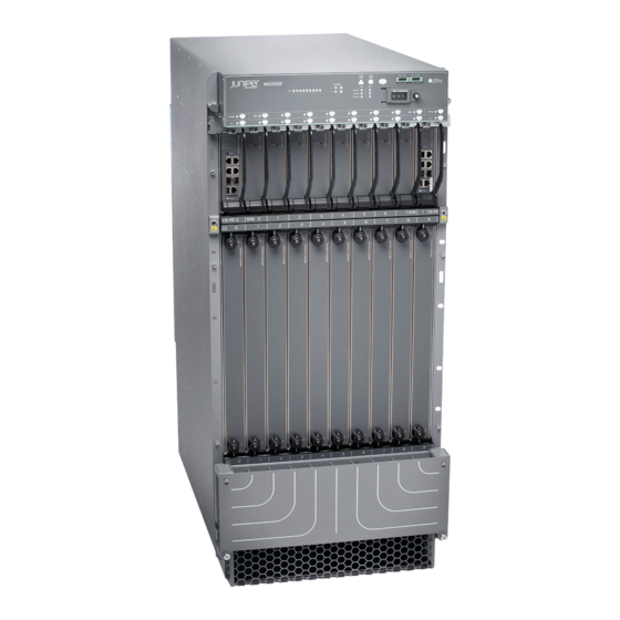
MX2008 3D Universal Edge Router
Quick Start
March 2017
Part Number: 530-073846
Revision 01
Contents
Copyright © 2017, Juniper Networks, Inc.
This document describes how to install the Juniper Networks
Edge Router.
MX2008 Quick Start Description . . . . . . . . . . . . . . . . . . . . . . . . . . . . . . . . . . . . . . . 3
Step 1: Prepare the Site for Installation . . . . . . . . . . . . . . . . . . . . . . . . . . . . . . . . . . . 5
Rack-Mounting Requirements . . . . . . . . . . . . . . . . . . . . . . . . . . . . . . . . . . . . . . 5
Tools Required to Unpack and Prepare the Router for Installation . . . . . . . . . . 9
Step 2: Install the Mounting Hardware . . . . . . . . . . . . . . . . . . . . . . . . . . . . . . . . . . . 11
Step 3: Install the Router . . . . . . . . . . . . . . . . . . . . . . . . . . . . . . . . . . . . . . . . . . . . . 13
Unpack the Router . . . . . . . . . . . . . . . . . . . . . . . . . . . . . . . . . . . . . . . . . . . . . . . 13
Remove Components . . . . . . . . . . . . . . . . . . . . . . . . . . . . . . . . . . . . . . . . . . . . 15
Install the Router by Using a Pallet Jack with Attachment . . . . . . . . . . . . . . . 20
Install the Pallet Jack Attachment . . . . . . . . . . . . . . . . . . . . . . . . . . . . . . 20
Use the Pallet Jack with Attachment to Install the Router . . . . . . . . . . . . 21
Install the Router Using a Router Transport Kit . . . . . . . . . . . . . . . . . . . . . . . . 24
Unpack the Router Transport Kit . . . . . . . . . . . . . . . . . . . . . . . . . . . . . . . . 24
Install the Router Transport Kit onto the Router . . . . . . . . . . . . . . . . . . . 26
Secure the Router to the Transport Platform . . . . . . . . . . . . . . . . . . . . . . 28
Use the Router Transport Kit to Install the Router in a Four-Post
Rack . . . . . . . . . . . . . . . . . . . . . . . . . . . . . . . . . . . . . . . . . . . . . . . . . . 30
Use the Router Transport Kit to Install the Router in an Open-Frame
Rack . . . . . . . . . . . . . . . . . . . . . . . . . . . . . . . . . . . . . . . . . . . . . . . . . . . 37
Step 4: Connect the Grounding Cable . . . . . . . . . . . . . . . . . . . . . . . . . . . . . . . . . . . 41
Step 5: Reinstall Components . . . . . . . . . . . . . . . . . . . . . . . . . . . . . . . . . . . . . . . . . 42
Step 6: Connect External Devices and Line Card Cables . . . . . . . . . . . . . . . . . . . . 43
Connect to a Network for Out-of-Band Management . . . . . . . . . . . . . . . . . . 43
Connect a Management Console . . . . . . . . . . . . . . . . . . . . . . . . . . . . . . . . . . . 43
Connect the Line Card Cables . . . . . . . . . . . . . . . . . . . . . . . . . . . . . . . . . . . . . 44
®
MX2008 3D Universal
1
Advertisement
Table of Contents

Related Manuals for Juniper MX2008


Summary of Contents for Juniper MX2008
-
Page 1: Table Of Contents
MX2008 Quick Start Description ........ - Page 2 MX2008 3D Universal Edge Router Quick Start Step 7: Connect Power Cables ........45 Connect Power to a Three-Phase Delta AC Power Distribution Module .
-
Page 3: Mx2008 Quick Start Description
24-U rack space from access during installation. The MX2008 router is 24 rack units (U) tall. One router can be installed in an open-frame rack, four-post rack, or cabinet. The MX2008 router has 10 dedicated line-card slots, which means a maximum of 10 Modular Port Concentrators (MPCs) including Adapter cards and Modular Interface Cards (MICs) can be installed on MX2008. - Page 4 MX2008 3D Universal Edge Router Quick Start For a list of the supported MPCs and MICs, see the MX Series Interface Module Reference Copyright © 2017, Juniper Networks, Inc.
-
Page 5: Step 1: Prepare The Site For Installation
The router must be installed into a rack or cabinet that is secured to the building structure. The cabinet must be clear of any hardware, device, rack, or cabinet component that obstructs the 24-U rack space from being accessed during installation. Copyright © 2017, Juniper Networks, Inc. - Page 6 MX2008 3D Universal Edge Router Quick Start Figure 1: MX2008 Rack Clearance and Router Dimensions for Four-Post Rack Installation Copyright © 2017, Juniper Networks, Inc.
-
Page 7: Moving Requirements And Guidelines For Using A Router Transport Kit
Moving Requirements and Guidelines for Using a Router Transport Kit Figure 2: MX2008 Rack Clearance and Router Dimensions for Open-Frame Rack Installation Moving Requirements and Guidelines for Using a Router Transport Kit The router requires a minimum 42 in. (106.7 cm) diameter of space to turn the chassis... - Page 8 MX2008 3D Universal Edge Router Quick Start Figure 3: Turning Diameter of the Router Transport Kit 42 in (106.7 cm) The weight of the router transport kit is 138.5 lb (63 kg). The maximum recommended height the router should be lifted from the floor by using the router transport kit is 1.5 in.
-
Page 9: Tools Required To Unpack And Prepare The Router For Installation
Figure 5: Measurements of the Router Transport Kit Installed on the MX2008 (Front View) Tools Required to Unpack and Prepare the Router for Installation To unpack the router and prepare for installation, you need the following tools and equipment: Copyright © 2017, Juniper Networks, Inc. - Page 10 MX2008 3D Universal Edge Router Quick Start NOTE: We recommend that you install the MX2008 by using a pallet jack with attachment or a router transport kit. Router transport kit (model number MX2K-TRNSPRT-KIT) Standard pallet jack—48 in. (121.92 cm) deep x 27 in. (68.58 cm) wide.
-
Page 11: Step 2: Install The Mounting Hardware
NOTE: There must be a minimum of 24-U unobstructed front-to-back usable rack space when installing the MX2008 router into a four-post rack or cabinet. Partially insert screws into the open holes in the rear flanges of the four-post mounting... - Page 12 24 in. (60.96 cm) through 30 in. (76.2 cm) to accommodate different types of racks rails. If you are installing the MX2008 router into a network cabinet, make sure that no hardware, device, rack, or cabinet component obstructs the 24-U rack space from access during installation.
-
Page 13: Step 3: Install The Router
Because of the router’s size and weight—up to 742.2 lb (336.66 kg) for AC chassis and 664.8 lb (301.55 kg) for DC chassis depending on configuration—we strongly recommend that you install the router by using a router transport kit or a pallet jack with pallet jack attachment. Copyright © 2017, Juniper Networks, Inc. - Page 14 MX2008 3D Universal Edge Router Quick Start NOTE: The router is maximally protected inside the shipping crate (see Figure 7 on page 14). Do not unpack it until you are ready to begin installation. Figure 7: MX2008 Shipping Crate Door...
-
Page 15: Remove Components
Remove Components The router might have field replacement units (FRUs) installed. Remove these FRUs from the MX2008 router before installing the router into a rack or cabinet (see Figure 8 on page Figure 9 on page... - Page 16 MX2008 3D Universal Edge Router Quick Start Remove field replacement units (FRUs) from the front of the MX2008 router before you install the router. See Table 1 on page 16 for information about MX2008 router components. Table 1: Components to Remove from the Front of the MX2008 Router Component Component No.
- Page 17 Remove Components Remove field replacement units (FRUs) from the rear of an AC-powered MX2008 router before you install the router. See Table 2 on page 17 for information about MX2008 router components. Table 2: Components to Remove from the Rear of an AC-Powered...
- Page 18 MX2008 3D Universal Edge Router Quick Start Figure 10: Components to Remove from the Rear of a DC-Powered MX2008 Router Remove field replacement units (FRUs) from the rear of a DC-powered MX2008 router before you install the router. See Table 3 on page 18 for information about MX2008 router components.
- Page 19 Label each component as you remove it so you can reinstall it in the correct location. NOTE: The MX2008 PSMs can be installed in any order in the chassis. Immediately store each removed component in an electrostatic bag. Do not stack removed components. Lay each one on a flat surface.
-
Page 20: Install The Router By Using A Pallet Jack With Attachment
MX2008 3D Universal Edge Router Quick Start Figure 11: Removing Lower Fan Trays WARNING: Before removing a fan tray, make sure that the fan blades have stopped completely. NOTE: For complete instructions on removing router components, see the MX2008 3D Universal Edge Router Hardware Guide. -
Page 21: Use The Pallet Jack With Attachment To Install The Router
Ensure that the rack or cabinet is in its permanent location and is secured to the building. Ensure that the installation site allows adequate clearance for both airflow and maintenance. For details, see the MX2008 3D Universal Edge Router Hardware Guide. - Page 22 Using the pallet jack, position the router in front of the rack or cabinet, centering it in front of the rack. NOTE: If you are installing the MX2008 router into a network cabinet, make sure that no hardware, device, rack, or cabinet component obstructs the 24-U rack space from access during installation.
- Page 23 Figure 14: Loading the MX2008 Router into a Four-Post Rack Copyright © 2017, Juniper Networks, Inc.
-
Page 24: Install The Router Using A Router Transport Kit
MX2008 3D Universal Edge Router Quick Start Figure 15: Loading the MX2008 Router into an Open-Frame Rack Install the Router Using a Router Transport Kit Unpack the Router Transport Kit on page 24 Install the Router Transport Kit onto the Router on page 26... - Page 25 Position the shipping crate with the arrows pointing up. Remove the metal clips on the shipping crate that secure the top and front to the crate (see Figure 17 on page 25). Figure 17: Open Router Transport Kit Shipping Crate Copyright © 2017, Juniper Networks, Inc.
-
Page 26: Install The Router Transport Kit Onto The Router
Install the Router Transport Kit onto the Router NOTE: The router transport kit can be purchased from Juniper Networks. The router transport kit includes the following components: Router transport platform Router transport left and right mounting plates with adjustable wheel assembly Copyright ©... - Page 27 Align the left router transport mounting plate and wheel assembly (indicated by left arrow shown on the assembly) with the holes on the left side of the chassis (see Figure 20 on page 28). Copyright © 2017, Juniper Networks, Inc.
-
Page 28: Secure The Router To The Transport Platform
Using a number 3 Phillips screwdriver, tighten the captive screws to secure the router transport mounting plate and wheel assembly to the chassis. Figure 20: Installing the Router Transport Kit onto the MX2008 Router Secure the Router to the Transport Platform Ensure that the rack is in its permanent location and is secured to the building. - Page 29 Figure 21: Securing the Crate Door to the Shipping Crate Platform NOTE: An empty MX2008 weighs approximately 261 lb (118.39 kg). Using a two-person team on either side of the chassis, turn the handles on the router transport kit 4–5 times until the chassis is raised approximately 1 in. (2.54 cm), making sure that the chassis is level.
-
Page 30: Rack
MX2008 3D Universal Edge Router Quick Start CAUTION: Do not lift the router by using the handles on the shipping covers. Use these handles only to help position the router. Position the router transport platform directly under the router, aligning the router transport platform with the bottom of the chassis by adjusting the four leveling mounts. - Page 31 The router transport kit handles can be removed to accommodate aisle width. Install the winch mount bracket to the rear rack rails by using the six captive screws, and tighten the screws (see Figure 24 on page 32). Copyright © 2017, Juniper Networks, Inc.
- Page 32 MX2008 3D Universal Edge Router Quick Start Figure 24: Installing the Winch Mount Bracket to Rack Rails Adjust the height of the router by turning the handles clockwise until the router transport platform is aligned with the surface of the mounting shelf and slightly higher...
- Page 33 Use the Router Transport Kit to Install the Router in a Four-Post Rack Figure 25: Aligning the MX2008 Router with the Rack Mounting Shelf Unlock the four toggle latches that secure the router transport platform to the router transport mounting plate and wheel assembly.
- Page 34 MX2008 3D Universal Edge Router Quick Start Figure 26: Removing the Router Transport Mounting Plate and Wheel Assembly Attach the winch strap to the winch strap plate at the rear of the router (see Figure 27 on page 35). Copyright © 2017, Juniper Networks, Inc.
- Page 35 Figure 27: Attaching the Winch Strap to the Winch Strap Plate Attach a 1-1/8 in. (28.57 mm) torque-controlled driver or socket wrench to the winch mechanism and turn clockwise to start pulling the chassis into the rack (see Figure 28 on page 36). Copyright © 2017, Juniper Networks, Inc.
- Page 36 MX2008 3D Universal Edge Router Quick Start Figure 28: Pulling the MX2008 into the Rack NOTE: A four-person team is needed to carefully guide the router into the rack while operating the winch. If the router is not pulled all the way into the rack by the winch...
-
Page 37: Rack
To install the MX2008 in an open-frame rack by using a router transport kit: Using the router transport platform, position the router in front of the rack or cabinet, centering it in front of the rack. - Page 38 MX2008 3D Universal Edge Router Quick Start Figure 29: Aligning the MX2008 Router with the Rack Unlock the four toggle latches that secure the router transport platform to the router transport mounting plate and wheel assembly. Lift the wheels up by turning the handles counterclockwise so that the weight of the router is on the router transport platform.
- Page 39 Figure 30: Removing the Router Transport Mounting Plate and Wheel Assembly Grasping the handles on the shipping covers, carefully slide the router into the rack until the center-mounting brackets contact the rack rails (see Figure 31 on page 40). Copyright © 2017, Juniper Networks, Inc.
- Page 40 MX2008 3D Universal Edge Router Quick Start Figure 31: Sliding the MX2008 into the Open-Frame Rack NOTE: A four-person team is needed to carefully guide the router into the rack. NOTE: There must be a minimum of 24-U of usable rack space when you install the MX2008 into a 24-U rack.
-
Page 41: Step 4: Connect The Grounding Cable
Attach an ESD grounding strap to your bare wrist, and connect the strap to one of the ESD points on the chassis. For more information about ESD, see the MX2008 3D Universal Edge Router Hardware Guide. Place the grounding cable lug over the grounding points. The upper pair is sized for UNC 1/4-20 bolts, and the lower pair is sized for M6 bolts. -
Page 42: Step 5: Reinstall Components
MX2008 3D Universal Edge Router Quick Start Step 5: Reinstall Components To reinstall the components in the router: Take each component out of its electrostatic bag, and identify the slot on the component where it will be connected. NOTE: Remove the shipping covers before installing router components. -
Page 43: Step 6: Connect External Devices And Line Card Cables
You must use shielded cables for the following ports: console, management, auxiliary, USB, and clocking ports. Connect a Management Console Turn off the power to the management device. Plug one end of an RJ-45 Ethernet cable into the port on the RCB. CONSOLE Copyright © 2017, Juniper Networks, Inc. -
Page 44: Connect The Line Card Cables
MX2008 3D Universal Edge Router Quick Start Plug the female DB-9 adapter end of the cable into the device's serial port. CAUTION: You must use shielded cables for the following ports: console, management, auxiliary, USB, and clocking ports. Connect the Line Card Cables Have ready a length of the type of cable used by the MPCs or MICs. -
Page 45: Step 7: Connect Power Cables
Depending on your configuration, your router uses either AC or DC power distribution modules (PDMs). Perform the appropriate procedures for each PDM in your router. For more information about PDMs, see the MX2008 3D Universal Edge Router Hardware Guide. Connect Power to a Three-Phase Delta AC Power Distribution Module on page 45... - Page 46 PDM before the PDM can be removed from the chassis. The MX2008 chassis is not sensitive to phase rotation sequence—either clockwise or counter clockwise will operate correctly.
- Page 47 The three-phase delta AC PDM terminal blocks will be flipped depending on which slot the PDM gets plugged into. CAUTION: Wire label configuration is for Juniper Networks supplied cable only. If you are using your own cable, make sure you use the proper connections.
- Page 48 MX2008 3D Universal Edge Router Quick Start WARNING: Power connections must be performed by a licensed electrician only. Verify that the power cable connections are correct. Screw the retaining nut onto the AC power cord to secure it to the metal wiring compartment.
-
Page 49: Connect Power To A Three-Phase Wye Ac Power Distribution Module
AC wire gauge). NOTE: The terminal connections have either slotted screws or hex screws. Use a 1/4-in. slotted screwdriver for the slotted screws. Use a 5/32-in. (4-mm) Allen wrench for the 5/16-in. hex screws. Copyright © 2017, Juniper Networks, Inc. - Page 50 PDM before the PDM can be removed from the chassis. The MX2008 chassis is not sensitive to phase rotation sequence—either clockwise or counter clockwise will operate correctly.
- Page 51 Power connections must be performed by a licensed electrician only. Verify that the power cable connections are correct. Screw the retaining nut onto the AC power cord to secure it to the metal wiring compartment. Copyright © 2017, Juniper Networks, Inc.
- Page 52 MX2008 3D Universal Edge Router Quick Start Reinstall the metal PDM wiring cover, and using a number 2 Phillips (+) screwdriver, tighten the four captive screws on the metal AC wiring compartment. Use the provided plastic cable tie to fasten the AC power cord to the PDM.
-
Page 53: Connect Ac Power Supply Modules
Connect AC Power Supply Modules Connect AC Power Supply Modules To install an MX2008 AC power supply module (PSM): Verify that the power switch on the PSM is in the off ( ) position (see Figure 38 on page 53). - Page 54 PWR OK about MX2008 AC PSM LEDs. NOTE: The MX2008 systems configured for three-phase wye AC input power must use only three-phase wye AC PDMs and AC PSMs. Systems configured for three-phase delta AC input power must use three-phase delta AC PDMs and AC PSMs. AC and DC PSMs or PDMs must not be mixed within a single system.
-
Page 55: Connect Power To A Dc Power Distribution Module
Connect Power to a DC Power Distribution Module Figure 39: MX2008 AC Power Supply Module Front View NOTE: Each PSM slot not occupied by an AC PSM must be covered by a PSM blank panel. Connect Power to a DC Power Distribution Module Attach an electrostatic discharge (ESD) grounding strap to your bare wrist, and connect the strap to one of the ESD points on the chassis. - Page 56 Attach the negative (–) DC source power cable lug to the (input) terminal. –48V Table 9 on page 56 describes the DC operating range specifications. Table 9: MX2008 DC Power System Input Voltage Item Specification DC input voltage Operating range: –40 through –72 VDC...
-
Page 57: Connect Dc Power Supply Modules
Connect each DC power cable to the appropriate external DC power source. NOTE: For information about connecting to external DC power sources, see the MX2008 3D Universal Edge Router Hardware Guide. Switch on the external circuit breakers to provide voltage to the DC power source cable leads. - Page 58 Tighten the two captive screws to secure the PSM to the chassis. NOTE: The MX2008 systems configured for DC input power must use only DC PDMs and DC PSMs. AC and DC PSMs or PDMs must not be mixed within a single system.
- Page 59 DC input is detected but voltage is out of range. – DC input to the PSM is not present. Repeat Steps through for installing PSMs in slots , and , where required. Figure 42: MX2008 DC Power Supply Module Front View Copyright © 2017, Juniper Networks, Inc.
- Page 60 MX2008 3D Universal Edge Router Quick Start NOTE: Each PSM slot not occupied by a DC PSM must be covered by a PSM blank panel. Copyright © 2017, Juniper Networks, Inc.
-
Page 61: Step 8: Perform Initial Software Configuration
Junos OS configuration guides. Check the LEDs on the craft interface to verify the hardware status after reinstalling or powering on the MX2008 router. For a list of system status verification commands, see the MX2008 3D Universal Edge Router Hardware Guide at http://www.juniper.net/techpubs/... -
Page 62: Configure System Attributes
MX2008 3D Universal Edge Router Quick Start Set the user account class to super-user [edit] root@# set system login user user-name class super-user Configure System Attributes For more information about configuring the backup routing and static routes, see the Junos OS Administration Library. -
Page 63: Commit The Configuration
Optionally, configure additional properties by adding the necessary configuration statements. Then commit the changes to activate them on the router. [edit] root@host# commit When you have finished configuring the router, exit configuration mode. [edit] root@host# exit root@host> Copyright © 2017, Juniper Networks, Inc. -
Page 64: Safety Warnings
Only trained and qualified personnel should install or replace the router. Perform only the procedures described in this Quick Start or in the MX2008 3D Universal Edge Router Hardware Guide. Other services should be performed by authorized service personnel only. - Page 65 Allow 2.8 in. (7 cm) between the side of the chassis and any non-heat-producing surface such as a wall. Four people are required to move the MX2008 router. Always remove the front and rear shipping covers before removing the components.
-
Page 66: Compliance Statements For Nebs
The battery return connection is to be treated as an isolated DC return (i.e. DC-I), as defined in GR-1089-CORE. For Juniper Networks systems with AC power supplies, an external surge protective device (SPD) must be used at the AC power source. -
Page 67: Israel
Compliance Statements for EMC Requirements for Juniper Networks Devices Israel Translation from Hebrew—Warning: This product is Class A. In residential environments, the product might cause radio interference, and in such a situation, the user might be required to take adequate measures. -
Page 68: Junos Os Documentation And Release Notes
7 days a week, 365 days a year. Self-Help Online Tools and Resources For quick and easy problem resolution, Juniper Networks has designed an online self-service portal called the Customer Support Center (CSC) that provides you with the following features: Find CSC offerings: http://www.juniper.net/customers/support/... -
Page 69: Opening A Case With Jtac
Juniper Networks, Junos, Steel-Belted Radius, NetScreen, and ScreenOS are registered trademarks of Juniper Networks, Inc. in the United States and other countries. The Juniper Networks Logo, the Junos logo, and JunosE are trademarks of Juniper Networks, Inc. All other trademarks, service marks, registered trademarks, or registered service marks are the property of their respective owners.
Need help?
Do you have a question about the MX2008 and is the answer not in the manual?
Questions and answers