Table of Contents
Advertisement
Quick Links
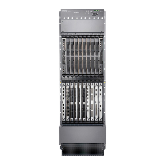
MX2010 3D Universal Edge Router
Quick Start
January 2014
Contents
Copyright © 2014, Juniper Networks, Inc.
This document describes how to install the Juniper Networks
Edge Router.
MX2010 Quick Start Description . . . . . . . . . . . . . . . . . . . . . . . . . . . . . . . . . . . . . . . . 3
Step 1: Prepare the Site for Installation . . . . . . . . . . . . . . . . . . . . . . . . . . . . . . . . . . . 4
Rack-Mounting Requirements . . . . . . . . . . . . . . . . . . . . . . . . . . . . . . . . . . . . . . 4
Moving Requirements and Guidelines Using a Router Transport Kit . . . . . . . . 6
Tools Required to Unpack and Prepare the Router for Installation . . . . . . . . . . 9
Step 2: Install the Mounting Hardware . . . . . . . . . . . . . . . . . . . . . . . . . . . . . . . . . . 10
Install the Mounting Hardware . . . . . . . . . . . . . . . . . . . . . . . . . . . . . . . . . . . . . 10
Step 3: Install the Router . . . . . . . . . . . . . . . . . . . . . . . . . . . . . . . . . . . . . . . . . . . . . 12
Unpack the Router . . . . . . . . . . . . . . . . . . . . . . . . . . . . . . . . . . . . . . . . . . . . . . . 12
Remove Components . . . . . . . . . . . . . . . . . . . . . . . . . . . . . . . . . . . . . . . . . . . . 14
Install the Router Using a Pallet Jack with Attachment . . . . . . . . . . . . . . . . . . 19
Install the Pallet Jack Attachment . . . . . . . . . . . . . . . . . . . . . . . . . . . . . . . 19
Use the Pallet Jack with Attachment to Install the Router . . . . . . . . . . . 20
Install the Router Using a Router Transport Kit . . . . . . . . . . . . . . . . . . . . . . . . 24
Unpack the Router Transport Kit . . . . . . . . . . . . . . . . . . . . . . . . . . . . . . . . 24
Install the Router Transport Kit onto the Router . . . . . . . . . . . . . . . . . . . 26
Secure the Router Transport Platform to the Router . . . . . . . . . . . . . . . . 28
Use the Router Transport Kit to Install the Router in a Four-Post
Rack . . . . . . . . . . . . . . . . . . . . . . . . . . . . . . . . . . . . . . . . . . . . . . . . . . . 31
Use the Router Transport Kit to Install the Router In an Open-Frame
Rack . . . . . . . . . . . . . . . . . . . . . . . . . . . . . . . . . . . . . . . . . . . . . . . . . . 38
Step 4: Connect the Grounding Cable . . . . . . . . . . . . . . . . . . . . . . . . . . . . . . . . . . . 44
Step 5: Reinstall Components . . . . . . . . . . . . . . . . . . . . . . . . . . . . . . . . . . . . . . . . . 45
Step 6: Connect External Devices and Line Card Cables . . . . . . . . . . . . . . . . . . . . 46
Connect to a Network for Out-of-Band Management . . . . . . . . . . . . . . . . . . 46
Connect a Management Console . . . . . . . . . . . . . . . . . . . . . . . . . . . . . . . . . . 46
Connect the Line Card Cables . . . . . . . . . . . . . . . . . . . . . . . . . . . . . . . . . . . . . 46
Step 7: Connect Power Cables . . . . . . . . . . . . . . . . . . . . . . . . . . . . . . . . . . . . . . . . 48
®
MX2010 3D Universal
1
Advertisement
Table of Contents

Subscribe to Our Youtube Channel
Related Manuals for Juniper MX2010 3D


Summary of Contents for Juniper MX2010 3D
-
Page 1: Table Of Contents
MX2010 3D Universal Edge Router Quick Start January 2014 ® This document describes how to install the Juniper Networks MX2010 3D Universal Edge Router. Contents MX2010 Quick Start Description ........3 Step 1: Prepare the Site for Installation . - Page 2 MX2010 3D Universal Edge Router Quick Start Connect AC Power Supply Modules ....... . . 54 Connect Power to a DC Power Distribution Module .
-
Page 3: Mx2010 Quick Start Description
MX2010 3D Universal Edge Router Hardware Guide http://www.juniper.net/techpubs/ The MX2010 3D Universal Edge Router with the standard cable manager is 34 rack units (U) tall, 59.50 in. (151.13 cm) of rack space. One router with the standard cable manager can be installed in a single rack or cabinet. -
Page 4: Step 1: Prepare The Site For Installation
MX2010 3D Universal Edge Router Quick Start Step 1: Prepare the Site for Installation Rack-Mounting Requirements on page 4 Moving Requirements and Guidelines Using a Router Transport Kit on page 6 Tools Required to Unpack and Prepare the Router for Installation on page 9 Rack-Mounting Requirements You can install the router in a open-frame rack, four-post rack, or cabinet. - Page 5 34-U rack space from being access during installation. Figure 1: MX2010 Rack Clearance and Router Dimensions for Four-Post Rack 59.50 in (151.13 cm) 19 in 36.20 in (48.26 cm) (91.95 cm) 19.2 in (48.768 cm) Copyright © 2014, Juniper Networks, Inc.
-
Page 6: Moving Requirements And Guidelines Using A Router Transport Kit
MX2010 3D Universal Edge Router Quick Start Figure 2: MX2010 Rack Clearance and Router Dimensions for Open-Frame Rack 59.50 in (151.13 cm) 36.20 in (91.95 cm) 19 in (48.26 cm) 19.2 in (48.768 cm) Moving Requirements and Guidelines Using a Router Transport Kit The router requires a minimum 42 in. - Page 7 The side view measurements of the router with the router transport kit installed is: 59.5 in. (151.1 cm) high and 36.20 in. (91.95 cm) wide, with the transport kit measuring 23.40 in. (59.4 cm) high (see Figure 4 on page Copyright © 2014, Juniper Networks, Inc.
- Page 8 MX2010 3D Universal Edge Router Quick Start Figure 4: Measurements of the Router Transport Kit Installed on the MX2010 (Side View) Rear Front 59.50 in (151.1 cm) 23.40 in (59.4 cm) 36.20 in (91.95 cm) The front view measurements of the router with the router transport kit installed is 30.78 in.
-
Page 9: Tools Required To Unpack And Prepare The Router For Installation
9/16-in. or 14-mm open-end or socket wrench with extension to remove bracket bolts from the shipping pallet Electrostatic discharge wrist strap Antistatic mat NOTE: We recommend that you install the MX2010 using a pallet jack with attachment or a router transport kit. Copyright © 2014, Juniper Networks, Inc. -
Page 10: Step 2: Install The Mounting Hardware
MX2010 3D Universal Edge Router Quick Start Step 2: Install the Mounting Hardware Install the Mounting Hardware on page 10 Install the Mounting Hardware A mounting shelf is required for installing the router in a four-post rack or cabinet. The shelf is not required for installing the router in an open-frame rack. - Page 11 MX2010 router into a four-post rack or cabinet. NOTE: If you are installing the MX2010 router into a network cabinet, make sure that no hardware, device, rack, or cabinet component obstructs the 34-U rack space from access during installation. Copyright © 2014, Juniper Networks, Inc.
-
Page 12: Step 3: Install The Router
MX2010 3D Universal Edge Router Quick Start Step 3: Install the Router Unpack the Router on page 12 Remove Components on page 14 Install the router using one of the following procedures: Install the Router Using a Pallet Jack with Attachment on page 19... - Page 13 Open all the latches on the shipping crate. Remove the front door of the shipping crate and set it aside. Slide the remainder of the shipping crate off the pallet. This requires a minimum of a two person team. Copyright © 2014, Juniper Networks, Inc.
-
Page 14: Remove Components
MX2010 3D Universal Edge Router Quick Start Remove the foam covering the top of the router. Remove the pallet jack attachment, if ordered. See “Unpack the Router Transport Kit” on page 24 for instructions on how to unpack and install the router transport kit. - Page 15 Component No. Description Slots Number of FRUs Craft interface – Switch Fabric Boards 0 through 7 (SFBs) Control Board and 0 and 1 Routing Engine (CB-RE) MPCs with ADCs and 0 through 9 MICs Copyright © 2014, Juniper Networks, Inc.
- Page 16 MX2010 3D Universal Edge Router Quick Start Figure 9: Components to Remove from the Rear of a AC-Powered MX2010 Router Remove field replacement units (FRUs) from the rear of the MX2010 router before you install the router. See Table 2 on page 16 for information on MX2010 router components.
- Page 17 DC PSM 0 through 8 PSM air filter – DC PDM PDM0 DC cable manager – Fan tray air filter – Lower fan trays (two) Fan tray 0 and fan tray 1 (behind access door) Copyright © 2014, Juniper Networks, Inc.
- Page 18 MX2010 3D Universal Edge Router Quick Start To remove the components from the router: Slide each component out of the chassis evenly so that it does not become stuck or damaged. Label each component as you remove it so you can reinstall it in the correct location.
-
Page 19: Install The Router Using A Pallet Jack With Attachment
Figure 12: Removing Lower Fan Trays NOTE: For complete instructions on removing router components, see the MX2010 3D Universal Edge Router Hardware Guide Install the Router Using a Pallet Jack with Attachment Install the Pallet Jack Attachment on page 19... -
Page 20: Use The Pallet Jack With Attachment To Install The Router
MX2010 3D Universal Edge Router Quick Start Using a 9/16-in. (14 mm) drive socket wrench, loosen the torque fasteners that are located on the four adjustable pallet jack attachment brackets. Adjust the four pallet jack attachment brackets until they fit under the pallet jack legs. - Page 21 NOTE: If you are installing the MX2010 router into a network cabinet, make sure that no hardware, device, rack, or cabinet component obstructs the 34-U rack space from access during installation. Copyright © 2014, Juniper Networks, Inc.
- Page 22 MX2010 3D Universal Edge Router Quick Start Using the pallet jack, lift the chassis approximately 0.75 in. above the surface of the mounting shelf, and position it as close as possible to the shelf. NOTE: Due to the short lift capability of the pallet jack, it is recommended to install the router on the bottom of the rack.
- Page 23 Use the Pallet Jack with Attachment to Install the Router Figure 15: Loading the MX2010 Router into a Four-Post Rack Copyright © 2014, Juniper Networks, Inc.
-
Page 24: Install The Router Using A Router Transport Kit
MX2010 3D Universal Edge Router Quick Start Figure 16: Loading the MX2010 Router into a Open-Frame Rack Install the Router Using a Router Transport Kit Unpack the Router Transport Kit on page 24 Install the Router Transport Kit onto the Router on page 26... - Page 25 Position the shipping crate with the arrows pointing up. Remove the metal clips on the shipping crate that secure the top and front to the crate (see Figure 18 on page 25). Figure 18: Open Router Transport Kit Shipping Crate Copyright © 2014, Juniper Networks, Inc.
-
Page 26: Install The Router Transport Kit Onto The Router
Install the Router Transport Kit onto the Router NOTE: The router transport kit be purchased from Juniper Networks. The router transport kit includes the following components: Router transport platform Router transport left and right mounting plates with adjustable wheel assembly... - Page 27 9/16-in. (14 mm) socket wrench, and a number 2 Phillips screwdriver, and set them aside. Align the left router transport mounting plate and wheel assembly (indicated by left arrow) with the holes on the left side of the chassis (see Figure 21 on page 28). Copyright © 2014, Juniper Networks, Inc.
-
Page 28: Secure The Router Transport Platform To The Router
MX2010 3D Universal Edge Router Quick Start Using a number 3 Phillips screwdriver tighten the captive screws to secure the router transport mounting plate and wheel assembly to the chassis. Align the right router transport mounting plate and wheel assembly (indicated by right... - Page 29 Turn the four wheels on the router transport kit toward the rear of the chassis. Grasping the handles on the shipping covers, carefully guide the chassis down the crate ramp to the rack location. Copyright © 2014, Juniper Networks, Inc.
- Page 30 MX2010 3D Universal Edge Router Quick Start WARNING: Do not push or pull the router fast during transporting. Using excessive speed can cause the wheels to turn abruptly and tilt the router over. CAUTION: Do not lift the router using the handles on the shipping covers.
-
Page 31: Rack
Four people are needed to install the router into a rack. CAUTION: Before front mounting the router in a rack, have a qualified technician verify that the rack is strong enough to support the router's weight and is adequately supported at the installation site. Copyright © 2014, Juniper Networks, Inc. - Page 32 MX2010 3D Universal Edge Router Quick Start Install the winch strap plate to the rear of the router by tightening the four captive screws (see Figure 24 on page 32). Figure 24: Installing Winch Strap Plate (Four-Post Rack) Using a four person team, transport the router to the rack installation location and center it in front of the mounting shelf.
- Page 33 (see Figure 26 on page 34). NOTE: Make sure the bubbles within the T-shaped levels are between the lines, indicating the router is level. Copyright © 2014, Juniper Networks, Inc.
- Page 34 MX2010 3D Universal Edge Router Quick Start Adjust the four leveling mounts on the router transport platform until all four leveling mounts rest firmly on the ground (see Figure 26 on page 34). Figure 26: Align the MX2010 Router with Rack Mounting Shelf Unlock the four toggle latches that secure the router transport platform to the router transport mounting plate and wheel assembly.
- Page 35 Figure 27 on page 35). Figure 27: Remove Router Transport Mounting Plate and Wheel Assembly Attach the winch strap to the winch strap plate at the rear of the router (see Figure 28 on page 36). Copyright © 2014, Juniper Networks, Inc.
- Page 36 MX2010 3D Universal Edge Router Quick Start Figure 28: Attaching Winch Strap to Winch Strap Plate Attach a 1-1/8 in. (28.57 mm) socket drive wrench to the winch mechanism and turn clockwise to start pulling the chassis into the rack (see 1 Figure 29 on page 37).
- Page 37 Use the Router Transport Kit to Install the Router in a Four-Post Rack Figure 29: Pulling the MX2010 into the Rack NOTE: A four-person team is needed to carefully guide the router into the rack while operating the winch. Copyright © 2014, Juniper Networks, Inc.
-
Page 38: Rack
MX2010 3D Universal Edge Router Quick Start NOTE: If the router isn’t pulled all the way into the rack by the winch mechanism, grasp the handles on the shipping covers and carefully slide the router onto the mounting shelf until the front-mounting flanges contact the rack rails. - Page 39 Make sure the bubbles within the T-shaped levels are between the lines, indicating the router is level. Adjust the four leveling mounts on the router transport platform until all four leveling mounts rest firmly on the ground (see Figure 30 on page 40). Copyright © 2014, Juniper Networks, Inc.
- Page 40 MX2010 3D Universal Edge Router Quick Start Figure 30: Align the MX2010 Router with Rack Mounting Shelf Unlock the four toggle latches that secure the router transport platform to the router transport mounting plate and wheel assembly. Copyright © 2014, Juniper Networks, Inc.
- Page 41 Figure 31: Remove Router Transport Mounting Plate and Wheel Assembly Grasping the handles on the shipping covers, carefully slide the router into the rack until the center mounting brackets contact the rack rails (see Figure 32 on page 42). Copyright © 2014, Juniper Networks, Inc.
- Page 42 MX2010 3D Universal Edge Router Quick Start Figure 32: Sliding the MX2010 into the Rack NOTE: A four-person team is needed to carefully guide the router into the rack. NOTE: There must be a minimum of 45-U of usable rack space when installing the MX2010 into a 45-U rack.
- Page 43 Reassemble the router transport kit, and set aside. Copyright © 2014, Juniper Networks, Inc.
-
Page 44: Step 4: Connect The Grounding Cable
MX2010 3D Universal Edge Router Quick Start Step 4: Connect the Grounding Cable Attach an electrostatic discharge (ESD) grounding strap to your bare wrist, and connect the strap to an approved site ESD grounding point. See the instructions for your site. -
Page 45: Step 5: Reinstall Components
Slide each component into the chassis evenly so that it does not become stuck or damaged. Tighten the captive screws, and secure all levers for each component. NOTE: Make sure that all empty slots are covered with a blank panel before operating the router. Copyright © 2014, Juniper Networks, Inc. -
Page 46: Step 6: Connect External Devices And Line Card Cables
MX2010 3D Universal Edge Router Quick Start Step 6: Connect External Devices and Line Card Cables Figure 34: Connect External Devices and MPC Cables Connect to a Network for Out-of-Band Management on page 46 Connect a Management Console on page 46... - Page 47 CAUTION: Do not let fiber-optic cable hang free from the connector. Do not allow fastened loops of cable to dangle, which stresses the cable at the fastening point. Copyright © 2014, Juniper Networks, Inc.
-
Page 48: Step 7: Connect Power Cables
MX2010 3D Universal Edge Router Quick Start Step 7: Connect Power Cables Depending on your configuration, your router uses either AC or DC PDMs. Perform the appropriate procedures for each PDM in your router. For more information on PDMs, see... - Page 49 Insert the wire labeled into the input terminal labeled d. Insert the wire labeled into the input terminal labeled Figure 35: Connecting Power to a Three-Phase Delta AC Power Distribution Module Copyright © 2014, Juniper Networks, Inc.
- Page 50 PDM gets plugged into. CAUTION: Wire label configuration is for Juniper Networks supplied cable only. If using your own cable, make sure you use the proper connections. To connect wires to the terminal block that serves three PSMs: a.
-
Page 51: Connect Power To A Three-Phase Wye Ac Power Distribution Module
Put the wires of the AC power cord through the hole of the retaining nut and rubber grommet. Put the wires of the AC power cord through the hole of the metal wiring compartment. Copyright © 2014, Juniper Networks, Inc. - Page 52 MX2010 3D Universal Edge Router Quick Start Connect the wires to the AC terminal block on the three-phase wye AC PDM (see Figure 36 on page 53). Loosen the input terminal or grounding point screw, insert each wire into the grounding point or input terminal, and tighten the screw (see Table 5 on page 54 for approved AC wire gauge).
- Page 53 Figure 36: Connecting Power to a Three-Phase Wye AC Power Distribution Module CAUTION: Wire label configuration is for Juniper Networks supplied cable only. If using your own cable, make sure you use the proper connections. To connect wires to the terminal block that serves three PSMs: a.
-
Page 54: Connect Ac Power Supply Modules
MX2010 3D Universal Edge Router Quick Start NOTE: The color of each AC power wire might vary. NOTE: Three-phase wye AC wire assembly kits can be purchased from Juniper Networks. Table 5: Supported Three-Phase Wye AC Wire Gauge Wire Gauge... - Page 55 AC PDMs and AC PSMs. Systems configured for three-phase delta AC input power must use three-phase delta AC PDMs and AC PSMs. AC and DC PSMs or PDMs must not be mixed within a single system. Copyright © 2014, Juniper Networks, Inc.
- Page 56 MX2010 3D Universal Edge Router Quick Start Table 6: MX2010 AC Power Supply Module LEDs Label Color State Description Green Power is functioning normally with no alarms. PWR OK Yellow PSM controller is functioning normally. – PSM is not functioning normally or the AC input voltage is out of range.
-
Page 57: Connect Power To A Dc Power Distribution Module
Attach an electrostatic discharge (ESD) grounding strap to your bare wrist, and connect the strap to one of the ESD points on the chassis. For more information about ESD, see the MX2010 3D Universal Edge Router Hardware Guide NOTE: If the DC PSMs are installed in the router, make sure the power switch is turned to the off ( ) position. - Page 58 MX2010 3D Universal Edge Router Quick Start Figure 39: Connecting Ground and DC Power Cables Cable Flat Terminal washer studs Split washer Grounding points (on chassis) CAUTION: Ensure that each power cable lug seats flush against the surface of the terminal block as you are tightening the nuts. Ensure that each nut is properly threaded onto the terminal stud.
-
Page 59: Connect Dc Power Supply Modules
In addition, a PSM failure triggers the alarm LED on the craft interface. Each PDM has an LED per feed indicating whether the feed is active or not, or whether the feed is connected properly. Copyright © 2014, Juniper Networks, Inc. - Page 60 MX2010 3D Universal Edge Router Quick Start Figure 40: Selecting DC Power Subsystem Feed Redundancy PWR OK FAULT INP0 INP1 Ensure that the voltage across the DC power source cable leads is 0 V and that there is no chance that the cable leads might become active during installation.
- Page 61 DC input is detected but voltage is out of range. – DC input to the PSM is not present. Repeat Steps through for installing PSMs in slots , and , where required. Figure 41: MX2010 DC Power Supply Module Front View Copyright © 2014, Juniper Networks, Inc.
- Page 62 MX2010 3D Universal Edge Router Quick Start NOTE: Each PSM slot not occupied by a DC PSM must be covered by a PSM blank panel. Copyright © 2014, Juniper Networks, Inc.
-
Page 63: Step 8: Perform Initial Software Configuration
Check the LEDs on the craft interface to verify the hardware status after reinstalling or powering on the MX2010 router. For a list of system status verification commands, see the MX2010 3D Universal Edge Router Hardware Guide http://www.juniper.net/techpubs/ To configure the software:... -
Page 64: Configuring System Attributes
MX2010 3D Universal Edge Router Quick Start root# set system login user user-name authentication plain-text-password New Password: password Retype new password: password Set the user account class to super-user [edit] root@# set system login user user-name class super-user Configuring System Attributes... -
Page 65: Committing The Configuration
Optionally, configure additional properties by adding the necessary configuration statements. Then commit the changes to activate them on the router. [edit] root@host# commit When you have finished configuring the router, exit configuration mode. [edit] root@host# exit root@host> Copyright © 2014, Juniper Networks, Inc. -
Page 66: Safety Warnings
MX2010 3D Universal Edge Router Quick Start Safety Warnings WARNING: See installation instructions before connecting the router. This is a summary of safety warnings. For a complete list of warnings for this router, including translations, see the MX2010 3D Universal Edge Router Hardware Guide http://www.juniper.net/techpubs/... - Page 67 Failure to observe these safety warnings can result in serious physical injury. AC power cable warning (Japan): WARNING: The attached power cable is only for this product. Do not use the cable for another product. Copyright © 2014, Juniper Networks, Inc.
-
Page 68: Compliance Statements For Nebs For The Mx2010 Router
MX2010 3D Universal Edge Router Quick Start Compliance Statements for NEBS for the MX2010 Router The equipment is suitable for installation as part of the Common Bonding Network (CBN). The equipment is suitable for installation in locations where the National Electrical Code (NEC) applies. -
Page 69: Japan
Figure 42: MX2010 Declaration of Conformity Japan Translation from Japanese—This is a Class A product. In a domestic environment this product may cause radio interference in which case the user may be required to take adequate measures. VCCI-A Copyright © 2014, Juniper Networks, Inc. -
Page 70: United States
MX2010 3D Universal Edge Router Quick Start United States The router has been tested and found to comply with the limits for a Class A digital device, pursuant to Part 15 of the FCC Rules. These limits are designed to provide reasonable protection against harmful interference when the equipment is operated in a commercial environment. -
Page 71: Junos Os Documentation And Release Notes
7 days a week, 365 days a year. Self-Help Online Tools and Resources For quick and easy problem resolution, Juniper Networks has designed an online self-service portal called the Customer Support Center (CSC) that provides you with the following features: Find CSC offerings: http://www.juniper.net/customers/support/... -
Page 72: Opening A Case With Jtac
Juniper Networks, Junos, Steel-Belted Radius, NetScreen, and ScreenOS are registered trademarks of Juniper Networks, Inc. in the United States and other countries. The Juniper Networks Logo, the Junos logo, and JunosE are trademarks of Juniper Networks, Inc. All other trademarks, service marks, registered trademarks, or registered service marks are the property of their respective owners.
Need help?
Do you have a question about the MX2010 3D and is the answer not in the manual?
Questions and answers