Samson 3766 Mounting And Operating Instructions
Pneumatic positioner
Hide thumbs
Also See for 3766:
- Mounting and operating instructions (56 pages) ,
- Mounting and operating instructions (76 pages)

Related Manuals for Samson 3766


Summary of Contents for Samson 3766
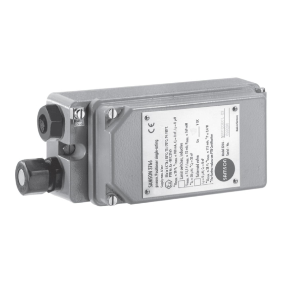
- Page 1 Pneumatic Positioner Type 3766 Fig. 1 ⋅ Type 3766 Mounting and Operating Instructions EB 8355-1 EN Edition September 2009...
- Page 2 Contents EB 8355-1 EN...
- Page 3 Internet at http://www.samson.de. Note! Positioners with model index 3766-x...x. 03 and higher are equipped with a hinged cover without vent connection. The required exhaust air connection is now included in the mount- ing accessories. If these positioners are mounted on older actuator models, make absolutely sure that there is a vent connection.
- Page 4 Design and principle of operation EB 8355-1 EN...
- Page 5 Design and principle of operation Supply Fig. 2 ⋅ Functional diagram and inside view EB 8355-1 EN...
- Page 6 Design and principle of operation EB 8355-1 EN...
- Page 7 Versions ⁄ − ⁄ ≥ − EB 8355-1 EN...
- Page 8 Technical data ≤ ≤ ≤ ≤ ≤ ≤ ≤ ≤ EB 8355-1 EN...
- Page 9 Technical data ≤ ≤ ≤ ≥ ≥ ≥ Ω Ω Ω ≤ ≤ ≤ ≤ ≤ ≤ ≤ ≤ ≤ ≤ ≤ ≤ ≤ ≤ ≤ ≤ ≤ ≤ ≤ ≤ ≤ EB 8355-1 EN...
- Page 10 Attachment to control valve Important! When any subsequent changes are made, e.g. reversing the operating direction of the positioner control loop or changing the actu- ator from “Actuator stem extends” to “Actu- ator stem retracts” or vice versa, the posi- tioner’s mounting position must be changed accordingly.
- Page 11 Direct attachment to Type 3277 Actuator Fig. 3 ⋅ Mounting pos. and signal press. conn. for Type 3277 (top) and Type 3277-5 with 120 cm (bottom) Actuators EB 8355-1 EN...
- Page 12 Direct attachment to Type 3277 Actuator Important! When a solenoid valve or a similar device is attached to the 120 cm actuator in addi- tion to the positioner, do not remove the rear M3 screw plug. In this case, the signal pressure must be transmitted from the signal pressure output to the actuator over an addi- tional connecting plate (Table 2).
- Page 13 Direct attachment to Type 3277 Actuator Important! When the valve is installed, the lateral cover of the actuator must be mounted such that the vent plug points downward. Fig. 4 ⋅ Mounting the clamp EB 8355-1 EN...
- Page 14 Direct attachment to Type 3277 Actuator Note! Only the new switchover and connecting plates can be used for new actuators (model index 01). Old and new plates cannot be interchanged. EB 8355-1 EN...
- Page 15 Attachment according to IEC 60534-6 Required mounting parts are listed in Table 5. The rated travel of the valve deter- mines which lever and range spring (Table 6) are required. Fig. 5 ⋅ Fixing the spring on the rear housing Fig.
- Page 16 Attachment according to IEC 60534-6 Caution! The pin must not slip from the bracket once it has been installed. EB 8355-1 EN...
- Page 17 Attachment according to IEC 60534-6 24 25 21 20 Fig. 7 ⋅ Attachment according to IEC 60534-6 (NAMUR) EB 8355-1 EN...
- Page 18 Attachment according to IEC 60534-6 EB 8355-1 EN...
- Page 19 Attachment to rotary actuators EB 8355-1 EN...
- Page 20 Attachment to rotary actuators Important! Use proper range spring (1 or 2)! Range spring 1 is installed by default. Important! To ensure a close physical contact between the cam follower roll and the cam disk, fix the spring contained in the accessories kit (order no.
- Page 21 Attachment to rotary actuators Fig. 8 ⋅ Attachment to rotary actuators EB 8355-1 EN...
- Page 22 Attachment to rotary actuators Important! The starting point (bore) of the selected cam section must be aligned with the fulcrum of Important! the cam disk, the 0° position of the scale, Cam disks tailored to the special charac- and the arrow symbol on the inspection teristic of a valve cause the valve to open in glass.
- Page 23 Attachment to rotary actuators 0˚ 0˚ 0˚ 0˚ Fig. 9 ⋅ Setting the cam disk EB 8355-1 EN...
- Page 24 Attachment to rotary actuators 0˚ 0˚ 0˚ 0˚ Fig. 10 ⋅ Setting the cam disk EB 8355-1 EN...
- Page 25 Attachment to rotary actuators EB 8355-1 EN...
- Page 26 Reversing amplifier for double-acting actuators Important! Remove the sealing plug (1.5) before install- ing the reversing amplifier. The rubber seal (1.4) must remain installed. EB 8355-1 EN...
- Page 27 Reversing amplifier for double-acting actuators Output 38 Supply 9 1.3 1.2 Fig. 11 ⋅ Mounting a reversing amplifier EB 8355-1 EN...
- Page 28 Pneumatic connections Important! When using older models with indices up to 3767-x...x. 02, mounting parts will have to be replaced as well. Important! Make sure that the supply air is dehumidi- fied and free of oil and dust. Observe the maintenance instructions for upstream press- ure reducing stations.
- Page 29 Electrical connections For electrical installation, you are re- quired to observe the relevant elec- trotechnical regulations and the acci- dent prevention regulations that apply in the country of use. In Ger- ⋅ π ⋅ Δ many, these are the VDE regulations and the accident prevention regula- ⋅...
- Page 30 Electrical connections When two separate cables are used for con- nection, an additional cable gland can be installed. Note on the selection of cables and wires To run several intrinsically safe circuits in one multi-core cable, observe section 12 of EN 60079-14;...
- Page 31 Adjusting the positioner at the valve 100% < > < < 1 bar 100% < > < < 1 bar ± Fig. 13 ⋅ Standard and split-range operation EB 8355-1 EN...
- Page 32 Adjusting the positioner at the valve Important! To ensure that the valve can be closed with full force, fully vent the diaphragm chamber when the reference variable reaches its lower (operating direction <<) and upper (operating direction <>) value. As a result, adjust the input signal to a slightly increased starting point of 0.23 bar for direct operating direction <<;...
- Page 33 Adjusting the positioner at the valve Important! When using an actuator with fail-safe ac- tion"Actuator stem retracts", the diaphragm chamber must be pressurized with a signal pressure that suffices to tightly close the valve even when an upstream pressure is applied in the plant.
- Page 34 Changing the operating direction Important! Having attached and calibrated the posi- tioner, make sure that the vent plug on the housing cover points downward when the valve is installed in the plant. EB 8355-1 EN...
- Page 35 Adjusting the limit switches Important! As the tags of the limit switches cannot be turned by 360°, make sure that the switches A and B are correctly assigned to the end positions “valve OPEN" and "valve CLOSED", especially when the limit switches are to be used for fail-safe circuits.
- Page 36 Adjusting the limit switches EB 8355-1 EN...
- Page 37 Adjusting the position transmitter Important! The starting point (zero) and upper range value (span) must be set before calibrating the position transmitter. ZERO SPAN SPAN ZERO Fig. 15 ⋅ Position transmitter ↑ → ↓ → EB 8355-1 EN...
- Page 38 Adjusting the position transmitter Note on adjusting the position transmitter for positioners with NAMUR adapter hous- When the positioner and the position trans- mitter signal have different operating direc- tions (<< and <>), the zero point of the transmitter signal could be unadjustable due to the additional deflection caused by the bracket (28, Fig.
- Page 39 Converting and retrofitting the positioner Important! Conversion of explosion-pro- tected versions only on request. Fig. 16 ⋅ Converting the positioner EB 8355-1 EN...
- Page 40 Dimensions in mm M20 x 1.5 19.5 Output (38) Input signal Supply (9) Ø110 Output 1 (A1 28.5 Output 2 (A2) Supply (Z) EB 8355-1 EN...
- Page 41 EB 8355-1 EN...
- Page 42 EB 8355-1 EN...
- Page 43 EB 8355-1 EN...
- Page 44 EB 8355-1 EN...
- Page 45 EB 8355-1 EN...
- Page 46 EB 8355-1 EN...
- Page 47 EB 8355-1 EN...
- Page 48 EB 8355-1 EN...
- Page 49 EB 8355-1 EN...
- Page 50 EB 8355-1 EN...
- Page 51 EB 8355-1 EN...
- Page 52 ⋅ ⋅ ⋅ ⋅...
Need help?
Do you have a question about the 3766 and is the answer not in the manual?
Questions and answers