Samson Type 3766 Mounting And Operating Instructions
Pneumatic positioner
Hide thumbs
Also See for Type 3766:
- Mounting and operating instructions (76 pages) ,
- Mounting and operating instructions (52 pages)

Related Manuals for Samson Type 3766


Summary of Contents for Samson Type 3766
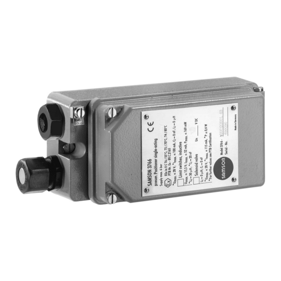
- Page 1 Pneumatic Positioner Type 3766 Fig. 1 · Type 3766 Pneumatic Positioner Mounting and Operating Instructions EB 8355-1 EN Edition November 2011...
- Page 2 Safety instructions Safety instructions The positioner is to be mounted, started up or operated only by trained and experienced personnel familiar with the product. According to these Mounting and Operating Instructions, trained personnel refers to individuals who are able to judge the work they are assigned to and recognize possible dangers due to their specialized training, their knowledge and experience as well as their knowledge of the applicable standards.
-
Page 3: Table Of Contents
Contents Contents Page Design and principle of operation....4 Versions (article code)......6 Technical data . -
Page 4: Design And Principle Of Operation
The pick-up lever (1) and the range spring The positioner is designed either for direct (4) must be selected to match the rated valve attachment to SAMSON Type 3277 Actua- travel and the nominal span of the reference tors or for attachment according to NAMUR variable. - Page 5 Design and principle of operation Travel Supply Pick-up lever 6.1 Span adjuster 1.1 Pin 6.2 Zero adjuster 1.2 Clamp Turnboard 2.1 Nozzle >> Xp restriction 2.2 Nozzle <> Pressure regulator Diaphragm lever 10 Booster Range spring 11 Volume restriction Measuring 12 Solenoid valve diaphragm (optional)
-
Page 6: Versions (Article Code)
4 to 20 mA. Versions (article code) Pneumatic positioner Type 3766- x x x 0 1 x x x x 1 x 0 x 0 Explosion protection Without II 2 G EEx ia IIC T6 acc. to ATEX... - Page 7 Design and principle of operation Pneumatic positioner x x x 0 1 x x x x 1 x 0 x 0 Type 3766- Pneumatic connections ¼-18 NPT ISO 228/1 - G ¼ Electrical connections Without (no additional equipment or solenoid valve) Cable gland M20 x 1.5, blue (plastic)
-
Page 8: Technical Data
Design and principle of operation Technical data Type 3766 Positioner Travel range 7.5 to 30 mm Direct attachment to Type 3277 Actuator 7.5 to 120 mm Attachment acc. to IEC 60534-6 (NAMUR) Opening angle 70°, 75° or 90° depending on the cam disk... - Page 9 Design and principle of operation Electromagnetic compatibility Complying with requirements specified in EN 61000-6-2, EN 61000-6-3 and NAMUR Recommendation NE 21 Explosion protection Refer to article code or list of approvals in Data Sheet T 8355 EN Degree of protection IP 54 (special version IP 65) Weight Approx.
-
Page 10: Attachment To Control Valve
The positioner is attached either directly to sociated symbol become visible. SAMSON Type 3277 Actuator or to valves If the required operating direction does not with cast yokes or with rod-type yokes in ac- correspond to the visible symbol, or if you cordance with IEC 60534-6-1 (NAMUR). - Page 11 Attachment to control valve Actuator stem extends Internal signal pressure Op. direction >> connection Op. direction <> Attachment left Attachment right Connection block Tip of gasket (16) Actuator stem retracts Signal pressure connection over piping Op. direction <> Attachment left Operating direction >>...
- Page 12 Attachment to control valve 2. Screw the associated lever D1 or D2 (for screw. 700 cm² actuator) to the pick-up lever of Actuators with "Actuator stem retracts" the positioner. require the ready-made signal pressure 3. Fasten the distance plate (15) with the line to be installed.
- Page 13 Attachment to control valve For version "Actuator stem retracts" and NOTICE Type 3277-5 Actuators with an effective di- When the valve is installed, the side cover of aphragm area of 120 cm², an internal bore the actuator must be mounted such that the hole ensures that the spring chamber is filled vent plug points downward.
- Page 14 Attachment to control valve Table 1 Mounting kit Required lever with associated clamp and distance plate Actuator size [cm²] Order no. D1 with vent plug for output (38) G ¼ 1400-6790 Connecting thread ¼ NPT 1400-6791 D1 (33 mm long with 17-mm-high clamp) 240 and 350 1400-6370 D2 (44 mm long with 13-mm-high clamp)
-
Page 15: Attachment According To Iec 60534-6
Attachment to control valve Attachment according to IEC 60534-6 Note: Required mounting parts are listed in Table 5. The rated travel of the valve deter- mines which lever and range spring (Table 6) are required. An adapter housing (Fig. 7) is required for Spring Plug screw NAMUR attachment. -
Page 16: Mounting Sequence
Attachment to control valve 2.2.1 Mounting sequence clip must be attached to the lever (18) with the open side pointing downward. Choose the required mounting parts and 6. Plug the lever (18) together with the range spring from Table 4 or 5 and install clamping plate (22) on the shaft (25). - Page 17 Attachment to control valve Mounting position Attachment to NAMUR rib 24 25 21 20 18 Lever N1, N2 Attachment to 19 Pin rod-type yoke 20 Plate 21 Clip 22 Clamping plate 23 Screw 24 Pointer 25 Shaft 26 Lever of the positioner 27a Pin 27b Lock nut 28 Bracket...
- Page 18 Attachment to control valve Table 5 Control valve Travel [mm] With lever Order no. NAMUR mounting kit Valve with cast yoke 7.5 to 60 N1 (125 mm) 1400-6787 22.5 to 120 N2 (212 mm) 1400-6789 Refer to Fig. 7 concerning parts Valve with 20 to 25 1400-6436...
-
Page 19: Attachment To Rotary Actuators
Table 7 are used. Table 7 · Complete mounting parts, including range spring 2, but excluding the cam disk Order no. Attachment acc. to VDI/VDE 3845, level 1 1400-8815 SAMSON Type 3278 Actuator 160 cm² 1400-7103 VETEC Type S 320 cm²... -
Page 20: Mounting The Cam Follower Lever
Align the intermediate piece to ensure When attaching the positioner to the that the air connections of the positioner SAMSON Type 3278 Rotary Actuator point towards the diaphragm housing. (Fig. 8, left), the actuator's inside and the 3. Align the cam disk (40) and scale (39) unused reverse side of the diaphragm are as described in section 2.3.3 and fasten... - Page 21 Attachment to control valve Attachment to SAMSON Type 3278 Attachment acc. to VDI/VDE 3845 Vent plug or filter check valve 33 Positioner 34 Intermediate piece 35 Lever with cam follower roll 36 Adapter 37 Feedback lever 38 Screws 39 Scale...
-
Page 22: Default Setting Of The Cam Disk
Attachment to control valve point towards the cam follower roll. When 2.3.3 Default setting of the cam the starting point is located on the back of disk the cam disk, turn over the cam disk. The valve model used determines the default setting of the cam disk. - Page 23 Attachment to control valve Single-acting spring-loaded rotary actuator Linear cam disk (equal percentage cam disk is represented by a broken and dotted line) Valve opens counterclockwise For valves that open clockwise, the cam disk must be turned over so that the cam follower roll moves over the same disk segments as shown in the figures below, but with the cam disk turning clockwise.
- Page 24 Attachment to control valve Double-acting springless rotary actuator with reversing amplifier Linear cam disk (equal percentage cam disk is represented by a broken and dotted line) View from the positioner onto the actuator shaft Valve opens counterclockwise – Starting position: valve CLOSED Direct operating direction >>...
- Page 25 Attachment to control valve Securing the aligned cam disk To additionally prevent the cam disk from being turned, drill a hole into the adapter (36) or the coupling (44) and install a 2 mm dowel pin. Four bore holes are located centrically around the center hole on the cam disk.
-
Page 26: Reversing Amplifier For Double-Acting Actuators
Refer to the Mounting and Operating In- positioner and screw tight using both the structions EB 8392 EN for the mounting of special screws (1.1). the SAMSON Type 3710 Reversing Ampli- fier. Signal pressure connections : Connect output A to the signal pressure... - Page 27 Attachment to control valve Output 38 Supply 9 From the positioner Control signals to the actuator Reversing amplifier 1.1 Special screws 1.2 Gasket 1.3 Special nuts 1.4 Rubber seal 1.5 Sealing plug 1.3 1.2 Fig. 11 · Mounting a reversing amplifier EB 8355-1 EN...
-
Page 28: Connections
Connections found on the intermediate piece or the re- Connections versing amplifier. Pneumatic connections Note: When using older models with index The pneumatic connections are designed as 3766-x...x. 02 or lower, mounting parts will tapped holes with ¼ NPT or G ¼ thread. have to be replaced as well. -
Page 29: Electrical Connections
Connections Actuator stem retracts (FE): Electrical connections Fail-safe position "Valve OPEN" (for globe and angle valves) DANGER! Risk of electric shock and/or the The required supply pressure for a formation of an explosive atmo- tight-closing valve is roughly estimated from sphere! the maximum signal pressure pst ²... - Page 30 Connections The position transmitter is operated on a nection, an additional cable gland can be two-wire circuit. The usual supply voltage is installed. 24 V DC. Considering the resistance of the Seal cable entries left unused with plugs. supply leads, the voltage at the position Devices used at ambient temperatures be- transmitter terminals can be between 12 and low –20 °C must be fitted with metal cable...
-
Page 31: Switching Amplifier
Connections Accessories Cable gland M20 x 1.5 Black plastic Order no. 1400-6985 Blue plastic Order no. 1400-6986 Nickel-plated brass Order no. 1890-4875 Adapter M20 x 1.5 to NPT: Aluminum, powder-coated 0310-2149 3.2.1 Switching amplifier For operation of the limit switches, switching amplifiers must be connected in the output circuit. -
Page 32: Operation
Operation The starting point (zero) is adjusted at the Operation zero adjuster screw (6.2); the span, i.e. the upper range value, is adjusted at the span Setting the positioner at the adjuster screw (6.1). valve When adjusting, connect a suitable pressure adjuster to the signal input and apply supply Starting point and reference variable pressure to the supply air input. -
Page 33: Adjusting The Proportional Band Xp And Air Delivery Q
Operation 4.1.1 Adjusting the proportional 4.1.2 Settings for actuator: band Xp and air delivery Q "Actuator stem extends" 1. Close the volume restriction Q (11) as NOTICE far as the required positioning speed To ensure that the valve can be closed with permits. -
Page 34: Settings For Actuator: "Actuator Stem Retracts
Operation If the upper range value is incorrect, turn the Starting point (e.g. 1 bar) span adjuster (travel). Four turns correspond 1. Use the pressure adjuster to set the input to a travel change of 10 % in standard oper- signal to 1 bar. -
Page 35: Changing The Operating Direction
Operation Changing the operating If no pressure gauge is available, set the starting point to 0.97 bar instead. direction If you want to change the operating direc- NOTICE tion of directly attached positioners (Fig. 3) After attaching and calibrating the after they have been installed, turn the positioner, make sure that the vent plug on turnboard (7) and change the position of the... -
Page 36: Adjusting The Limit Switches
Operation The terminals 41/42 and 51/52 can op- Adjusting the limit switches tionally be assigned to the switches A and B The positioner version with inductive limit by turning the associated nameplate on the switches has two adjustable tags mounted terminal block (also see Fig. - Page 37 Operation Setting the switching point Move the valve to the switching position and adjust the tag by turning the adjustment screw (53) so that the switching point is reached and indicated by the LED on the switching amplifier. To ensure safe switching under any condi- tion, the switching point is to be adjusted to stop approx.
-
Page 38: Adjusting The Position Transmitter
Operation Adjusting the position Zero point (ZERO) transmitter Use the switches 1 and 2 to preset the zero point and the ZERO potentiometer for fine-tuning. The adjusted value always refers Note: The starting point (zero) and upper to 4 mA. range value (span) must be set before cali- brating the position transmitter. - Page 39 Operation Adjusting the zero point tion procedure at both potentiometers until both values are correct. 1. Use the input signal of the positioner to move the valve to closed position (valve Note on adjusting the position transmitter CLOSED – travel 0 %). for positioners with NAMUR adapter hous- 2.
-
Page 40: Converting The Positioner
Converting the positioner Converting the positioner ter must be located on the right above the inner of the two bore holes (supply). The pneumatic positioner (3766-x...x.04 and higher) can be converted to form a Type 3767 Electropneumatic Positioner. Note: Conversion of explosion-protected versions only on request. - Page 41 Converting the positioner Note: For details on Type 3767 Positioners, refer to Mounting and Operating Instruc- tions EB 8355-2 EN. EB 8355-1 EN...
-
Page 42: Service
Service components relevant for explosion protec- Service tion. Servicing explosion-protected The maximum values for intrinsically safe devices circuits specified in the approvals must be kept. If a part of the device on which the explo- sion protection is based needs to be ser- viced, the device must not be put back into operation until a qualified inspector has as- sessed it according to explosion protection... -
Page 43: Dimensions In Mm
Dimensions in mm Dimensions in mm Pneumatic connections G ¼ or ¼ NPT M20 x 1.5 19.5 Output (38) Input signal Supply (9) Reversing amplifier (optional) Ø110 Attachment IEC 60534-6 Attachment with intermediate (NAMUR) with adapter housing piece for rotary actuators Pneum. -
Page 44: Test Certificates
EB 8355-1 EN... - Page 45 EB 8355-1 EN...
- Page 46 EB 8355-1 EN...
- Page 47 EB 8355-1 EN...
- Page 48 EB 8355-1 EN...
- Page 49 EB 8355-1 EN...
- Page 50 EB 8355-1 EN...
- Page 51 EB 8355-1 EN...
- Page 52 EB 8355-1 EN...
- Page 53 EB 8355-1 EN...
- Page 54 EB 8355-1 EN...
- Page 55 EB 8355-1 EN...
- Page 56 SAMSON AG · MESS- UND REGELTECHNIK Weismüllerstraße 3 · 60314 Frankfurt am Main · Germany Phone: +49 69 4009-0 · Fax: +49 69 4009-1507 EB 8355-1 EN Internet: http://www.samson.de...
Need help?
Do you have a question about the Type 3766 and is the answer not in the manual?
Questions and answers