
Related Manuals for Samson 3761


Summary of Contents for Samson 3761
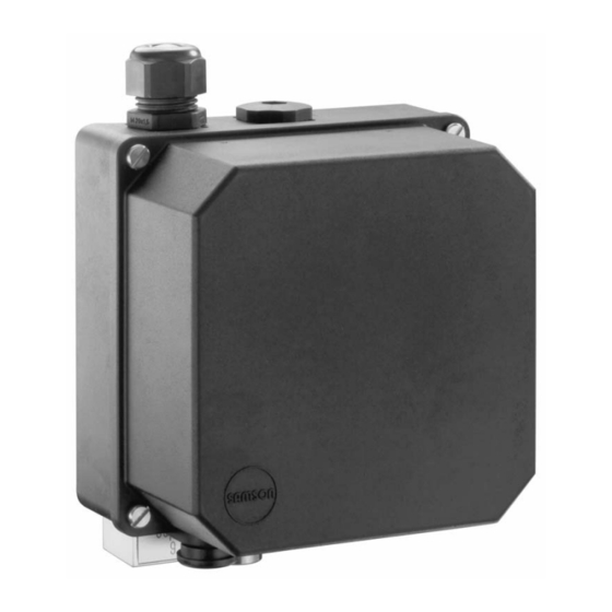
- Page 1 Type 3761 Pneumatic or Electropneumatic Positioner for Rotary Actuators Fig. 1 · Type 3761 Positioner Mounting and Operating Instructions EB 8386 EN Edition July 2007...
-
Page 2: Table Of Contents
Test certificates ......23 Note! Devices with a CE marking fulfil the requirements of the Directives 94/9/EC and 89/336/EEC. The declaration of conformity can be viewed and downloaded on the Internet at http://www.samson.de. EB 8386 EN... - Page 3 If inadmissible motions or forces are produced in the pneumatic actuator as a result of the supply pressure level, it must be restricted using a suitable supply pressure reducing station. Proper shipping and storage are assumed. Positioner versions Type 3761– Explosion protection Without EEx ia IIC T6 Design...
-
Page 4: Design And Principle Of Operation
Any change of the valve position (controlled below or exceeds a given value. variable) is transmitted as a rotary motion of For Type 3761-x21x, the deactivation func- the actuator over the cam disc (2), the tion is initiated when the switching point of pick-up lever (1) and the tension spring (4) 4.08 mA is not reached. - Page 5 Design and principle of operation Fitting position marked p st2 Output 238 Position 2 Output 238 Input p st1 Output 138 Position 1 Output 138 Supply Pick-up lever Double plug Cam disc Amplifier Zero point adjuster Fastening screw Tension spring 10 i/p converter Diaphragm lever (in electropneumatic version)
-
Page 6: Technical Data
Design and principle of operation 1.1 Technical data Type 3761 Positioner Angle of rotation 55° / 70° / 75° / 90° Reference variable Electric 4 to 20 mA (min. 3.6 mA), must be operated on current source Load: 300 Ω at 20 mA (350 Ω at 20 mA with tight-closing... -
Page 7: Attachment To Rotary Actuators
4. Firmly fasten coupling wheel and fol- For SAMSON Type 3278 Rotary Actuators, lower plate to the actuator shaft using mount the spacer delivered with the actuator the pan head screw (6) and disc to the free shaft end of the rotary actuator. - Page 8 Attachment to rotary actuators 5. Place coupling lever (3) including hose 7. Screw the mounting bracket (2) to the clamp and clamping screw (3.1) loosely actuator using four screws (7.1). onto the coupling wheel (4) so that its 8. Fix scale plate (4.1) to the coupling wheel contact stud slides into the oblong so that the arrow tip indicates closed po- hole (3.2).
-
Page 9: Determining The Operating Direction
Attachment to rotary actuators 2.1 Determining the operating di- Double-acting positioners: rection The operating direction is determined by the assignment of the signal pressure out- Important! puts 138 and 238 to the two connections (y1 and y2) of the rotary actuator. The positioner with either single-acting or double-acting output is fixed and cannot be changed by subsequently adding or remov-... -
Page 10: Selecting And Aligning The Cam Disc
Attachment to rotary actuators For example, SAMSON's Type 3278 Actua- 2.2 Selecting and aligning the tor can be mounted on a butterfly valve with cam disc the shaft attached to either the left or the right actuator flange. The positioner is delivered with a 90° linear Fig. - Page 11 Attachment to rotary actuators Single-acting actuator with spring return mechanism Valve opens counterclockwise, linear cam disc (standard) Fail-safe position "valve CLOSED" without supply pressure Orientation of cam disc when control valve is closed Connection: Output 138 Reverse operating direction Connection: Output 238 Direct operating direction Ref.
- Page 12 Attachment to rotary actuators Double-acting actuator with spring return mechanism Linear cam disc (standard) Orientation of cam disc when control valve is closed, additionally apply max. signal press. to actuator Control valve opens counterclockwise (increasing pressure to y1, decreasing pressure to y2) Direct operating direction Reverse operating direction Ref.
-
Page 13: Connections
Connections Aligning the cam disc: Connections Important! 3.1 Pneumatic connections Close the control valve before aligning the cam disc as illustrated in Figs. 5 and 6. Depending on the cover plate, the pneu- For actuators with fail-safe action "valve matic connections are either ¼-18 NPT or OPEN"... -
Page 14: Pressure Gauges
Connections 3.1.1 Pressure gauges 3.2 Electrical connections To control the supply air (Supply) and signal Electropneumatic positioner pressure (Output), pressure gauges as well Connect the wires for the reference variable as a gauge mounting block are required. to terminals +11 and –12 using the hous- Replace the included connecting plate with ing's cable glands. - Page 15 Connections Accessories Order no. Note on selecting cables and wires M20x1.5 cable gland To run several intrinsically safe circuits in Black 1400-6985 one multi-core cable, observe section 12 of Blue 1400-6986 EN 60079-14 and VDE 0165, Part 1. Metal cable gland 1890-4875 Note especially that, for commonly used in- for temperatures below –20 °C...
-
Page 16: Operation - Adjustment
Operation – Adjustment Operation – Adjustment Note! Electropneumatic positioners with tight-clos- 4.1 Starting point and reference ing function are equipped with a slide variable switch on the printed input circuit board to activate or deactivate the function. Note! Important! The positioner is delivered with the default Switch off the activation/deactivation func- settings adjusted by the manufacturer. -
Page 17: Adjustment
Operation – Adjustment Connection Example: With direct operating direction, the control For electropneumatic positioners, con- valve is expected to travel through an angle nect an ammeter to terminals +11 of rotation of 90° (90° cam disc must be in- and –12. stalled) with a reference variable of 4 to For pneumatic positioners, connect con- 20 mA (0.2 to 1 bar). -
Page 18: Spring-Return Actuator: Valve Open Without Supply Air
Operation – Adjustment 4.2.2 Spring-return actuator: valve Note on adjustment with reverse operating OPEN without supply air direction With reverse operating direction (Fig. 5, Note! bottom right), set the starting point (valve For this fail-safe action, a signal pressure CLOSED) to 4.5 mA (0.225 bar). The upper that is high enough to tightly close the valve range value (valve OPEN) will then be regardless of the plant's upstream pressure... - Page 19 Operation – Adjustment Note on adjustment with reverse operating direction With reverse operating direction (Fig. 6, right), set the starting point (valve CLOSED) to 19.5 mA (0.975 bar). The upper range value (valve OPEN) will then be 4 mA (0.2 bar). Important! After adjusting the positioner, close it by re- mounting the cover.
-
Page 20: Adjusting The Limit Switch
Adjusting the limit switch Adjusting the limit switch Adjusting the switching point: Adjust the starting point and upper range Versions equipped with a limit switch can is- value before adjusting the limit switch. sue signals to indicate the travel end posi- 1. -
Page 21: Servicing Explosion-Protected Devices
Servicing explosion-protected devices Servicing explosion-protected devices If a part of the positioner on which the ex- plosion protection is based needs to be ser- viced, the positioner must not be put back into operation until an expert has inspected it according to explosion protection require- ments, has issued a certificate stating this or given the device a mark of conformity. -
Page 22: Dimensions In Mm
Dimensions in mm Dimensions in mm M20x1.5 Supply Input Output 2 Output 1 Connecting dimensions according G ¼ or ¼ NPT pneumatic connections to VDI/VDE 3845, level 1 M20x1.5 EB 8386 EN... -
Page 23: Test Certificates
EB 8386 EN... - Page 24 EB 8386 EN...
- Page 25 EB 8386 EN...
- Page 26 EB 8386 EN...
- Page 27 EB 8386 EN...
- Page 28 SAMSON AG · MESS- UND REGELTECHNIK Weismüllerstraße 3 · 60314 Frankfurt am Main · Germany Phone: +49 69 4009-0 · Fax: +49 69 4009-1507 EB 8386 EN Internet: http://www.samson.de...
Need help?
Do you have a question about the 3761 and is the answer not in the manual?
Questions and answers