Table of Contents
Advertisement
Quick Links
Instruction Sheet
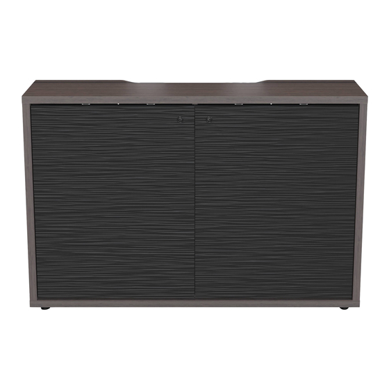
C3 SERIES
Slim Line Credenza
NOTE: C3 1-bay, 2-bay, and 4-bay
models are available in
24" (610 mm, shown) and
32" (813 mm) heights.
THANK YOU
Thank you for purchasing the C3 Series slim line credenza. Please read these instructions
thoroughly before installing or assembling this product.
I-00874
Rev D
Advertisement
Table of Contents

Subscribe to Our Youtube Channel
Related Manuals for Middle Atlantic Products C3 Slim Line Credenza Series


Summary of Contents for Middle Atlantic Products C3 Slim Line Credenza Series
- Page 1 Instruction Sheet C3 SERIES Slim Line Credenza NOTE: C3 1-bay, 2-bay, and 4-bay models are available in 24” (610 mm, shown) and 32” (813 mm) heights. THANK YOU Thank you for purchasing the C3 Series slim line credenza. Please read these instructions thoroughly before installing or assembling this product.
-
Page 2: Table Of Contents
TABLE OF CONTENTS Important Safety Instructions.......................3 - 4 Weight Ratings............................5 Supplied Components and Hardware....................5 - 8 Required Tools............................8 Introduction...............................9 Determining Frame Hanging Height on Wall..................9 - 10 Securing the Frame to a Wall With Steel Studs or Cinderblocks.............11 - 13 Securing the Frame to a Wall With Wood Studs................13 - 14 Securing the Frame to a Solid Concrete Wall..................14 Installing the Power Strip Inside the Frame For Rack Options...............15... -
Page 3: Important Safety Instructions
IMPORTANT SAFETY INSTRUCTIONS • Read these instructions. • Heed all warnings. • Clean only with dry cloth. • Keep these instructions. • Follow all instructions. • Only use attachments/accessories specified by the manufacturer. DANGER HAZARDOUS VOLTAGE: The lightning flash with the arrowhead symbol, within an equilateral triangle is intended to alert the user to the presence of uninsulated dangerous voltage within the product’s enclosure that may be of sufficient magnitude to constitute a risk of electric shock to persons. - Page 4 INSTRUCTIONS IMPORTANTES SUR LA SÉCURITÉ • Lire ces instructions. • Respectez tous les avertissements. • Nettoyer uniquement avec un chiffon sec. • Conservez ces instructions. • Suivez toutes les instructions. • N'utilisez que des accessoires spécifiés par le fabricant. DANGER TENSION DANGEREUSE: Le symbole de la pointe de flèche, dans un triangle équilatéral, est destiné à alerter l'utilisateur sur la présence de tension dangereuse non isolée dans l'enceinte du produit qui peut être d'une ampleur suffisante pour constituer un risque d'électrocu- tion.
-
Page 5: Weight Ratings
WEIGHT RATINGS Model Number Weight Rating C3 1-Bay 24” (610 mm) and 32” (813 mm) Depths 75 lbs. (34 kg) Per Bay, 25 lbs. (11 kg) On Top, 100 lbs. (45 kg) Maximum Total Rated Load C3 2-Bay 24” (610 mm) and 32” (813 mm) Depths 75 lbs. - Page 6 SUPPLIED COMPONENTS AND HARDWARE (CONTINUED) SLIDE-OUT RACK OPTION (C3-TECHKIT4-SO, QUANTITIES PER UNIT) NOTE: This C3-TECHKIT4-SO comes with a C3-FANKIT. (Fankit hardware shown on page 8.) (2x) Lever Lock Securing Rivet Lever Lock Brackets (20x) (5x) 8-32 x 5/16” Lever Lock Plate Washer Thread Forming Screw Partially Pre-Assembled Slide-Out Rack...
- Page 7 SUPPLIED COMPONENTS AND HARDWARE (CONTINUED) FIXED RACK OPTION (C3-TECHKIT4-ST) NOTE: This C3-TECHKIT4-ST comes with a C3-FANKIT. (Fankit hardware shown on page 8.) (2x) Lever Lock Securing Rivet Lever Lock Brackets (20x) Fixed Rackrail Brackets (5x) 8-32 x 5/16” Lever Lock Plate Washer Thread Forming Screw 4”...
-
Page 8: Required Tools
SUPPLIED COMPONENTS AND HARDWARE (CONTINUED) FAN OPTION (C3-FANKIT) (3x) (5x) #6 x 3/8” Fan #10 x 5/8” Fan Controller Mounting Mounting Screw Fan Controller Screw (12x) Wire Tie Global Fan Controller Power Supply (With US, AU, BS, and SAA Attachments) MAGNETIC KEY DOOR LOCK OPTION (MAG-CAB-LATCHKEY) (4x) #8 x ½”... -
Page 9: Introduction
INTRODUCTION After initial unpacking and inspection of your woodkit (A), leave the kit inside the box for added wood surface protection until required for specific assembly steps starting on page 25. DETERMINING FRAME HANGING HEIGHT ON WALL NOTE: Your credenza’s bottom clearance (beneath the lower edge of the woodkit) must be at least 1” (25 mm) for proper air intake. - Page 10 DETERMINING FRAME HANGING HEIGHT ON WALL (CONTINUED) NOTE: • Consider the ADA requirements of a 34” (865 mm) maximum height when determining the overall height of your credenza. (FIGURE B) For more information, refer to the ADA Standards for Accessible Design at: https://www.ada.gov/2010ADAstandards_index.htm •...
-
Page 11: Securing The Frame To A Wall With Steel Studs Or Cinderblocks
SECURING THE FRAME TO A WALL WITH STEEL STUDS OR CINDERBLOCKS 1. Use power driver and ½” drill bit to drill the hole for your top keyhole slot marking into the wall stud (where applicable). NOTE: If securing to cinderblocks, avoid drilling into webs and sides FIGURE D as shown. - Page 12 SECURING THE FRAME TO A WALL WITH STEEL STUDS OR CINDERBLOCKS (CONTINUED) 9. With the frame still in position, use a pencil to mark the remaining keyhole slot locations, in line with the nearest wall studs (where applicable), based on 1-, 2-, or 4-bay models, as shown. (FIGURE H) NOTE: •...
-
Page 13: Securing The Frame To A Wall With Wood Studs
SECURING THE FRAME TO A WALL WITH STEEL STUDS OR CINDERBLOCKS (CONTINUED) 15. Use a power driver and Phillips bit to partially screw remaining ¼”-20 x 2½” bolts (D) and ¼” washers (E) approximately 3/4 of the way through the keyhole slots on the frame and into the anchors. 16. -
Page 14: Securing The Frame To A Solid Concrete Wall
SECURING THE FRAME TO A WALL WITH WOOD STUDS (CONTINUED) WARNING: Total keyhole slot locations specified in these instructions are the minimum anchor points required when securing the frame to the wall. AVERTISSEMENT: Les emplacements de serrure totaux spécifiés dans ces instructions sont les points d'ancrage minimum requis lors de la fixation du cadre au mur. -
Page 15: Installing The Power Strip Inside The Frame For Rack Options
INSTALLING THE POWER STRIP INSIDE THE FRAME FOR RACK OPTIONS NOTE: • The power strip (U or AL), is installed using (2x) power mounting clips (T or AK), and (2x) 10-32 x 1/4” flat head screws (S or AJ) as part of both the Slide-Out Rack (C3-TECHKIT4-SO) and Fixed Rack (C3-TECHKIT4-ST) options. -
Page 16: Installing The Slide-Out Rack Option (C3-Techkit4-So)
INSTALLING THE SLIDE-OUT RACK OPTION (C3-TECHKIT4-SO) TIP: After installing the slide-out rack option, you can remove the rack from the sliders, dress your rack on a close bench or table, and then re-attach your rack onto the sliders. Remove the slide-out rack from the sliders using the first step in “Installing Lever Lock™... -
Page 17: Installing Lever Lock™ Brackets Outside Of Rack Options
INSTALLING LEVER LOCK™ BRACKETS OUTSIDE OF RACK OPTIONS NOTE: • Lever Lock™ brackets are installed outside of both the Slide-Out Rack (C3-TECHKIT4-SO) and Fixed Rack (C3-TECHKIT4-ST) options. This topic shows the Slide-Out Rack, but the procedure is the same for the Fixed Rack. •... -
Page 18: Installing Lever Lock Plates Outside Of Rack Options
INSTALLING LEVER LOCK PLATES OUTSIDE OF RACK OPTIONS NOTE: 4” Lever Lock plate (R or AH) are provided for both the Slide-Out Rack (C3-TECHKIT4-SO) and Fixed Rack (C3-TECHKIT4-ST) options. • Attach the 4” Lever Lock plate (R or AH) by installing the side without the clip into the brackets first. Then, install the side with the clip until it clicks into place. - Page 19 INSTALLING LEVER LOCK OPTION INSIDE SLIDE-OUT RACK (CONTINUED) 2. Choose from the following positions to install your Lever Lock adapter bracket (V) into the slide-out rack (K). (FIGURE U) NOTE: Rack isolated and handle FIGURE U removed for clarity. 3. Insert the tab on the end of the Lever Lock adapter bracket (V) into the opening of your selected position.
- Page 20 INSTALLING LEVER LOCK OPTION INSIDE SLIDE-OUT RACK (CONTINUED) NOTE: Verify the torque on your power driver is on the lightest setting and only increase as necessary. 4. Use a power driver and a 10-32 x ¾” truss screw with washer (W) to secure the Lever Lock adapter bracket to the rackrail.
- Page 21 INSTALLING LEVER LOCK OPTION INSIDE SLIDE-OUT RACK (CONTINUED) 6. Attach the 2” and/or 10” Lever Lock plate (X and Y, respectively) by installing the side without the clip into the brackets first. Then, install the side with the clip until it clicks into place. (FIGURE Y) Clip Side with Side without...
-
Page 22: Installing The Fixed Rack Option (C3-Techkit4-St)
INSTALLING THE FIXED RACK OPTION (C3-TECHKIT4-ST) 1. Install the power strip inside of the frame as explained in “Installing the Power Strip Inside the Frame for Rack Options” on page 15. 2. If desired, use a 7/16” wrench to re-position the rackrails on the fixed rackrail brackets (AC) prior to installing them onto the frame. -
Page 23: Installing The Shelf Kit Option (C3-Shelfkit)
INSTALLING THE FIXED RACK OPTION (C3-TECHKIT4-ST, CONTINUED) NOTE: Verify the torque on your power driver is on the lightest setting and only increase as necessary. 5. Use a power driver, #2 Phillips bit, and (2x) 8-32 x 5/16” thread forming screws (AF) to secure the fixed rackrail brackets to the frame as shown. - Page 24 INSTALLING THE SHELF KIT OPTION (C3-SHELFKIT, CONTINUED) NOTE: Verify the torque on your power driver is on the lightest setting and only increase as necessary. 3. Use a power driver, #2 Phillips bit, and (2x) 8-32 x 5/16” thread forming screws (AN) to secure the wood shelf brackets to the frame as shown.
-
Page 25: Removing Pre-Installed Door(S) From The Woodkit
REMOVING PRE-INSTALLED DOOR(S) FROM THE WOODKIT NOTE: • For ease of woodkit (A) installation, we recommend removing the doors first as shown in this procedure. • When removing doors from a 4-bay model, keep track of which bay each door came from for easy reinstallation as the inner doors differ from the outer doors. -
Page 26: Installing The Grommets (Optional)
INSTALLING THE GROMMETS (OPTIONAL) 1. Determine the desired locations for your grommets (G) on the woodkit (A). (FIGURE AH) NOTE: While you may install the grommets in any location where you would like cables to exit the woodkit (A), pilot holes are located on the bottom inside to easily align with the existing holes in the frame (B), if desired. -
Page 27: Installing The Fan Option (C3-Fankit) To The Woodkit
INSTALLING THE GROMMETS (OPTIONAL, CONTINUED) 4. Separate the tops from the grommets (G) and place the grommets into the holes as shown. (FIGURE AL) Grommet FIGURE AL FIGURE AM 5. Save the grommet tops to install as shown, if desired, after completing the rest of the topics in this instruction sheet and running any cabling through the grommets as needed. - Page 28 INSTALLING THE FAN OPTION (C3-FANKIT) TO THE WOODKIT (CONTINUED) 5. Use (2x) #6 x 3/8” fan controller mounting screws (AT) to mount the inline fan controller (AS) at the location of the pre-drilled holes on the inside top of the woodkit (A). (FIGURE AR) Pre-Drilled Holes Inside Top...
- Page 29 INSTALLING THE FAN OPTION (C3-FANKIT) TO THE WOODKIT (CONTINUED) 6. Run the cable from the fan to the inline fan controller (AS). (Inputs 1 and 2 are interchangeable.) (FIGURE AS) Jumper Pins 7. Connect the small end of the global power supply (AU) to input on inline fan controller (AS).
-
Page 30: Attaching The Woodkit To The Frame
ATTACHING THE WOODKIT TO THE FRAME 1. Team lift the woodkit (A, oriented as shown with the fan opening(s) on the bottom) and carefully attach it to the frame (B). (FIGURE AU) NOTE: • Be careful not to pinch any cables while securing the woodkit to the frame. •... - Page 31 ATTACHING THE WOODKIT TO THE FRAME (CONTINUED) 3. Now, use a power driver, #2 Phillips bit, and 10-32 x 3/8” machine screw(s) (H) to secure the bottom of your frame to the bottom of the woodkit as shown. Do not overtighten. (FIGURE AV) NOTE: The 10-32 x 3/8”...
- Page 32 ATTACHING THE WOODKIT TO THE FRAME (CONTINUED) 4. Use a power driver, #2 Phillips bit, and #10 x 5/8” wood screws (J) to continue attaching the top of your frame to the top of the woodkit as shown. (FIGURE AW) NOTE: •...
- Page 33 ATTACHING THE WOODKIT TO THE FRAME (CONTINUED) 5. Now, use a power driver, a Phillips bit, and #10 x 5/8” wood screws (J) to continue attaching the bottom of your frame to the bottom of the woodkit as shown. (FIGURE AX) NOTE: •...
-
Page 34: Reinstalling The Door(S)
REINSTALLING THE DOOR(S) 1. Reinstall the door (or doors on 2- and 4-bay models) to the woodkit by carefully hooking together the front sections of the hinge hardware (top hinge pictured) as shown. (FIGURE AY) Door Woodkit Side Panel NOTE: Hinge, door, and woodkit side panel isolated for clarity. -
Page 35: Adjusting The Door(S)
ADJUSTING THE DOOR(S) • If necessary, use a #2 Phillips screwdriver to adjust door hinges as shown. (FIGURE AAA) Side Adjustment Height Adjustment Depth Adjustment FIGURE AAA USING THE MAGNETIC KEY LATCH OPTION (MAG-CAB-LATCHKEY) 1. Open the door on the bay you wish to install the magnetic key latch option. - Page 36 USING THE MAGNETIC KEY LATCH OPTION (MAG-CAB-LATCHKEY, CONTINUED) 4. Insert plunger (AY) into the hole on the rear of the magnetic door latch (AZ) as shown. (FIGURE AAD). FIGURE AAD 5. Use #2 Phillips screwdriver and (2x) #8 x ½” wood screws (AW) to loosely attach the magnetic door latch (AZ) using the pre-drilled holes on the inside of the door (opposite side of the door hinges) as shown.
-
Page 37: Warranty
Voice: 613-836-2501 - Fax: 613-836-2690 / ca.middleatlantic.com - customerservicecanada@middleatlantic.ca Factory Distribution USA: NJ - CA - IL Canada: ON At Middle Atlantic Products we are always listening. Your comments are welcome. Middle Atlantic Products is an ISO 9001 and ISO 14001 Registered Company. Page 37...
Need help?
Do you have a question about the C3 Slim Line Credenza Series and is the answer not in the manual?
Questions and answers