Table of Contents
Advertisement
Quick Links
Instruction Sheet
ASR SERIES
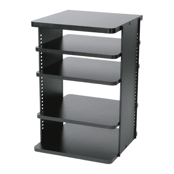
Slide-Out Rotating Shelf System
THANK YOU
Thank you for purchasing the ASR Slide-Out Rotating Shelf System. Please read
these instructions thoroughly before installing / assembling this product.
PRODUCT FEATURES
- Adjustable shelving
- Cable management included
- Easy access to rear connections
I-00140
Rev G
Advertisement
Table of Contents

Related Manuals for Middle Atlantic Products ASR Series


Summary of Contents for Middle Atlantic Products ASR Series
- Page 1 Instruction Sheet ASR SERIES Slide-Out Rotating Shelf System THANK YOU Thank you for purchasing the ASR Slide-Out Rotating Shelf System. Please read these instructions thoroughly before installing / assembling this product. PRODUCT FEATURES - Adjustable shelving - Cable management included...
-
Page 2: Parts List
PARTS LIST Page 2... - Page 3 PARTS LIST (CONTINUED) MODEL NUMBER PART LETTER ASR-30 ASR-36 ASR-42 ASR-48 NAME DESIGNATION QUANTITY PANEL BOTTOM PANEL/SHELF SHELF BASE (2 SLIDES) BASE (4 SLIDES) SIDE LOCKING BRACKET MOUNTING TEMPLATE LOCKING PANEL LACER Page 3...
-
Page 4: Hardware List
HARDWARE LIST 7/8" Dia. Velcro Hook ® (Actual size) ® 15" Velcro loop non-adhesive (Actual size) ® 15" Velcro hook adhesive (Actual size) (Actual size) (Actual size) middleatlantic.com 5/8" Dia. Velcro Loop ® (Actual size) Page 4... - Page 5 HARDWARE LIST CONTINUED PART ASR-30 ASR-36 ASR-42 ASR-48 PART REQUIRED NAME QUANTITY SWIVEL DISC 1" SHOULDER BOLT 1-1/4" WOODSCREW 5/8" WOODSCREW 3/4" MACHINE SCREW 5/8" DIAMETER ® VELCRO LOOP 7/8" DIAMETER ® VELCRO HOOK 15-1/2" ® VELCRO LOOP 15-1/2" ® VELCRO HOOK HEX KEY DRIVER...
- Page 6 TOOLS REQUIRED (User supplied) - Hammer - # 2 Phillips screwdriver - Screwgun or drill: # 2 Phillips bit and low torque setting - 1/8" Drill bit - Clear or masking tape DIMENSIONS Part # Overall Height *Minimum Width Minimum Depth-No Setback Min.
- Page 7 Installation Opening Preparation FIGURE A 1) Install Lacer Bar(s) (K) onto rear wall of host enclosure as shown. (FIGURE A) Your installation may require Lacer Bars to be placed in a different position. Lacer Bar placement should be arranged so that signal wires can be separated from power/speaker cables upon finishing .
-
Page 8: Top View
BASE FIGURE A Line up rollers as shown LOCKING PANEL (D/E) CENTER HOLE ROLLER TOP VIEW UNPACK AND INSTALL SYSTEM BASE / SLIDER ASSEMBLY NOTE: If any parts are damaged or missing, call 1-800-266-7225. Do not return to the place of purchase. 1) Unpack all parts carefully on a flat, clean surface. - Page 9 FIGURE B Template shown in flush mounting position INSTALLATION OPENING TEMPLATE (H) Template shown in setback mounting position Use tape to attach the paper mounting template (H) to the base of the installation opening. (FIGURE B) NOTE: The template is marked with a dotted fold-line to help position for flush or setback mounting.
- Page 10 FIGURE C FIGURE D FRONT LOCKING PANEL (G) FRONT Remove the mounting template and mount the locking bracket (G) to the base of the opening using (2) #12 wood screws (O) supplied (FIGURE C). Place the base assembly in the opening with the flat edge facing the front of the opening and the rounded corners facing the rear.
- Page 11 ASSEMBLY AND INSTALLATION OF SHELVING SYSTEM NOTE: All holes in top & bottom panels are arranged in such a way that it is only possible to assemble them in one fashion. DO NOT DRILL NEW HOLES. FIGURE E Install these screws first FRONT Assemble bottom panel/shelf (B) to steel side panels (F)
- Page 12 FIGURE F FIGURE G Shoulder bolt CENTER HOLE Line up rear edges to insert shoulder bolt FRONT FRONT 2) Carefully lift the assembled shelving system into position on the base/slider assembly. Use the rear edge of the shelving system for location. The rear of the shelving system bottom should be flush with the rear of the system base/slider assembly and flush with the sides of the installation opening (FIGURE F).
- Page 13 EQUIPMENT AND SHELVING INSTALLATION: PROTECTIVE BACKING NOTE: Before proceeding with equipment mounting, remove all media sources from all devices. CD's, DVD's, VHS tapes, etc 1) Remove the locking panel (J) from the front of the shelving system (if installed). Extend shelving system and rotate to allow for rear access of equipment to be installed.
- Page 14 NOTE: Before proceeding with equipment and shelf mounting: a minimum of 1/2" should be added to the height of each piece of equipment to allow for heat to dissipate from the top of each unit. However, you may choose to add more than 1/2" to the height of each piece of equipment to result in evenly spaced shelves upon finishing.
- Page 15 This process will help you to place your components in the system beginning at the bottom, evenly spaced, without trial and error. Measure equipment height including feet Height SUGGESTED NOT SUGGESTED (ASR-36 SHOWN) PART # ASR-30 ASR-36 ASR-42 ASR-48 23.125" 28.375"...
- Page 16 * EXAMPLE * Example showing 5 components being installed in an ASR-36 ASR-36 AVAILABLE MOUNTING SPACE 28.375" " ENTER TOTAL COMPONENT HEIGHT dd up the heights of all components. " Record the overall height dimension on Line A, in the appropriate column. Then subtract Line A from AVAILABLE MOUNTING SPACE DIVIDE UNUSED SPACE...
-
Page 17: Cable Management
CABLE MANAGEMENT Double Sided Cable Straps WARNING: To reduce to risk of electrical shock, complete the following steps before supplying power to equipment. 1) Pull out and rotate shelving system in the direction you prefer. HINT: Once cables are connected to equipment installed in the shelving system and laced to Lacer Bar(s), the shelving system will be restricted and should only be turned in the direction chosen. -
Page 18: Warranty
WARRANTY Middle Atlantic Products, Inc. (the "Company") warrants the ASR Series Slide-out Rotating Shelf System to be free from defects in material or workmanship under normal use and conditions for a period of (3) three years from date of shipment by the Company. -
Page 19: Installation Notes
INSTALLATION NOTES Page 19...
Need help?
Do you have a question about the ASR Series and is the answer not in the manual?
Questions and answers